

Page 1
Page 2

Thank you for purchasing the
SuperGuard GPS/ GPRS Car Security
and Tracking device. Please read all
instructions carefully before
operation, to ensure your complete
understanding and to obtain the best
possible performance from the unit.
Warranty
The Yield Technology Co., Ltd. (YTC) warrants to the purchaser that this product, under
normal use and conditions, will be free from defects in materials and workmanship for a
period of 12 months from the date of original purchase. If a product proves defective
during this warranty period, YTC, at its option, either will repair the defective product
without charge for parts and labor, or will provide an exchange for the defective product.
In order to obtain service under this warranty, the purchaser must notify YTC of the defect
before the expiration of the warranty period and make suitable arrangements for the
performance of service. The purchaser shall be responsible for appropriate packaging and
shipping with a carrier designated by YTC, with shipping charges paid by recipient (YTC).
This warranty shall not apply to any defect, failure or damage caused by improper use or
improper or inadequate maintenance and care, alterations, mishandling or accidents. YTC
shall not be obligated to furnish service under this warranty to costs incurred for
installation, to correction of antenna problems, removal or reinstallation or to damage to
video tapes, discs, speakers, accessories or vehicle electrical system.
The extend of YTC’s liability under this warranty is limited to the repair or replacement
provided above and, in no event, shall the company’s liability exceed the purchase price
paid for this product.
THIS WARRANTY IS GIVEN BY YTC IN LIEU OF ANY OTHER WARRANTIES,
EXPRESS OR IMPLIED. YTC AND ITS VENDORS DISCLAIM ANY IMPLIED
WARRANTIES OF MERCHANTABILITY OR FITNESS FOR A PARTICULAR
PURPOSE. YTC’S RESPONSIBILITY TO REPAIR OR REPLACE DEFECTIVE
PRODUCTS IS THE SOLE AND EXCLUSIVE REMEDY PROVIDED TO THE
PURCHASER FOR BREACH OF THIS WARRANTY. YTC AND ITS VENDORS
WILL NOT BE LIABLE FOR ANY INDIRECT, SPECIAL, INCIDENTAL OR
CONSEQUENTIAL DAMAGES IRRESPECTIVE OF WHETHER YTC OR THE
VENDOR HAS ADVANCE NOTICE OF THE POSSIBILITY OF SUCH DAMAGES.
Table of Contents
1. Parts & Accessories page 4
2. SuperGuard Vehicle Unit - Features page 6
3. Preparations page 7
4. Installation page 8
5. Vehicle Unit – LED Indicators page 16
6. Getting Started page 17
7. Activate/ Disable Vehicle Security page 18
8. Car Alarm/ Anti-Theft Features page 21
9. Emergency Alarms page 24
10. Monitoring Activities page 26
11. Locating and Tracking page 28
12. Phone Call Operation page 30
13. Retrieving Device IMEA Number page 30
14. Technical Specifications page 31
Page 3
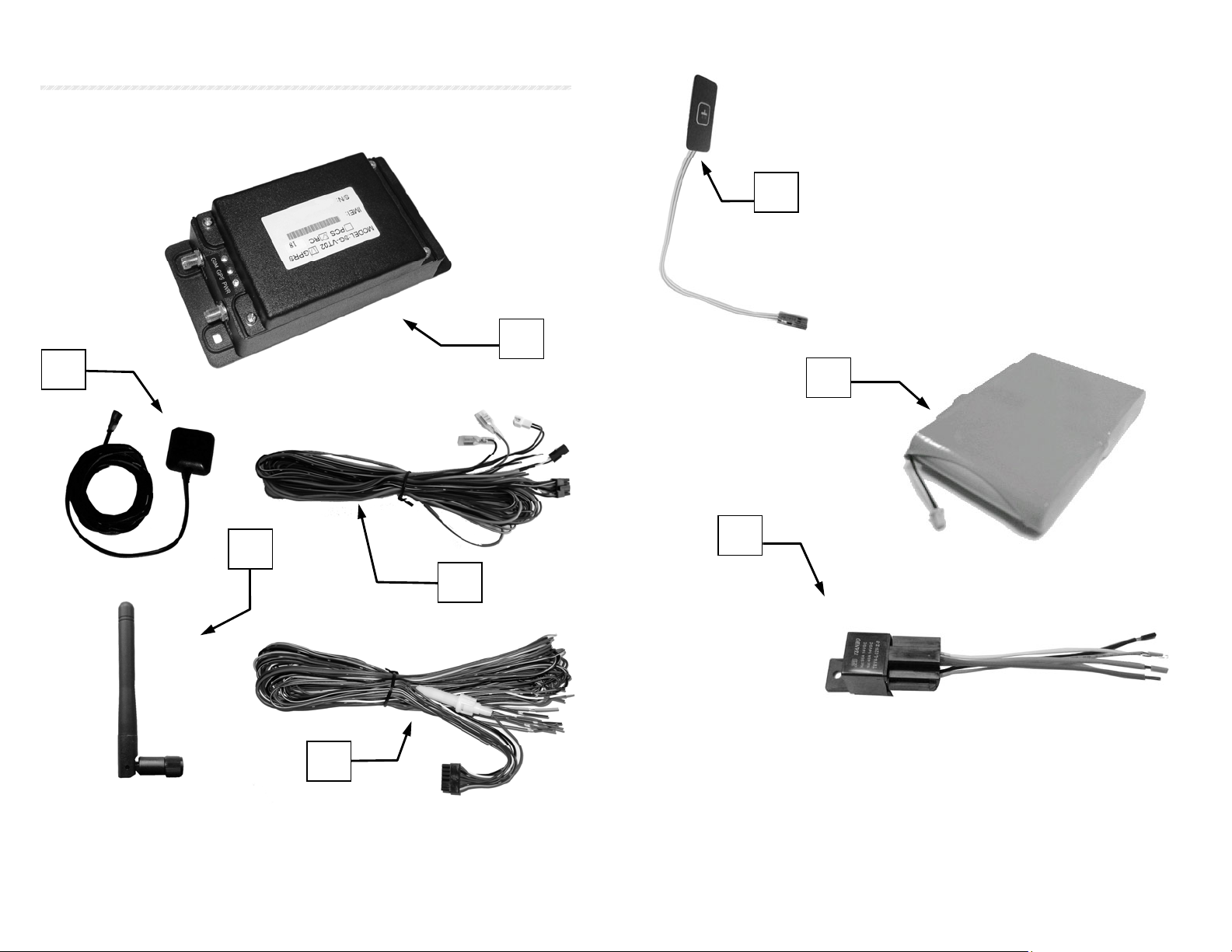
1. Parts & Accessories
On receipt of your SuperGuard system, please check that all contents
are complete and correct.
1
2
3
4
1. SuperGuard GPS/GPRS Main Unit
2. GPS Aerial
3. GSM Antenna
4. 10-PIN Wiring Harness (CON 1)
6
5. 14-PIN Wiring Harness (CON 2)
6. SOS Emergency Button
7. 7.2V Rechargeable Li-Ion Battery pack
8. Engine Immobilizer Relay
7
8
4
5
5
Page 4
2. SuperGuard Vehicle Unit – Features
The SuperGuard SG-VT02 is equipped with a variety of basic anti-theft or
car alarm features.
¾ As an authorized Contact person you can use your GSM phone to
activate or disarm vehicle security features through 2-RING and 4-RING
phone calls or short message commands. Alternately, you will be able to
activate or disarm the Vehicle Unit or query its location and status over
Internet Website or GPRS enabled cell phones
In addition, you can remote control certain security features, like locking
or unlocking the vehicle doors, enabling or disabling engine immobilizer
via short message commands
¾ If car doors have been opened, your vehicle has been moved or the
Vehicle Unit has been cut off from the main power source while the
vehicle security is in armed status, car alarm will sound and send alarm
messages with GPS positions and status reports to all Contact numbers.
You will also be able to track your vehicle on a Website via Internet
Explorer or mobile on GPRS enabled cell phones.
¾ The Vehicle Unit comes with one SOS Push Button designed for
emergency calls, accidents or hijacking. It should be placed at a hidden
place within reach of the driver on the dashboard.
The SOS Button will report emergency calls and accidents immediately
to Control Base and Contact persons. In addition, existing crash sensors
can be applied to automatically report traffic accidents.
¾ You will be enabled to setup and configure monitoring activities and
alerts to the Vehicle Unit, using Control Base software or Tracking Web
services via Internet Explorer or mobile on GPRS enabled cell phones
¾ You can define and load up to 4 restricted areas (Geo-Fence areas) to
your device and setup maximum speed limits.
¾ From your Control Base software or over Internet Websites you are able
to setup tracking schedules and track vehicles in real time.
6
3. Preparations
In order to install the SuperGuard Vehicle Unit properly, the
following preparations should be carried out:
Prepare one operational GSM SIM card. Make sure that the SIM card
• can operate without PIN protection (ask the GSM
operator to do this). Ask the GSM operator for the
SMSC (SMS Service Center) and Data Call (if
applicable) numbers.
• Empty the SMS storage of the SIM card using
operational GSM phone (please refer your GSM phone
manual to do this).
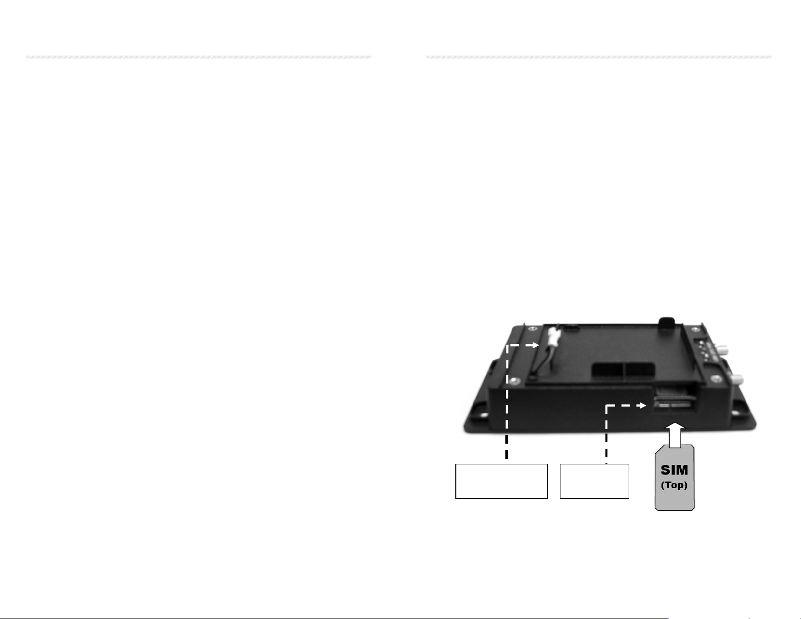
• Unscrew and remove the top cover of your Vehicle Unit. Insert
the SIM card by sliding it into the SIM slot, with the chip
module facing to the bottom side.
• Push the SIM card into the slot until it is engaged.
• To remove the SIM card, push it in again to release.
Spare Battery
Connector
SIM Card
Slot
7
Page 5
4. Installation
The Vehicle Unit will only operate on 12 V systems with negative earth
(Negative to body).
o Before starting installation, disconnect the vehicle battery and
o If you want to install the Vehicle Unit in the passenger
o The GPS antenna should be positioned at a place where it will
o The SOS button should be installed at a place on the dashboard.
o Do not connect the spare battery to the Vehicle Unit before you
8
NOTE: Please note that installation methods may
vary between vehicle models. For expert wiring
and connecting please contact a professional car
electronics workshop for installation support and
maintenance.
observe other manufacturers safety instructions regarding
alarm systems, airbags or anti theft radio coding.
compartment, make sure that all antenna cables and wiring is
protected from sharp edges and is routed in such a manner that
it will not be pinched.
have an unobstructed view of the sky. The ideal location is on
the inside of the windscreen. The aerial will not work if it is
placed beneath metal or metallic glass coatings.
It should be hidden but easily accessed in emergency cases. To
avoid “false alarms” or unintended confusion with other
electronic control buttons, it should be placed separate from
dashboard controls and car audio devices.
have completed all electrical wiring and connections to the
device.
Connecting The Vehicle Unit:
To obtain maximum functionality of your Vehicle Unit you should
locate and connect the following electrical output and input wires from
the vehicle to the complying pigtails of the Vehicle Unit’s CON 1:
The following wiring needs to be applied to CON 2:
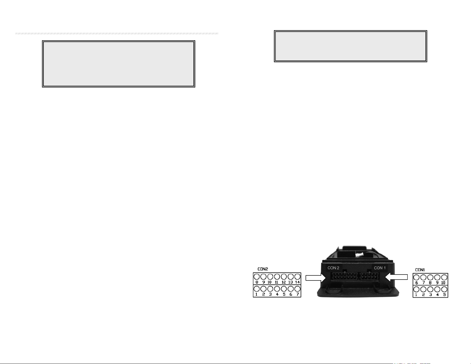
When connecting, refer to the cable description for the Vehicle Unit
connectors CON 1 and CON 2 according to the wiring diagrams on the
following pages.
NOTE: Finish all wiring and connections to the
correct vehicle outputs and inputs before you apply
the connectors to the Vehicle Unit !!!
• 2 cables to Alarm Siren
• 2 cables to 12V Power Supply (+ from Vehicle Battery)
and GND
• 1 cable to SOS Emergency Button (Dry Contact)
• 2 cables from existing Car Alarm (if applicable)
• 1 cable to interior light (door signal output) – Only use
this feature if your automatic dome light switch comes
without delay timer
• 1 cable from ACC Out (+ from ACC+)
• 1 cable to Engine Relay (plus 2 from Ignition)
• Central Lock; Unlock Doors (2 wires: COMM+NO/NC)
• Central Lock; Lock Doors (2 wires: COMM+NO/NC)
9
Page 6

CON 1: Cable Description and Colors
PIN
No.
1 Optional (free) Black/White
2 Optional (free) Red/White
3 Optional (free) Red
4 (free) Black
5 (assigned) Microphone Input (HF+) Purple
6 Connect to Alarm Siren (COMM) Blue/White
7 Connect to Alarm Siren (NO) Blue
8 (assigned)Microphone to Ground (GND) Purple/White
9 (assigned) Headset Speakers (HF+) Green
10 (assigned) Headset Speakers (HF-) Green/White
Cable Description Color
CON 2: Cable Description and Colors
PIN
No.
1 +12V Battery Power Input (+) Red
2 Power Ground (GND) Black
3 Connect to SOS Emergency Button (+) Blue
4 Arm Switch (from existing Car Alarm) Brown
5 Disarm Switch (from existing CarAlarm) Brown/White
6 Connect to Interior Light (if no delay timer) Purple
7 ACC (+12V) Yellow
8 Immobilizer Relay (+) White
9 Door Unlock (NO) Purple/White
10 Door Unlock (COMM) Grey
11 Door Unlock (NC) Black/White
12 Door Lock (NO) Red/White
13 Door Lock (COMM) Green/White
14 Door Lock (NC) Green
10
Cable Description Color
Installation of SOS Emergency Push Button
CON 2/ PIN 3
SOS Push Button
12 V
Installation of Relay for Immobilizer function:
To apply the Engine Enable/ Disable Relay, connect the following
cables from the relay socket:
1. Black: Connect to one end
of Ignition line (A)
2. White: Connect to Vehicle
Unit, CON 1; PIN8 (White)
3. Middle: Connect to engine
end of ignition line (B)
4. Free
5. Yellow: Connect to ACC
Plug the Relay into the Relay Socket to connect.
11
Page 7

CON 1 Wiring Diagram (CON 2 see opposite side)
¾ When laying the wiring loom
• Try to ' bury' all wiring
Avoid abrasive corners and sharp edges
•
Avoid sharp folding and pinching the cables
•
Make sure that the connections have been made correct before you
connect the Main Connector to the Vehicle Unit.
Vehicle Unit Vehicle Wiring PIN
12
Page 8

Finish the Installation
o To ensure that the Vehicle Unit
is able to operate even without
vehicle battery support, you will
need to connect the supplied
spare battery to the device.
o Insert the battery into the
battery compartment and
connect both connectors. Close
the top cover of the device and
fasten it to the unit with the
supplied screws.
o The GPS Aerial shall be installed either top of the dashboard or
close to the rear window of the car, so that it can see the sky. It
will pick up signals through glass and plastic, but will not “see
the sky” through metal or other conductive surfaces. To avoid
distractions of the GPS signal make sure the distance to
metallic objects is at least 10 cm.
14
NOTE: Please note that adhesive sun absorber
screens may consist of metal. This can distract or
block the GPS signal. In that case the GPS aerial
should be mounted outside of the vehicle.
15
Page 9

5. Vehicle Unit – LED Indicators
Z
Y
X Power LED (green)
¾ If LED flashes:
Device is powered on
Y GPS/ GPRS LED (red)
¾ If LED flashes:
Device has GPS lock
¾ If LED stays on for a period of time:
Device is dialing GPRS service. If connected, LED
will flash several times if connection to Control
Base was successful. Will repeat if not successful.
Z GSM LED (green)
¾ If LED flashes:
Device is registered to GSM network, able to send/
receive SMS and place or receive phone calls
¾ If LED stays on constantly:
Device is still registering to GSM network, no SIM
card inserted or network unavailable
¾ If LED is off for a period of time:
¾ Device is communicating with Control Base or Contact
numbers
16
6. Getting Started
After plucking the Main Connector into the Vehicle Unit, the device
will power up and automatically attempt to register to GSM network.
Provided that your vehicle and the Vehicle Unit’s GPS antenna is
X
positioned in an area with clear un-obstructed view of the sky, the
device will then start scanning for GPS satellites to obtain its first GPS
lock. This first fix can take several minutes.
To use the communication and vehicle security features of the device,
some mandatory setup parameters need to be configured from the
Control Base software or Tracking Websites before it is able to
operate properly.
After setting up a user account at the Control Base, enter the following
required SIM card details, SMS and GPRS dial-up information and
Contact numbers, before you send them through SMS initialization
command to the Vehicle Unit:
Submit all these information to complete the setup of your Vehicle
Unit. Once the Vehicle Unit initialization command is received, the
alarm siren will sound twice to indicate that the initialization has been
completed successfully.
IMPORTANT NOTE: Once your device has been
initialized, all following commands sent through
the Control Base have to use the same GSM
number (Control Center Number). To switch to a
different Control Center number at a later time,
you will need to send an Initialization command
with the modified Control Center number using
the original GSM number at the Control Base.
17
Page 10
7. Activate/ Disable Vehicle Security
As an authorized Contact person, you are
able to activate and disable the vehicle
security system either from your GSM cell
phone (Caller ID must be enabled), Control
Base software or through user account from
one of the Tracking Websites.
IMPORTANT NOTE:
Please be aware that all cell phone numbers configured at the Control
Base as “Contact 1, 2 and 3” will be able to get notifications and remote
control security features of your vehicle that are significant for your
vehicle’s security, like:
Receiving SMS alarms and positions in case of unauthorized moving
of vehicle or opening of doors
Receiving SMS notifications in case of car accidents, emergency calls
or low battery warnings
Activate or disable the vehicle security remotely by phone call or SMS
Remote command central door locks, disable/ enable engine
immobilizer
¾ To activate the car alarm from a cell phone, place a 2-RING phone
call (ca. 5 sec.) to the Vehicle Unit number. This will lock the doors,
disable the ignition and activate the vibration sensor in the device.
Dial Call to Vehicle Unit Î 2 Rings ÎHang Up
In addition, you will receive an SMS short message from the device,
confirming that your vehicle is secured now.
¾ To disable the car alarm, place a 4-RING phone call (ca. 10 sec.) to
the Vehicle Unit number. This will enable the engine, and
deactivate the vibration sensor in the device.
Dial Call to Vehicle Unit Î 3 Rings… 4 Rings ÎHang Up
In addition, you will receive an SMS short message from the device,
confirming that your vehicle security is disarmed now
¾ To use SMS command to activate the vehicle security, type and
send this command to the Vehicle Unit to activate the security
system:
$ARM,1 Î Enter Vehicle Unit Number Î Send
¾ To use SMS command to disable the vehicle security, type and send
this command to the Vehicle Unit to activate the security system:
$ARM,0 Î Enter Vehicle Unit Number Î Send
¾ Alternately, you are able to activate or disarm the Vehicle Unit or
query its location and status over Internet Website or GPRS
enabled cell phones. Please refer to the Software or Web User
manuals to do this. Please note that security disable commands
sent from the Website will enable ignition and vibration sensor, but
not automatically unlock the vehicle doors.
¾ If your Vehicle Unit comes with an operational RF remote control,
you can use that remote control to lock and unlock the doors. This
will automatically activate or disable the security system as
described above.
NOTE: Only the Contact Numbers and Control
Base will be able to process remote commands.
Using other cell phones or dial-up software to send
commands to the unit will have no effect on the
Security System.
19
Page 11

Additional Control Commands
p
Car Owners and Contact persons can use their authorized mobile
phone numbers to control the central locking system and lock or
unlock the vehicle doors through short message commands.
¾ To use SMS command to lock the vehicle doors, type and send this
command to the Vehicle Unit:
$DOR,1 Î Enter Vehicle Unit Number Î Send
¾ To use SMS command to unlock the vehicle doors, type and send
this command to the Vehicle Unit:
$DOR,0 Î Enter Vehicle Unit Number Î Send
Car Owners and Contact persons can use their authorized mobile
phone numbers to enable or disable the engine immobilizer via short
message commands:
¾ To use SMS command to lock the vehicle engine and doors, type
and send this command to the Vehicle Unit command:
$ENG,1 Î Enter Vehicle Unit Number Î Send
¾ To use SMS command to unlock the vehicle engine and doors, type
and send this command to the Vehicle Unit:
$ENG,0 Î Enter Vehicle Unit Number Î Send
20
NOTE: To use remote control commands from
authorized Contact numbers, you will need to
enable Caller ID features on your cell phone.
8. Car Alarm/ Anti-Theft Features
As soon as the Security of the SuperGuard
Vehicle Unit has been activated, the following car
security features will come into effect:
Car Doors Open
¾ If the car door has been opened while the Vehicle Unit is in armed
status:
The alarm siren will sound for 30 seconds.
The Vehicle Unit will send an alarm message with updated
GPS positions to the Control Base. The Control Base
software will find the street name and closest intersection
from a map server and send these details through SMS
short messages to a list of up to three authorized Contact
persons, with the text (example):
If present, users can also track their vehicle on a Website
via Internet Explorer or mobile on GPRS enabled cell
phones.
Peter’s truck is in Roosevelt
Blvd., near intersection
Madison; GPS Car Alarm:
Door O
en
21
Page 12

g
Vehicle is Moving
¾ If the car has been moved in armed status (for example, in case of
tow-away), the following car alarm features will come into effect:
The alarm siren will sound for 30 seconds.
The Vehicle Unit will send an alarm message with updated
GPS positions to the Control Base. The Control Base
software will find the street name and closest intersection
from a map server and send these details through SMS
short messages to a list of up to three Contact persons, with
the text (example):
If present, users can also track their vehicle on a Website
via Internet Explorer or mobile on GPRS enabled cell
phones.
Peter’s truck is in Madison
Ave, near intersection
Brixton Rd; GPS Car
Alarm: Vehicle Movin
Vehicle Battery Cut Off
¾ If the Vehicle Unit has been removed or cut from the main power
source or the car battery gets too low, the following car alarm
features will come into effect:
The Vehicle Unit will send an alarm message with GPS
position to the Control Base.
The Control Base software will find the street name and
closest intersection from a map server and send these
details through SMS short messages to a list of up to
three authorized Contact persons, with the text:
22
Peter’s truck is in Gatwick
Parkway., near intersection
Madison; GPS Car Alarm:
Main Power Cut
NOTE: If the vehicle battery has been removed,
you will not be able to remote control door locks.
To disable vehicle security, you still can either use
the supplied Remote Control, place 4-RING call or
send $ARM,0 command manually.
Other Security Alarms
¾ If the vehicle has been equipped with a standard car alarm system
which is connected to the SuperGuard Vehicle Unit, the unit will
report to the Control Base, when the existing car alarm goes off:
The Vehicle Unit will send an alarm message with GPS
position to the Control Base.
The Control Base software will find the street name and
closest intersection from a map server and send these
details through SMS short messages to a list of up to
three authorized Contact persons, and alarm text
according to event.
¾ If the ACC ignition wire inside the vehicle has been short-cut while
the security system is active, and no “Door Open” alarm has been
triggered (for Cabriolets):
The Alarm Siren will sound for 30 seconds.
You will receive an alarm text message.
23
Page 13

9. Emergency Alarms
The SuperGuard security system includes special
safety features that can save your life in case of
accidents, hijacking or emergency cases.
SOS Emergency Call
¾ The SuperGuard security system comes with a self-adhesive SOS
push button that can be installed at a hidden place within reach of
the driver. Pressing this button will start the following actions:
The Vehicle Unit will send an alarm message and GPS
coordinates to the Control Base. The Control Base software
will find the street name and closest intersection from a map
server and send these details through SMS short messages
to all Contact numbers, with the text:
The Vehicle Unit automatically dials a phone call to the
main Contact number (Contact 1).
If applicable, the SOS phone call can be used as “silent call”
to allow users or operators to monitor events and sounds in
the vehicle.
24
Peter’s truck is in Madison
Ave, near intersection
Brixton Rd.; GPS Car
Alarm: SOS !
Users in the car can hang up the automatic SOS phone call
by pressing the SOS button again.
After placing the SOS phone call, the vehicle unit will
automatically start tracking and update GPS positions to
the Control Base every 60 seconds over a period of 30
minutes.
25
Page 14
10. Monitoring Activities
y
Users are able to setup and configure
monitoring activities and alerts to the
Vehicle Unit, using Control Base software or
Tracking Web services via Internet Explorer
or mobile on GPRS enabled cell phones.
Geo-Fence Alarms
¾ If the Vehicle Unit has been configured with a set of restricted
geographic areas (Geo-Fences), the following activities will be
triggered when a Geo-Fence violation occurs:
The Vehicle Unit will send an alarm message and GPS
coordinates to the Control Base. The Control Base software
will find the street name and closest intersection from a map
server and send these details through SMS short messages
to a list of up to three authorized Contact persons, with the
text:
Over Speed Alarms
¾ If the Vehicle Unit has been configured with a maximum speed
limit, the following activities will be triggered when the vehicle
speed exceeds the speed limit:
26
Peter’s truck is in Arlington.,
near intersection Fairfax
Ramp; GPS Car Alarm:
GEO Fence Alert
The Vehicle Unit will send an alarm message and GPS
coordinates to the Control Base. The Control Base software
will find the street name and closest intersection from a map
server and send these details through SMS short messages
to all Contact numbers, with the text:
NOTE: Over Speed Alarms will only be reported if
ignition is on and the Vehicle Unit has been
connected to ACC (CON 2/ PIN 8).
Peter’s truck is in Highway
166, near intersection Gleebe;
GPS Car Alarm: Over Speed
Battery Low Warning
¾ If no main power source is connected and the included battery
pack in the Vehicle Unit runs low on power:
The Vehicle Unit will send an alarm message and GPS
coordinates to the Control Base. The Control Base software
will find the street name and closest intersection from a map
server and send these details through SMS short messages
to all Contact numbers, with the text:
Peter’s truck is in Madison
Ave., near intersection
Brixton Rd.; GPS Car
Alarm: Batter
Low
27
Page 15

11. Locating and Tracking
Authorized users can interrogate the Vehicle Unit
to receive locations, street names and details. If
present, they can poll and track their vehicles
through Control Base software or Tracking Web
services via Internet Explorer or mobile on GPRS
enabled cell phones.
Vehicle Tracking
¾ From the Control Base software, over Internet from the Tracking
Website or GPRS enabled cell phones, you are able to receive
updated GPS locations any time and display them on a map, and
view Tracking history and results over unlimited time.
¾ From the Control Base or Websites, you are also able to setup
Tracking schedules for periods up to 45 days, in intervals between
30 seconds and 17 hours.
¾ You can start and end tracking your vehicle in real-time, following
its route on a map (GPRS connection and network coverage
required).
¾ You can setup storage sequences in which you wish the Tracking
device to store GPS positions to its memory. You can then use
Control Base software or Tracking Websites to upload all data into
the tracking history. You will also be able to configure sleeping
modes for the GPS engine to reduce power consumption.
28
12. Phone Call Operation
¾ Apart from car security and vehicle tracking features, the
SuperGuard Vehicle Unit is able to accept phone calls.
All incoming phone calls will be automatically accepted and
connected after 20 seconds ring time.
To hang up a phone call, simply press the SOS Emergency button
once.
13. Retrieving Device IMEA Number
¾ If the product key (IMEA number) printed on the device cover has
been scratched or otherwise became illegible during installation or
use, you will be able to retrieve this number through SMS
command sent from one of the Contact Numbers or Control Base
application.
o NOTE: Required for online registration of devices
From the GSM phone, send the command by SMS:
$CGSNÎ Enter GSM Number of Vehicle Unit Î Send
You will receive an SMS from the device shortly (example):
350063008126500
29
Page 16

14. Technical Specifications
SIZE (L/W/H): 144.5 x 71 x 38 mm
POWER SUPPLY: DC 9V ~ DC 16V
POWER CONSUMPTION (Spare Battery):
- 45mA ~ 55mA Standby current
- 100mA ~ 120mA operating (SMS)
- 250mA ~ 350mA operating (Talk time)
- 100mA ~ 150mA operating (GPRS online)
SPARE BATTERY: 7.2V 900 mAh
o Battery standby time: 9 hours (apprx.)
o Battery charging time: 2 hours (apprx.)
OPERATING TEMPERATURE: -20°C ~ +70°C
GSM MODULE: SIMCOM SIM340 (Quad Band)
o Operating Frequency:
GSM-850 (TX : 824Mhz ~849Mhz);
(RX : 869Mhz ~894Mhz)
E-GSM-900 (TX : 880~915Mhz);
(RX: 925Mhz ~ 960Mhz)
DCS-1800 (TX : 1710Mhz ~ 1785Mhz);
(RX: 1805Mhz ~ 1880Mhz)
PCS-1900: ( TX : 1850.2Mhz ~ 1909.8Mhz );
( RX : 1930.2Mhz ~ 1989.8Mhz )
o TX Output Power:
GSM-850:
Max: 33dBm ± 5dB ; Min: 5dBm ± 5dB
E-GSM-900:
Max : 33dBm ± 5dB ; Min : 5dBm ± 5dB
DCS-1800
Max : 30dBm ± 5dB ; Min : 0dBm ± 5dB
PCS-1900:
Max : 30dBm ± 5dB ; Min : 0dBm ± 5dB
o Sensitivity:
GSM-850: < -106 dBm
E-GSM-900: < -106 dBm
DCS-1800: < 104 dBm
PCS-1900 : < 104 dBm
GSM Application Programming Interface
AT Commands
UI APIs
GPS MODULE
o Chipset Solution: ATMEL SUPERSENSE ANTARIS4
o Center Frequency: 1575.42 MHz L1 band; C/A code
o Sensitivity: > -158 dBm
o Protocol: NMEA-0183 V3.0
o Projection: WGS-84
GPS ANTENNA:
o Frequency band: 1575.42 ± 2 Mhz
o Gain: +24 dBi
o Output Impedance: 50 Ω
INPUTS:
o SOS Emergency button
o RC Alarm In/ Arm (original car alarm signal)
o RC Alarm In/ Disarm (original car alarm signal)
o ACC (Alarm through Siren when turned on in Security)
OUTPUTS:
o Alarm Out to Siren
o Engine Out (relay to cut engine circuit)
o Lock Doors (door lock trigger)
o Unlock Doors (door unlock trigger)
 Loading...