

APM PV248-2500HFW, PV248-3000HFR, PV248-2500HFPR, PV248-3000HFW, PV248-3000HFPW User Manual
...Page 1
www.apmtech.cn
APM Technologies (Dongguan) Co., Ltd.
USER MANUAL
APM TECHNOLOGIES
PROFESSIONAL INNOVATIVE BRANDING SERVICE
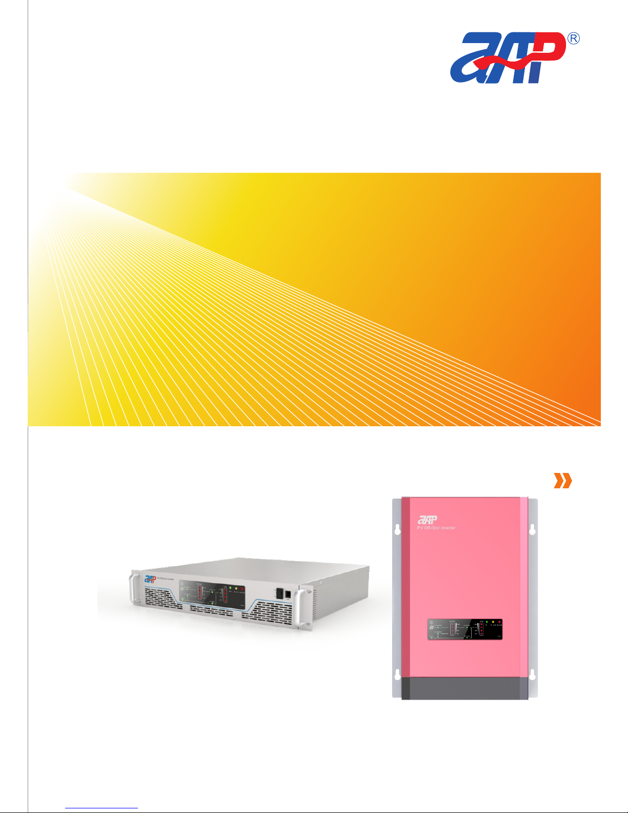
Smart HF Series Single-phase PV Off-grid Inverter
Page 2

1
9
Smart HF Series Single-phase PV Off-grid Inverter
Page 3

說 明
INTRODUCTION
1
9
Part NO. 18950-358-00(PD)
USER MANUAL
APM Technologies (Dongguan) Co., Ltd
Smart HF Series Single-phase PV Off-grid Inverter
Page 4

Foreword -----------------------------------------------------------------------
Precautions -------------------------------------------------- -------------------
1 Production Introduction -------------------------------------------------------- 5
1.1 Product Features ------------------------------------------------------ ----
1.2 Main Specifications ------------------------------------------------ ---------
1.3 System Structure Diagram ---------------------------------------------- ----
2 Display Panels ---------------------------------------------------------------- 9
2.1 Front Panel Display --------------------------------------------------------- 9
2.2 Front Panel LED Display----------------------------------------------------
2.3 Rear Panel Display---------------------------------------------------------
3 System Operation Mode Introduction ---------------------------------------- -
3.1 UPS Mode-----------------------------------------------------------------
3.2 PV Energy Saving Mode----------------------------------------------------
3.3 System Initial Setting--------------------------------------------- --- -------
3.4 Steps for System Mode Setting---------------------------------------------
3.5 Monitoring Software (Optional)---------------------------------------------
3.6 Protection & Malfunction Warning Display----------------------------------
4 Installation and Wiring--------------------------------------------------------
4.1 Battery Connection Cables ------------------------------------------------
4.2 Proposed Battery Pack Configuration --------------------------------------
4.3 Packing List --------------------------------------------- ------------------
4.4 Quick Installation Guide----------------------------------------------- --- -
4.5 Schematic Diagram of System Installation - --------------------------------
4.6 Deduction Amount Usage- --- --- ------------------------------------------
4. 7 Precautions of Load Application ------------------- --- --- --- --------------
5 Common Faults & Solutions ---------------------------------------------------
6 Warranty Statement ---------------------------------------------------------- 32
7 Product Recycling------------------ ------------------------------------------ 36
8 Contact Us------------------------------------------------------------------- 36
Page 5

Table of Contents
Foreword -----------------------------------------------------------------------
Precautions -------------------------------------------------- -------------------
1 Production Introduction -------------------------------------------------------- 5
1.1 Product Features ------------------------------------------------------ ----
1.2 Main Specifications ------------------------------------------------ ---------
1.3 System Structure Diagram ---------------------------------------------- ----
2 Display Panels ---------------------------------------------------------------- 9
2.1 Front Panel Display --------------------------------------------------------- 9
2.2 Front Panel LED Display----------------------------------------------------
2.3 Rear Panel Display---------------------------------------------------------
3 System Operation Mode Introduction ---------------------------------------- -
3.1 UPS Mode-----------------------------------------------------------------
3.2 PV Energy Saving Mode----------------------------------------------------
3.3 System Initial Setting--------------------------------------------- --- -------
3.4 Steps for System Mode Setting---------------------------------------------
3.5 Monitoring Software (Optional)---------------------------------------------
3.6 Protection & Malfunction Warning Display----------------------------------
4 Installation and Wiring--------------------------------------------------------
4.1 Battery Connection Cables ------------------------------------------------
4.2 Proposed Battery Pack Configuration --------------------------------------
4.3 Packing List --------------------------------------------- ------------------
4.4 Quick Installation Guide----------------------------------------------- --- -
4.5 Schematic Diagram of System Installation - --------------------------------
4.6 Deduction Amount Usage- --- --- ------------------------------------------
4. 7 Precautions of Load Application ------------------- --- --- --- --------------
5 Common Faults & Solutions ---------------------------------------------------
6 Warranty Statement ---------------------------------------------------------- 32
7 Product Recycling------------------ ------------------------------------------ 36
8 Contact Us------------------------------------------------------------------- 36
31
30
29
28
23
23
22
22
22
19
19
16
16
15
13
13
11
10
8
7
6
2
0
Page 6

Foreword
HF: Hybrid PV off-gri d inver ters (includes mains complementary/mains
charging function);
HFP: Pure PV off -grid i nvert ers (without mains complementary/mains
charging function);
Rated Output Power;
48: Battery rated voltage input is 48V;
2: Rated Output Voltage 208Vac /220Vac/2 30Vac/240Vac;
PV: P V Off-grid Inverter;
Dea r user, t hank you fo r cho osin g the S mart HF Se ries Single Pha se PV Offgri d Inv erte r dev elop ed by AP M Tech nolo gies (Don ggua n) Co ., Lt d. W e sin cere ly
hop e this s olar i nver ter ca n meet y our re quir emen ts.
All desc ript ions give n in this Us er Ma nual are a ppli cabl e for the f ollowing
mod els of s ingl e phas e PV off -grid inverters:
PV2 48-2 000H FR(W ); P V248 -250 0HFR (W); PV248-30 00HF R(W);
PV2 48-3 500H FR(W ); P V248 -400 0HFR (W); PV248-45 00HF R(W);
All des crip tion s g iven i n this Us er Man ual are a ppli cabl e t o the fo llow ing
mod els of S erie s Sin gle- phas e PV O ff- grid Inve rter ( Pure PV o ff- grid i nver ters ,
wit hout m ains c ompl emen tary o r main s char ging f unct ion) :
PV2 48-2 000H FPR( W); PV24 8-25 00HF PR(W );
PV2 48-3 000H FPR( W); PV24 8-35 00HF PR(W );
PV2 48-4 000H FPR( W); PV24 8-45 00HF PR(W );
Wor ds Exp lana tion:
“ S M A R T ” m e a n s f l e x i b l e a n d i n t e l l i g e n t , “ H F ” m e a n s h i g h - f r e q u e n c y
tra nsfo rmer i sola tion t echn olog y.
Ple ase re ad thi s User M anua l care full y befo re ope rati ng the P V inve rter.
Model Coding:
PV248–3000HF/HFPR(W)
Manual, which shall not be reproduced without permission.
therefore mismatches or wrong descriptions of the products might occur. Please refer
to the actu al p urcha se, down load o r acqui re t he lates t Use r Manua l fro m
www.apmtech.cn or salesperson.
0/36
PROFESSIONAL INNOVATIV E BRAND ING SERVICE
R: Ra ck-mo unted ;
W: Wall- mounted;
Page 7

Rev:PD
May 2016
Declaration
APM Technologies (Dongguan) Co., Ltd has all contents used in this User
Manual, which shall not be reproduced without permission.
The contents of this User Manual will be constantly updated and revised, and
therefore mismatches or wrong descriptions of the products might occur. Please refer
to the actu al p urcha se, down load o r acqui re t he lates t Use r Manua l fro m
www.apmtech.cn or salesperson.
1/36
PROFESSIONAL INNOVATIV E BRAND ING SERVICE
Page 8

Ple ase re ad thi s User M anua l care full y befo re ins tall atio n:
Warning!
Precaution
(1) This sym bol i dent ifie s infor mati on t hat i mpro per o pera tion may re sult in
ser ious i njur y and/ or maj or dam age to t he equ ipme nt.
(2) Only q uali fied e lect rici ans ar e allo wed to i nsta ll and m aint ain th e inve rter.
(3) All th e e lectric in stal lati on nee ds to be c ompl ianc e with t he nat iona l or loca l
law s and st anda rds.
(4) Do not pl ace the P V i nver ter in a hi gh hum idit y e nvir onme nt or adj acen t to a
wat er tow er.
(5) Do n ot place the PV i nver ter in a hig h te mper atur e en viro nmen t, e xpos e to
dir ect su nlig ht or ne ar a fir e loca tion .
(6) When r epla cing t he ba tter y, please use t he bat tery of sam e bran d and
cap acit y. It is p rohi bite d to use the batt ery of differe nt br ands a nd ca paci ties
tog ethe r. N ever p ut the b atte ry or ba tter y bank n earb y a fire s ourc e.
(7) Batt ery aging pro blem is i ncre ased wit h its inc reas ing usag e. On ce t he
agi ng pro blem is sur face d, ple ase has the battery ch ange d by a pr ofes sion al
techn i cian t o avoi d incid e nt o f b attery cell l e a kages t hat may r e s ult in a
spo ntan eous comb ustion. It i s re comm ende d to perf orm a ro utin e mai nten ance &
ins pect ion on t he bat tery.
Smart HF Series Single-phase PV Off-grid Inverter--Precaution
2/36
PROFESSIONAL INNOVATIV E BRAND ING SERVICE
Caution!
(1) This sym bol i dent ifie s infor mati on t hat i mpro per o pera tion may re sult in
med ium in jury a nd/o r dama ge to th e equi pmen t.
(2) Bewa re of hot sur face . T he inve rter wil l b ecom e h ot duri ng oper atio n.
Ple ase av oid co ntac t duri ng ope rati on.
(3) Keep the inve rter 's air inta ke and exha ust pat hs unob stru cted (Not e:
Sho uld ke ep at le ast 15 cm of di stan ce fro m the ba ck and f ront c over s).
(4) Do not plac e any f orei gn o bjec t o n the P V inve rter to a void interrupting
hea t disp ersi on.
dam age to t he equ ipme nt.
sha ll be us ed for f inal i nsta llat ion.
a T N (g roun ded) sys tem. It' s me ans that the tran sfor mer seco ndar y wi ndin g sh all
one circ uit cond ucto r bon ded to ea rth to cr eate a gr ound ed co nduc tor and a n
ear thed sy stem . Exte rnal Mi niat ure ci rcui t brea kers an d Ty pe A RCD sha ll be use d
for t he tra nsfo rmer o utpu t and th en to ho useh old ap plia nces .
for f inal i nsta llat ion.
sha ll b e used . T he b atte ry c ompa rtme nts shal l be at l east b asic i nsulation
bet ween i t's li ve par ts and m etal f rame .
res ista nce de tect ion de vice s hall b e used f or fin al ins tall atio n.
oth erwi se inv erte r dama ge may o ccur.
oth erwi se irr ecov erab le dam age ma y occu r.
dim ), the g ener ator s uppl ies DC v olta ge to th e inve rter.
rat ing.
Page 9

Smart HF Series Single-phase PV Off-grid Inverter--Precaution
3/36
PROFESSIONAL INNOVATIV E BRAND ING SERVICE
Mus t be gro unde d befo re ope rati on.
Onl y qual ifie d elec tric ians a re all owed t o inst all an d main tain t he inv erte r.
Ign orin g t he f ollo wing ins truc tion s c an cause phy sica l i njur y or dea th, or
dam age to t he equ ipme nt.
(1) For A C input s ide: ext erna l Mi niat ure c ircu it b reak ers and Typ e B R CD
sha ll be us ed for f inal i nsta llat ion.
(2) Fo r AC outp ut side : e xter nal fre quen cy tran sfor mer sha ll be used to cre ate
a T N (g roun ded) sys tem. It' s me ans that the tran sfor mer seco ndar y wi ndin g sh all
one circ uit cond ucto r bon ded to ea rth to cr eate a gr ound ed co nduc tor and a n
ear thed sy stem . Exte rnal Mi niat ure ci rcui t brea kers an d Ty pe A RCD sha ll be use d
for t he tra nsfo rmer o utpu t and th en to ho useh old ap plia nces .
(3) Fo r b atte ry ter mina l s ide: Ex tern al Min iatu re circ uit bre aker s shal l b e u sed
for f inal i nsta llat ion.
haz ardo us vol tage a nd en eygy o n batt ery termi nal. B atte ry com part ment s
sha ll b e used . T he b atte ry c ompa rtme nts shal l be at l east b asic i nsulation
bet ween i t's li ve par ts and m etal f rame .
(4) For PV inp ut s ide, Ext erna l M inia ture cir cuit bre aker s a nd Arr ay i nsul atio n
res ista nce de tect ion de vice s hall b e used f or fin al ins tall atio n.
(1) The inve rter inp ut v olta ge does n ot excee d th e ma ximu m in put volt age;
oth erwi se inv erte r dama ge may o ccur.
(2) The po siti ve and nega tive p ole of sola r modu les ca n not b e grou nded,
oth erwi se irr ecov erab le dam age ma y occu r.
(3) When the pho tovoltaic g ener ator cells are exp osed to lig ht ( even if i t is
dim ), the g ener ator s uppl ies DC v olta ge to th e inve rter.
(1) The reco mmen ded sol ar m odul es need to c ompl y w ith IEC6 1730 Clas s A
rat ing.
(2) The in vert ers ar e only f or cry stal line s ilic on sol ar mod ules .
Page 10
HAZ ARDO US VOLTAG E AND E NEYG Y ON B ATTERY T ERMI NAl. B atte ry
com part ment s sh all b e us ed. R isk of fire and sho ck, con nect bat tery te rmin als
pri or to th e turn o ff PV isolators and disconn ect al l AC s witc hs.
Smart HF Series Single-phase PV Off-grid Inverter--Precaution
effective 3 2 - b i t D S P c o n t r o l , a n d a h i g h - f r e q u e n c y t r a n s f o r m e r i s o l a t i o n
tec hnol ogy. T he a djus tmen ts of outp ut v olta ge an d fre quen cy, sw itch over of U PS
mod e o r P V e nerg y s avin g mode ca n a ll be perf orme d f rom the s etti ng keyb oard at
the f ront p anel o r from a m onit orin g soft ware .
ene rgy sav ing mode . The u sers can ad just th ese mod es according to de mand .
Whe n t he UPS m ode is se lect ed, el ectr icit y f rom a lo cal pow er gri d flow s t hrou gh a
byp ass circ uit to all the l oad app lian ces. When the powe r supp ly of l ocal powe r
gri d is no t st able or bei ng s hut dow n, t he load app lian ces wil l ob tain po wer supp ly
from a batte ry bank t hroug h t he PV inver ter, w hich is actin g a s a typi cal
uni nter rupt ible p ower s uppl y syst em.
wil l g ive priority to rech arge the batt ery b ank, and supp ly p ower to al l the l oad
app lian ces a t th e sam e ti me, t hus enab ling the full use of so lar ener gy in ord er to
cut ba ck the amou nt of electricity en ergy fe edin g b y the l ocal po wer grid . O nly
whe n the batt ery pow er is l ower than the bat tery prot ecti on shut down poin t, the
pow er s uppl y w ill be obta ined from t he bypa ss l ocal gr id o r t he i nver ter shu tdow n,
so a s to prol ong t he b atte ry life . User s c an c hoos e t he cor rect op erat ing m ode
acc ordi ng to th eir ow n need s or wea ther c ondi tion s.
pan els and AC lo cal gr id pow er, and ena ble PV i nver ters t o feed t he AC l oads w hile
giv ing a prio rity t o use the e nerg y from s olar pane ls t o char ge t he b atte ry b ank
thr ough MPPT con trol lers , hen ce to ach ieve the g oal o f maximum ene rgy s avin g.
Onl y use a loc al pow er gri d f or bat tery c harg ing wh en the PV en ergy can not
gua rant ee th e ser vice life of ba tter y so a s to f ully ensu re th e bat tery 's sa fety and
ser vice l ife. Insi de th e PV in vert er ar e an in tegr ated sola r MPPT con trol ler an d a
loc al g rid rec harg er, s o t he u sers only nee d to conn ect the PV inve rter with
bat teri es, loc al pow er grid a nd sola r pane ls to set up a gr een energy-saving pow er
sup ply s tati on, whic h c an ful fill th e goal of gr een envi ronm enta l p rote ctio n and
ene rgy sa ving .
4/36
PROFESSIONAL INNOVATIV E BRAND ING SERVICE
Do n ot c arry out any wiring an d in spec tion or c hang ing c ompo nent s wh en the
pow er supp ly is applied. Haza rdou s volt ages may stil l be pre sent in the inv erte r
eve n if the exte rnal c ircu it br eake rs are all sw itch ed of f. Wait at leas t 500 s a fter
swit chin g off t he i nvert er. This e nsure s that the c apac itors a re elec tric ally
dis char ged.
Do no t dispose o f the p rodu ct tog ether wit h hous ehol d was te, bu t only in
acc orda nce wit h the loca lly appl icab le regu lati ons for the dis posa l o f e lect roni c
was te.
Ple ase re ad thi s User M anua l care full y befo re ins tall atio n.
Instructions
Appliance is in compliance with CE standards.
Warning!
Page 11

Product Introduction
1-1
1
Sma rt HF ser ies DC/A C si ne wa ve P V off-grid i nver ters are ado ptin g a h ighl y
effective 3 2 - b i t D S P c o n t r o l , a n d a h i g h - f r e q u e n c y t r a n s f o r m e r i s o l a t i o n
tec hnol ogy. T he a djus tmen ts of outp ut v olta ge an d fre quen cy, sw itch over of U PS
mod e o r P V e nerg y s avin g mode ca n a ll be perf orme d f rom the s etti ng keyb oard at
the f ront p anel o r from a m onit orin g soft ware .
Sma rt HF seri es inve rter has two app lica ble mod es: (1) UPS mode , a nd (2) PV
ene rgy sav ing mode . The u sers can ad just th ese mod es according to de mand .
Whe n t he UPS m ode is se lect ed, el ectr icit y f rom a lo cal pow er gri d flow s t hrou gh a
byp ass circ uit to all the l oad app lian ces. When the powe r supp ly of l ocal powe r
gri d is no t st able or bei ng s hut dow n, t he load app lian ces wil l ob tain po wer supp ly
from a batte ry bank t hroug h t he PV inver ter, w hich is actin g a s a typi cal
uni nter rupt ible p ower s uppl y syst em.
If used th e PV ene rgy sav ing mode to geth er w ith sol ar p anel s, the PV i nver ter
wil l g ive priority to rech arge the batt ery b ank, and supp ly p ower to al l the l oad
app lian ces a t th e sam e ti me, t hus enab ling the full use of so lar ener gy in ord er to
cut ba ck the amou nt of electricity en ergy fe edin g b y the l ocal po wer grid . O nly
whe n the batt ery pow er is l ower than the bat tery prot ecti on shut down poin t, the
pow er s uppl y w ill be obta ined from t he bypa ss l ocal gr id o r t he i nver ter shu tdow n,
so a s to prol ong t he b atte ry life . User s c an c hoos e t he cor rect op erat ing m ode
acc ordi ng to th eir ow n need s or wea ther c ondi tion s.
Sma rt HF seri es pr oduc ts ca n cha rge the b atte ry ba nk th roug h bot h the sola r
pan els and AC lo cal gr id pow er, and ena ble PV i nver ters t o feed t he AC l oads w hile
giv ing a prio rity t o use the e nerg y from s olar pane ls t o char ge t he b atte ry b ank
thr ough MPPT con trol lers , hen ce to ach ieve the g oal o f maximum ene rgy s avin g.
Onl y use a loc al pow er gri d f or bat tery c harg ing wh en the PV en ergy can not
gua rant ee th e ser vice life of ba tter y so a s to f ully ensu re th e bat tery 's sa fety and
ser vice l ife. Insi de th e PV in vert er ar e an in tegr ated sola r MPPT con trol ler an d a
loc al g rid rec harg er, s o t he u sers only nee d to conn ect the PV inve rter with
bat teri es, loc al pow er grid a nd sola r pane ls to set up a gr een energy-saving pow er
sup ply s tati on, whic h c an ful fill th e goal of gr een envi ronm enta l p rote ctio n and
ene rgy sa ving .
Smart HF Series Single-phase PV Off-grid Inverter--Product Introduction
5/36
PROFESSIONAL INNOVATIV E BRAND ING SERVICE
Page 12

Sma rt H F s erie s in vert er has a pure sine wav e o utpu t, a nd it c an cont inuo usly
sup ply 105 % load o utpu t and has t he cap acit y to cope w ith 12 0% sho rt tim e
ove rloa d an d 15 0% i nstantaneous ov erlo ad. The PV inve rter is sui tabl e to use fo r
indu ctive , capac itive a n d othe r h arsh load types . Appli catio n a reas cove rs
c o m p u t e r , c o m m u n i c a t i o n , y a c h t a n d r e c r e a t i o n a l v e h i c l e a n d h o m e
ent erta inme nt dev ices , mot or, powe r dev ice, i ndus tria l con trol e quip ment and
var ious t ypes o f hous ehol d appl ianc es.
1.1 Product Fe a t ures
Pur e sine w ave ou tput ( THD < 3% )
32- bit hi gh ef fici ent D SP co ntro l and high-frequency tra nsfo rmer isol atio n
tec hnol ogy.
Max . effi cien cy is up t o 93%
Rat ed out put po wer: 1 00% lo ad. In stan tane ous ou tput p ower : 150% l oad.
Out put volt age, ef fici ency an d op erat ing mode ar e ad just able via th e fr ont
pan el or re mote m onit orin g.
Bui lt-i n inpu t and ou tput b ypas s prot ecti on fun ctio ns.
UPS a nd PV en ergy -sav ing mo des th at can e asil y be swi tche d over.
Equ ippe d w ith a controllable b ypas s f or loca l grid powe r output, and the
swi tch- over t ime be twee n the gr id and P V inve rter i s ≦10ms (Typ.) .
Vis ual LE D disp lay of t he com plete operating sta tus.
Low b atte ry pow er war ning a larm a nd ind icat ion.
MPP T cont rol, h igh ch arging effici ency w ith th e char ging c urre nt of up t o 50A.
RS4 85 rem ote mo nito ring f unct ion (O ptio nal) .
2-y ear pr oduc t warr anty.
Smart HF Series Single-phase PV Off-grid Inverter--Product Introduction
1.2 Main Speci f i cations
6/36
PROFESSIONAL INNOVATIV E BRAND ING SERVICE
Page 13
1.2 Main Speci f i cations
Smart HF Series Single-phase PV Off-grid Inverter--Product Introduction
7/36
PROFESSIONAL INNOVATIV E BRAND ING SERVICE
Specifica tio ns for the Smart H F Ser ies Single-p has e PV Off -gr id Inverter
Models
PV248-200 0HF W
PV248-200 0HF R
PV248-200 0HF PW
PV248-200 0HF PR
PV248-250 0HF W
PV248-250 0HF R
PV248-250 0HF PW
PV248-250 0HF PR
PV248-300 0HF W
PV248-300 0HF R
PV248-300 0HF PW
PV248-300 0HF PR
PV248-350 0HF W
PV248-350 0HF R
PV248-350 0HF PW
PV248-350 0HF PR
PV248-400 0HF W
PV248-400 0HF R
PV248-400 0HF PW
PV248-400 0HF PR
PV248-450 0HF W
PV248-450 0HF R
PV248-450 0HF PW
PV248-450 0HF PR
PV Input
Vmax PV(Vd. c.)
Isc PV(A)
PV input operating voltage
range(Vd.c.)
Full load M PPT range
(Vd.c.)
Maximum operating PV
input c urrent (A)
Max. inverter backfeed
current to the arra y (A)
RechargingEfficienc y
95V
50A
60-95V
75-95V
41A
96.5%
AC output
Nominal A C output voltage
(Va.c.)
Adjustable AC output
voltage (Va.c.)
Nominal A C output
frequency (Hz)
Wave Type
Effici encies
Maximum continuous AC
output powe r (VA)
Maximum continuous AC
output curr ent (A)
Power f actor range
Maximum output fault
current
Maximum output over
current protection
Protections
230 Va.c.
208 Va.c. /22 0 Va.c. /23 0 Va.c./24 0 Va.c.
50 Hz
Pure sine wav e (TH D < 3.0%)
Max. 93%
2500VA 3000VA 3500VA 4 000 VA 4500VA
9A 11.5 A 14A 1 6.5A 19A 21 .5A
1 1 1 1 1 1
18A 23A 28A 33A 3 8A
43A
13.5A 17 A 21 A 25 A 28 .5A
32A
SCP, O LP & OPT
AC input
Nominal A C input voltage
(Va.c.)
Nominal A C input
frequency (Hz)
Maximum continuous AC
input p ower (VA)
Maximum continuous AC
input c urrent (A)
230 Va.c.
50 Hz
2000VA 2500VA 3000VA 3500VA 4 000 VA 4500VA
9A 11.5 A 14A 16.5A 19A 21.5A
Remark: The above AC inp ut parameters are n ot applicable to th e inverters denot ing by HFP
Battery ter min al (Charging m ode )
Nominal charging voltage
(Vd.c.)
Charging voltage range
(Vd.c.)
Nominal charging current
(A)
Maximum continuous
charging current (A)
Maximum continuous
charging power (W)
55±0.4V
43-55V
45A
50A
2400W
Battery ter min al (Discharg ing m ode)
Nominal discharge voltage
(Vd.c.)
Nominal discharge current
(A)
Maximum continuous
discharging current (A)
48V
41.7A 52. 5A 62.5A 73 A 8 3.5A 94 A
46.5A 58. 5A 70A 81.5A 93 A 1 05A
65A
2000VA
Page 14
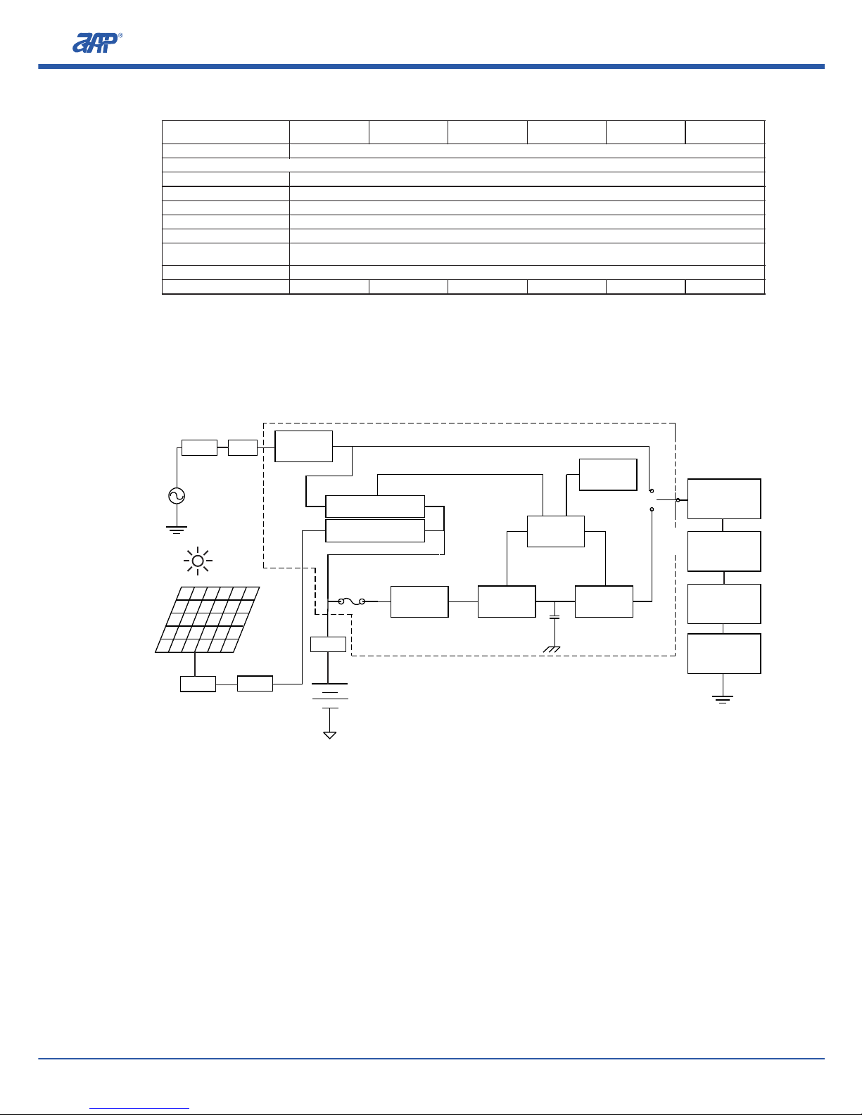
1.3 System Block Diagram
Solar Panel
AC Input
Polarity
Detection
AC Charger
Solar Charger
AC Output
Battery
Fuse
LOAD
EMI
Filter
DC/DC
Converter
DC/AC
Inverter
CPU
Controller
LED
F -
igure1 1 System Block Diagram
Display
Smart HF Series Single-phase PV Off-grid Inverter--Product Introduction
2.1 Front Panel
A
B
C
D
E
8/36
PROFESSIONAL INNOVATIV E BRAND ING SERVICE
Maximum continuous
discharging power (W)
Protections
2000W 2 500W 3 000 W 3500W 4000W 4500W
General par ame ters
OCP, B attery RC P, Low batt ery a utomati c ala rm, Low bat ter y automat ic cu toff .
Protective class
Ingress protection (IP)
Relative humidity range
Allowable Altitude
Storage temperature range
Ambient service
temperature range
Dimension Reference
Weigh t Reference
I
IP2 0
5 % to 85 % (Non c ond ensing)
2000m (F or ov er 2000m, t he ra ted power d ecr eases 10% b y eve ry 1000m dr op) .
-40℃ to +85℃
-20℃ to +40℃, I ndo or, condit ion ed
482.6× 88. 9×450.0 mm( rack-mo unt ed);347 ×47 5×165mm (wa ll-moun ted )
16Kg 16Kg 18 Kg 1 8Kg 1 8Kg 1 8Kg
MCCB
RCD
MCCB
IRDD
MCCB
Frequ enc y
Tra nsf ormer
MCCB
RCD
Page 15

2
Display Panel Introduction
2.1 Front Panel
A
B
C
D
E
Figure 2.1.1: Overview of the front panel for rack-mounted smart HF series PV off-gridinverter
D
E
A
B
C
A
B
C
Figure 2.1.2: Overview of the front panel for wall-mounted smart HF series PV off-grid inverter
RS4 85 co mmun icat ion p ort: Opti onal RS48 5 con nect ing w ire t o con nect with
a PC fo r remo te mon itor ing.
POW ER O N/OF F swi tch: When s witc h i s at “ON” p osit ion the i nver ter is
ope rati ng, wh erea s when i t is at “O ff” posit ion th e inve rter i s shut d own.
LED d ispl ay pane l: Dis play th e opera ting co ndit ion, lo ad capa city, ba tter y
vol tage a nd oth er inf orma tion o f the in vert er.
Set ting : w ork mode, out put vol tage , freq uenc y a nd powe r savi ng mode , and
oth er fun ctio n sett ings .
Air inta ke h ole: For hea t d issi pati on, con tinu ous ven tila tion must be k ept to
ens ure a st able p rodu ct ope rati on.
Smart HF Series Single-phase PV Off-grid Inverter--Display Panel Introduction
9/36
PROFESSIONAL INNOVATIV E BRAND ING SERVICE
Page 16

A
B
C
AC LIN E: If the LED i ndic ator of lo cal pow er grid is o n, that im plie s c onne ctio n
wit h th e po wer g rid and t hat the s tatu s is nor mal. If the LED is fla shin g, it
imp lies a co nnec tion is made yet an abno rmal sta tus of the po wer grid occ urs
(ov er vol tage , unde r volt age or e xcee d stab le vol tage r ange ).
AC CHARGE: I f the LE D indi cato r of loca l powe r grid c harg er is on, t hat
imp lies t he bui lt-i n A C char ger is char ging a b atte ry. If t he LED is fla shin g, it
imp lies t he AC inpu t is ava ilab le yet t he AC cha rger is not operating .
PV CH ARGE : If the LE D indi cato r of Sol ar MPP T char ging c ontr olle r is on, t hat
imp lies the solar p anel s a re char ging to the bat tery bank thro ugh the MPP T
bui lt in th e PV inv erte r. I f the LE D is fla shin g, it im plie s the PV i nput i s
LED d ispl ay pa nel: To dis play the op erat ing s tatu s, loa ding capa city, b atte ry
vol tage a nd oth er inf orma tion .
Fun ctio n set ting butt on: Ope rati on mode, output volt age, freq uenc y a nd
pow er sav ing mo de, an d othe r func tion s etti ngs.
Wa ll mou ntin g hole .
2.2 Front Pane l L E D Display
LED Display
Loading
LED 1 ON
0~25%
LED 1~2 ON
26%~50%
LED 1~3 ON
51%~75%
LED 1~4 ON
76%~100%
LOAD: Output load indicators display the existing load capacity.
AC LINE
AC CHARGE
PV CHARGE
BATTERY
100%
75%
50%
25%
100%
75%
50%
25%
LOAD
INVERTER
BY PASS
Run
Min.ALM
Maj.ALM
Setting
Figure 2.2: Front Panel LED Display
BATTERY: Battery capacity indicators display the battery residual capacity.
LED Display
Battery Capacity
LED 1 ON
0~25%
LED 1~2 ON
26%~50%
LED 1~3 ON
51%~75%
LED 1~4 ON
76%~100%
Smart HF Series Single-phase PV Off-grid Inverter--Display Panel Introduction
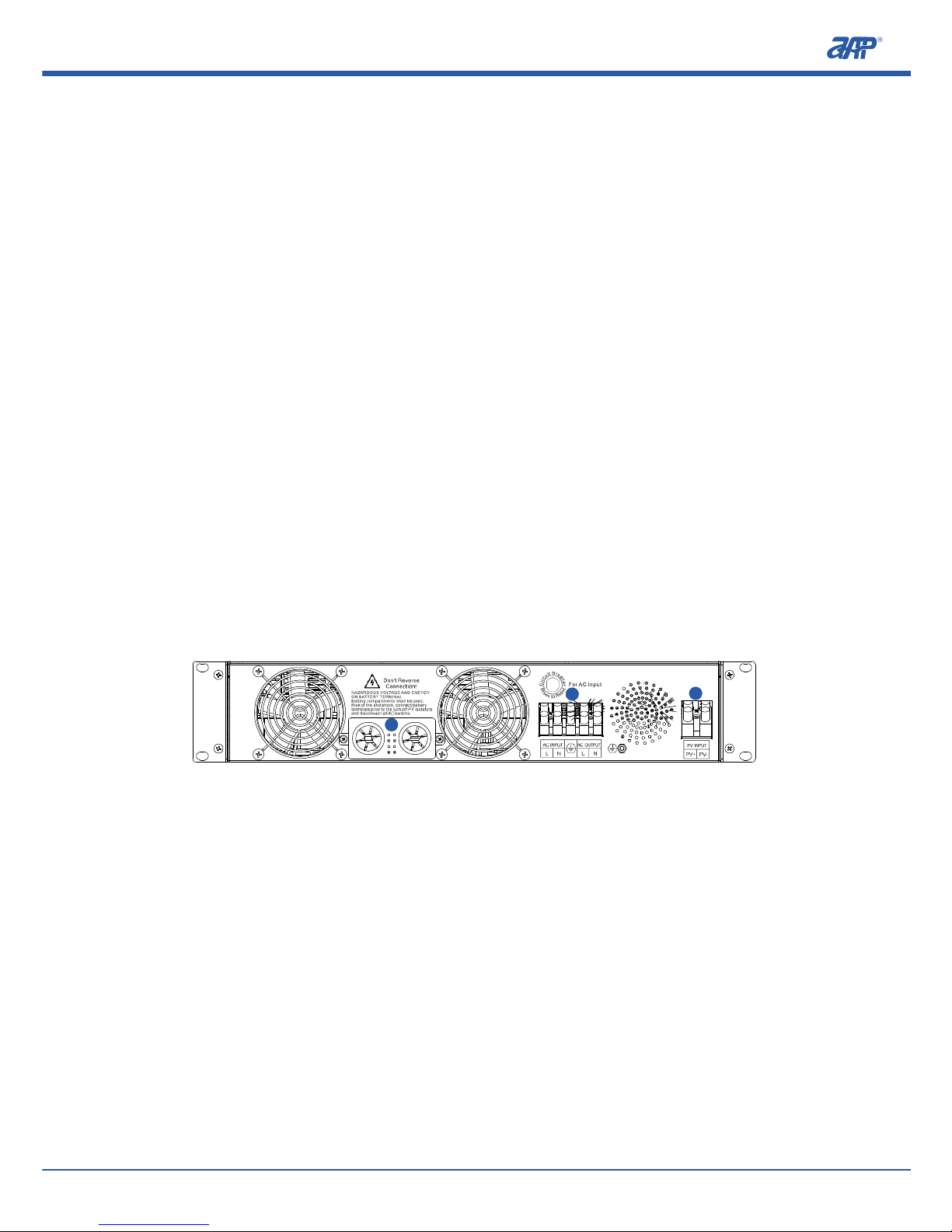
2.3 Rear Panel Display
A
B
C
D
E
10/36
PROFESSIONAL INNOVATIV E BRAND ING SERVICE
Page 17

ava ilab le yet t he PV co ntro ller i s not op erat ing.
INV ERTE R: I f the LED indi cato r of i nver ter mode is on, t hat impl ies the PV
inv erte r is converting e lect rici ty f rom the bat tery b ank to the AC outp ut a nd
fee d to the l oads .
BY PASS: Byp ass powe r ind icat or w ith the “ON” imp lyin g th e lo cal p ower gri d
thr ough t he bui lt-i n rela y in PV in vert er is fe edin g the lo adin g devi ces.
RUN : PV inve rter 's o pera ting ind icat or w ith the “ON” imp lyin g the PV inve rter
is s tart ed a nd a t a n orma l op erat ing stat us that i t ca n su pply an AC volt age to
the l oadi ng dev ices .
Min . ALM: PV inve rter 's w arni ng i ndic ator with the “ ON” impl ying a warn ing
not ice that to be handled with out dela y. There wil l be int ermi tten t al arm go off
to remi nd t he user s desp ite the P V i nver ter can stil l s uppl y outp ut powe r to
loa ding d evic es.
Maj . ALM : P V i nver ter' s m alfu ncti on indi cato r with the “ON ” i mply ing the PV
inv erte r ca nnot op erat e norma lly due to a fa ult that th e user is requ ired to
tro uble shoo t the is sue im medi atel y.
2.3 Rear Panel Display
A
B
Figure 2.3.1: Overview of the rear panel for rack-mounted smart HF series PV off-grid inverter.
A
C
D
B
C
D
E
E
Inp ut a nd O utpu t Term inal s: I nclu ding the loc al p ower gri d AC i nput ter mina ls
(L, N ), inv erte r AC o utpu t term inal s (L, N) , and gr ound ing te rmin al.
PV In put Te rmin al (PV +, PV-).
Bat tery I nput Termi nals (BAT+, B AT- ).
Fan E xhau st Vent.
Ove rcur rent p rote ctio n devi ce for l ocal p ower i nput .
Smart HF Series Single-phase PV Off-grid Inverter--Display Panel Introduction
11/36
PROFESSIONAL INNOVATIV E BRAND ING SERVICE
A
Page 18

A
B
C
D
E
Figure 2-3-2 Rear Panel Overview (Wall -moun ted)
B E
D
C
A
D
F
G
F
G
Inp ut and Out put Ter mina ls: Inc ludi ng loca l p ower gri d AC inp ut term inal
(L, N), in vert er AC outp ut ter mina l (L,N ), and g roun ding t ermi nal.
PV In put Te rmin al (PV +, PV-)
Bat tery I nput Termi nal (BAT+, BAT-)
Exh aust Ven t of Fan
POW ER ON/ OFF s witc h: Swi tch t o the “ ON” po sition to start the PV inve rter,
whe reas s witc h to the “ OFF” p osit ion to t urn off the P V inve rter.
RS4 85 int erfa ce.
Ove rcur rent p rote ctio n devi ce for m ains p ower i nput .
Smart HF Series Single-phase PV Off-grid Inverter--Display Panel Introduction
out put inv erte r w ith dig ital and hi gh effi cien t m icro con trol ler (CP U). Th e P V
inv erte r has b oth UPS mo de and PV savi ng ener gy mode , w hich al lows the us er to
swi tch oper atio n mod e ba sed on own ne eds. The PV inve rter 's facto ry defau lt
set ting is PV po wer sav ing mode, but th e u sers ca n r eset it t o U PS mode th roug h a
manu a l a djustm e nt (Plea s e r efer t o S ection 3.4 f o r d etail e d o perat i on) o r
mon itor ing sof twar e (opt iona l) base d on the en viro nmen tal and p ower sup ply
con diti ons.
pro port ion of ener gy savi ng. When PV invert er i s s et a t t he UPS mode an d a s lo ng
the pow er grid ca n ma inta in a n orma l el ectr icit y s uppl y, th e P V i nver ter will sw itch
ove r t o a b ypas s mode for supp lyin g powe r to load s, and cons eque ntly t he
pro port ion of ener gy savi ng i s r athe r l ow. On th e o ther hand, when th e PV in vert er
is s et a t t he P V p ower savin g m ode, the PV i nver ter w ill take pr iori ty usi ng the
sol ar po wer sour ce, a nd conse quen tly t he propo rtio n of ener gy sa ving is v ery
hig h. Only wh en the PV ener gy inpu t i s not a vail able , a nd the b atte ry p ower is
cri tica lly low w ill th e P V inve rter s witc h o ver to t he powe r grid f or a powe r supp ly. If
the p ower supp ly from a powe r g rid is not avai labl e a t thi s time , t he syst em w ill
aut omat ical ly shu t down .
3.1 UPS Mode
12/36
PROFESSIONAL INNOVATIV E BRAND ING SERVICE
Page 19

3
System Operation Mode Introduction
Sma rt HF Series S ingl e-ph ase PV Off-gr id Inve rter is a DC/ AC pure sin e w ave
out put inv erte r w ith dig ital and hi gh effi cien t m icro con trol ler (CP U). Th e P V
inv erte r has b oth UPS mo de and PV savi ng ener gy mode , w hich al lows the us er to
swi tch oper atio n mod e ba sed on own ne eds. The PV inve rter 's facto ry defau lt
set ting is PV po wer sav ing mode, but th e u sers ca n r eset it t o U PS mode th roug h a
manu a l a djustm e nt (Plea s e r efer t o S ection 3.4 f o r d etail e d o perat i on) o r
mon itor ing sof twar e (opt iona l) base d on the en viro nmen tal and p ower sup ply
con diti ons.
The m ain d iffe rence bet ween UPS mo de an d PV po wer sa ving mode is in t he
pro port ion of ener gy savi ng. When PV invert er i s s et a t t he UPS mode an d a s lo ng
the pow er grid ca n ma inta in a n orma l el ectr icit y s uppl y, th e P V i nver ter will sw itch
ove r t o a b ypas s mode for supp lyin g powe r to load s, and cons eque ntly t he
pro port ion of ener gy savi ng i s r athe r l ow. On th e o ther hand, when th e PV in vert er
is s et a t t he P V p ower savin g m ode, the PV i nver ter w ill take pr iori ty usi ng the
sol ar po wer sour ce, a nd conse quen tly t he propo rtio n of ener gy sa ving is v ery
hig h. Only wh en the PV ener gy inpu t i s not a vail able , a nd the b atte ry p ower is
cri tica lly low w ill th e P V inve rter s witc h o ver to t he powe r grid f or a powe r supp ly. If
the p ower supp ly from a powe r g rid is not avai labl e a t thi s time , t he syst em w ill
aut omat ical ly shu t down .
3.1 UPS Mode
Whe n th e PV in vert er i s st arte d b y a user, it will aut omat ical ly u se the bypa ss
mod e to sup ply electri city ene rgy dire ctly to the loa ding dev ices . At this tim e,
the s olar c harg er is c harg ing the bat tery w hile the ma ins ch arge r is sh ut
dow n. If the sol ar c harg er i s no t in ope rati on, then the mai ns charg er will
mak e j udgm ent ac cord ing to the ba tter y volt age sam plin g valu e for whe ther
or n ot t o c harg e the batt ery. I f the b atte ry v olta ge fal ls below the star t
thr esho ld vo ltag e of t he ma ins char ger a t 50V, the main s cha rger will char ge
the ba tter y a ll the tim e. If the ba tter y v olta ge is higher tha n t he star t t hres hold
vol tage o f the ma ins ch arge r, t hen th e main s char ger wi ll not w ork.
Smart HF Series Single-phase PV Off-grid Inverter--System Operation Mode Introduction
13/36
PROFESSIONAL INNOVATIV E BRAND ING SERVICE
Page 20

Whe n th e ba tter y ca paci ty i s fu lly char ged to 5 5V, t he s olar cha rger wil l en ter
the floa ting char ge state to char ge th e bat tery. At this poin t, it is st ill the
byp ass mo de to su pply p ower t o the lo ads.
If the main s po wer outa ge h appe ned inst anta neou sly or t he m ains pow er has
exc eede d th e co nstant volt age inpu t r ange , th e PV in vert er w ill automatically
and immediately swit ch ove r to the i nver ter output po wer so a s to rep lica te the
pow er sup ply of l oading de vice s, and g uara ntee that t here i s no in terr upti on
or dama ge to the devi ces cau sed by an unst able main s p ower or p ower
out age, and he nce subs eque ntly ca usin g un nece ssar y econo mic loss es to
the u sers .
If th e main s pow er is re stored to a normal con diti on, th e PV in vert er wil l
aut omat ical ly s witc hes to the byp ass mode and res ume main s p ower t o t he
loa ds.
If the ma ins pow er rema ins cut off an d i n t he case of th e P V c harg ing ene rgy is
les s tha n the ener gy required by loa ds, the volt age of bat tery will grad uall y
dec reas e. W hen the batter y vo ltag e i s be low 45V,t he PV i nver ter wil l ra pidl y
sta rt bee ping an ala rm at a f requ ency of abo ut 1 se cond a t a tim e. Whe n the
bat tery i s almo st dra ined c ompl etel y, the PV i nver ter is a bout t o shut d own.
Whe n bat tery vol tage fall s to 43V, the batt ery p ower is almo st co mple tely
dra ined . I f the ma ins pow er is still not a vail able at thi s time , t he PV in vert er
wil l automatically s hut down its out put. A t thi s st age, the PV inve rter rema ins
in a st andb y mo de a nd w aiti ng f or t he m ains pow er t o re stor e an d th e input of
PV en ergy.
If the user t urns the PV in vert er's powe r s witc h to the “OF F” posi tion a t t his
mom ent, th e inve rter is s hut down completel y. The u ser need s to manu ally
tur n t he power sw itch of PV in vert er to the “ON ” p osit ion in ord er to r estart the
inv erte r. If th e P V i nver ter sta ys in a stan dby mod e a nd when th e m ains po wer
is rest ored , the inve rter w ill aut omat ical ly s witc h to the bypa ss mode to
sup ply powe r for the l oads . T he P V i nver ter will also sta rt t o use t he m ains
pow er cha rger t o char ge the b atte ry so as t o prol ong th e serv ice li fe of ba tter y.
If the mai ns p ower su pply rem ains cutoff bu t PV en ergy inp ut is a vail able , the
PV i nver ter w ill a utom atic ally t urn o n the s olar char ger to rech arge t he
bat tery, an d at this s tage the PV inv erte r has no ou tput . W hen th e s olar
charger h a s c h arged the battery v o l tage to 5 2V, t h e P V inverte r will
aut omat ical ly in itia te t he inver ter o utpu t po wer for supplying pow er to the
loa ds.
Smart HF Series Single-phase PV Off-grid Inverter--System Operation Mode Introduction
Remarks:
(1)
(2)
(3)
3.2 PV Energy Saving Mode
14/36
PROFESSIONAL INNOVATIV E BRAND ING SERVICE
Page 21

UPS m ode is n ot ava ilab le for H FP series products.
Whe n the mains p ower s uppl y is cut off , the P V inv erte r's outp ut p ower
sup plyi ng time i s depe nded on the b atte ry cap acit y a nd the a moun t of load s
bei ng use d.
The adva ntag e of UPS m ode is th at the ba tter y cap acit y wi ll ge nera lly be
mai ntai ned at a l evel h ighe r tha n 90% in o rder t o ensure an a dequ ate po wer
sup ply to th e load ing devices i n the ev ent of a sh ort period ut ilit y powe r
out age. As t he numb er of deep disc harg e of the bat tery is redu ced, and the
bat tery se rvic e l ife is clo sely re late d t o t he numbers of de ep disc harg e, henc e
the U PS mo de can significantl y exte nd the serv ice li fe of b atte ry. Sin ce UP S
mod e is o f lo w ene rgy s avin g ef fici ency, it i s sui tabl e to use i n pla ces like the
com merc ial off ices and re side ntia l ar eas wher e the m ains po wer supp ly is
ava ilab le and r elat ivel y stab le.
Remarks:
(1)
(2)
(3)
3.2 PV Energy Saving Mode
Aft er th e use r sta rts up th e PV i nver ter, it will aut omat ical ly sw itch to th e
inv erte r ou tput to supp ly p ower to the loa ding dev ices , an d st art the sol ar
cha rger t o char ge the b atte ry.
Whe n the PV char ging ener gy i s lower t han the e nerg y re quir ed b y the loa ds,
the ba tter y v olta ge wil l g radu ally de crea se. Whe n the bat tery vo ltag e is belo w
45V, the PV inv erte r w ill start rap id beep ing al arm at a fre quen cy of abo ut 1
bee p p er seco nd to alert th e u sers th at the bat tery po wer is abo ut to run out . I f
the m ains p ower i nput i s norm al, th en the PV inv erte r will s tart o ff th e main s
pow er cha rger t o char ge the b atte ry.
Whe n the bat tery vol tage fal ls t o 43 V, th e ba tter y pow er i s al most exh aust ed.
If the inp ut o f m ains powe r is norm al at t his tim e, t he PV inve rter w ill
aut omat ical ly s witc h to t he b ypas s mode so as t o allo w the main s powe r to
sup ply t he load ing d evic es. T he PV inv erte r at the same ti me will st art t he
mai ns power char ger fo r char ging t he batt ery. If s olar charger has ch arge d the
bat tery, then shu t do wn t he ma ins char ger as t he p urpo se of ene rgy savi ng i s
ach ieve d. If th e main s powe r inpu t is not a vail able a t this s tage , the PV
Smart HF Series Single-phase PV Off-grid Inverter--System Operation Mode Introduction
15/36
PROFESSIONAL INNOVATIV E BRAND ING SERVICE
Page 22

inv erte r is sti ll i n a stan dby mode at this mom ent, and is wait ing for the main s
pow er to re stor e and th e inpu t of PV en ergy.
Whe n th e b atte ry volt age is char ged to 52V, the PV inv erte r w ill auto mati call y
swi tch ba ck to th e inve rter p ower o utpu t to sup ply po wer to t he loa ds.
Remark:
The adva ntag e of PV p ower sav ing mode is t o ma xima lly supp ly po wer to
loa ding d evic es by usi ng sol ar ene rgy, while the m ains p ower i s only u sed as a
back up p ower s upply u nder e xtre me cond itio ns. A ccor dingl y, PV p o wer
sav ing m ode is s uita ble to use at the pla ces wher e the mai ns p ower sup ply i s
uns tabl e o r u nava ilab le, suc h a s i n t he remote mountain area s, plat eau,
yac hts, vehi cles , e tc. How ever, batter ies mig ht stay in a r elatively low lev el
und er ext reme weat her condi tion s for a long time . The refo re, we sugg est
use rs to m anua lly s witc h the mode int o U PS and w ait for a be tter wea ther
con diti on bef ore sw itch i t back t o a PV mod e.
3.3 System Initial Setting
All ser ies of pr oduct mo dels con tain ed i n th is U ser Manu al a re h avin g th e
inv erte r out put o f 230 V/50 Hz in the PV po wer savin g mod e as f acto ry de faul t
set ting . User s can adjust the sett ing va lues via the fro nt pa nel “S etti ng” f unct ion
key s (Ref er to Secti on 3.4 f or set ting proc edur e) to su it di ffer ent e nvir onme nt or
ind ivid ual ne eds. Af ter t he new sett ing i s com plet ed, th e PV i nver ter needs t o be
swi tche d off and then restarte d, and the u ser' s sett ing valu es a re s aved as the
ini tial s etti ng val ues. And i n the su bseq uent r eset , the la st set ting v alue s will b e
app lied a s the sy stem i niti al set ting v alue s.
3.4 Steps for System Mode Setting
The 1st layer is a n un inte rrup ted m ode (UPS mode ) and the PV p ower savi ng
mod e sett ings t hrou gh the f ollo wing s teps :
Smart HF Series Single-phase PV Off-grid Inverter--System Operation Mode Introduction
pac k must b e conn ected t o the inve rter, wher eas the main s powe r inp ut c an b e
con nect ed or not b e connected a nd no load s should be connecte d wi th the P V
inv erte r.
and wait for the LED disp lay to l ight up, p ress and h old the “Set ting ” butt on f or
abo ut 5 s econ ds wit h a no -con duct ive to ol, and wa it until the PV inv erter soun ding
a long beep ing ala rm befo re rele asin g t he sett ing but ton. It is an indi cati on that
the PV in verter h as entered to the setu p p rogram, in which the L OAD LED 1 is
lig hted a s an imp lica tion o f the PV i nver ter is a t the 1s t laye r sett ing.
ope rati on. If the LED ligh t indic ator sho ws i t is th e co rrec t mo de of opera tion ,
ple ase press and h old th e “Set ting ” butt on for ab out 3 – 5s , u ntil t he PV in vert er
mak ing a b eep soun d and entering to t he 2 nd leve l outp ut v olta ge s etti ng
(LO ADLE D2 is lig hted ). If not , p leas e pres s and hol d the “Se ttin g” but ton for a bout
1s th en rel ease . The light signal chan ges at e ach pr ess, a nd aft er adj usti ng it to
the req uire d m ode, pr ess the “Se ttin g” butt on for abo ut 3 – 5s unt il t he PV inve rter
is maki ng a bee p so und to i ndic ate the comp leti on o f se ttin g. At this tim e, r elea se
the “Set ting ” but ton t o ent er to the 2 nd la yer o f out put v olta ge se ttin g. T he LO AD
LED 2 i s ligh ted me ans th at the P V inve rter i s ente ring t o the 2n d laye r sett ing.
det ermi ne whet her a d esir able ou tput vo ltag e i s b eing se lect ed. If the sel ecti on is
cor rect , pl ease pres s an d ho ld t he “ Sett ing” but ton f or 3 – 5 s un til the P V in vert er
sou nds a b eep befo re ente ring to t he 3rd laye r o utpu t frequency s etti ng (LOA D
LED 2 i s ligh ted) . If not , plea se fol low St ep 2 for s etti ng the o utpu t volt age.
rel ease i t. In th is way, t he lig ht sig nal ch ange s for ea ch pre ss (Ch ange o f orde r:
208 V→22 0V→2 30V→ 240V ). And whe n adju stin g it unt il the r equi red vo ltag e
16/36
PROFESSIONAL INNOVATIV E BRAND ING SERVICE
Page 23

Ste p 1: Whe n re set the PV i nver ter, p leas e tu rn i t off b efor ehan d. The batt ery
pac k must b e conn ected t o the inve rter, wher eas the main s powe r inp ut c an b e
con nect ed or not b e connected a nd no load s should be connecte d wi th the P V
inv erte r.
Ste p 2: Af ter turn ing on the PV inve rter 's p ower swit ch t o the “ ON” pos itio n
and wait for the LED disp lay to l ight up, p ress and h old the “Set ting ” butt on f or
abo ut 5 s econ ds wit h a no -con duct ive to ol, and wa it until the PV inv erter soun ding
a long beep ing ala rm befo re rele asin g t he sett ing but ton. It is an indi cati on that
the PV in verter h as entered to the setu p p rogram, in which the L OAD LED 1 is
lig hted a s an imp lica tion o f the PV i nver ter is a t the 1s t laye r sett ing.
Ste p 3 : Plea se ref er to Table 3.1 t o deci de whet her it i s a d esir able mod e o f
ope rati on. If the LED ligh t indic ator sho ws i t is th e co rrec t mo de of opera tion ,
ple ase press and h old th e “Set ting ” butt on for ab out 3 – 5s , u ntil t he PV in vert er
mak ing a b eep soun d and entering to t he 2 nd leve l outp ut v olta ge s etti ng
(LO ADLE D2 is lig hted ). If not , p leas e pres s and hol d the “Se ttin g” but ton for a bout
1s th en rel ease . The light signal chan ges at e ach pr ess, a nd aft er adj usti ng it to
the req uire d m ode, pr ess the “Se ttin g” butt on for abo ut 3 – 5s unt il t he PV inve rter
is maki ng a bee p so und to i ndic ate the comp leti on o f se ttin g. At this tim e, r elea se
the “Set ting ” but ton t o ent er to the 2 nd la yer o f out put v olta ge se ttin g. T he LO AD
LED 2 i s ligh ted me ans th at the P V inve rter i s ente ring t o the 2n d laye r sett ing.
PV Saving Mode
(Initial setting)
Run
Min.ALM
Maj.ALM
Run
Min.ALM
Maj.ALM
Uninterrupted
Mode (UPS mode)
Bright
Dark
Table3.1: Operation mode LED display
The 2 nd lay er out put vo ltag e sett ing is d escr ibed a s foll ows:
Ste p 1 : Please refe r t o the L ED sign al c ompa riso n d etai led i n Tabl e 3.2 t o
det ermi ne whet her a d esir able ou tput vo ltag e i s b eing se lect ed. If the sel ecti on is
cor rect , pl ease pres s an d ho ld t he “ Sett ing” but ton f or 3 – 5 s un til the P V in vert er
sou nds a b eep befo re ente ring to t he 3rd laye r o utpu t frequency s etti ng (LOA D
LED 2 i s ligh ted) . If not , plea se fol low St ep 2 for s etti ng the o utpu t volt age.
Ste p 2: P leas e pre ss an d ho ld th e “Se ttin g” bu tton for a bout 1s and th en
rel ease i t. In th is way, t he lig ht sig nal ch ange s for ea ch pre ss (Ch ange o f orde r:
208 V→22 0V→2 30V→ 240V ). And whe n adju stin g it unt il the r equi red vo ltag e
Smart HF Series Single-phase PV Off-grid Inverter--System Operation Mode Introduction
17/36
PROFESSIONAL INNOVATIV E BRAND ING SERVICE
Page 24

set ting is obt aine d, p ress th e “S etti ng” but ton for abo ut 3 - 5s unti l th e P V in vert er
mak ing a b eep t o ind icat e the c ompl etio n of s etti ng. A t this time , rel ease the
“Se ttin g” butto n to ente r th e 3r d la yer o f ou tput fre quen cy s etti ng ( LOAD LED 3 is
lig hted ).
Table 3.2: Voltage Setting LED Display
Light
Output
Run
Min.ALM
Maj.ALM
208Vac
220Vac
230Vac
240Vac
Bright
Dark
(Note: Default Setting is AC 230V)
Voltage
The 3 rd lay er is th e outp ut fre quen cy set ting a s desc ribe d belo w:
Ste p 1: Pleas e refer to the LED si gnal co mpar ison detail ed in Tabl e 3.3 to
det ermi ne w heth er the set ting is of a desir ed o utpu t frequ ency. I f it is cor rect ,
ple ase p ress and ho ld th e “Se ttin g” bu tton for 3 – 5s u ntil the P V inverte r emits a
bee p b efor e c ompl etin g t he freq uenc y setti ng, and enter the pre view mo de, whi ch
mea ns R un, Min .ALM a nd Maj. ALM will be a ll ligh ted, L OAD LED 1~4 is ligh ted,
and 10 s l ater, th e i nver ter wil l be auto mati call y r esta rted . Then t he inve rter ou tput
wil l be b ased on the la test sett ing v alue s. If not , ple ase f ollo w the Step 2 fo r
set ting t he out put fr eque ncy.
Ste p 2: Pl ease pres s and hold the “Sett ing” button for abou t 1s a nd th en
rel ease it. In thi s wa y, th e li ght sign al chan ges for each pre ss. And a fter adj usti ng
it to the re quir ed freq uenc y, p ress th e “ Sett ing” bu tton fo r a bout 3 – 5s unti l t he PV
inv erte r s ound ing a beep to indi cate the com plet ion of fr eque ncy set ting (LOA D
LED 4 i s ligh ted impl ying th e comp leti on o f s etti ng), A t this ti me, rest art the P V
inv erte r to save the set ting s, and the inv erte r o utpu t wil l be base d o n the l atest
set ting v alue s.
Run
Min.ALM
Maj.ALM
Bright
Dark
50Hz
60Hz
(Note: Default Setting is 50Hz)
Light Status
Table 3.3: Frequency Setting LED Display
Output
Frequency
status
Smart HF Series Single-phase PV Off-grid Inverter--System Operation Mode Introduction
Pre view m ode se ttin g is des crib ed as fo llow s:
3.5 Monitoring Software (Optional)
out put v olta ge, freq uenc y and the volt age c onve rsio n se ctio ns by connecting t he
inv erte r R S485 po rt with a com pute r. Pleas e r efer to ou r w ebsi te or cont act a loc al
dea ler fo r more i nfor mati on.
3.6 Protection and Malfunction Warning Display
bat tery inpu t ter mina l wil l blo w and it cann ot b e u sed as norm al. Whe n tha t
hap pene d, ple ase co ntac t a local dea ler or r etur n the ap plia nce t o manu fact urer
for a r epai r.
con nect ed, the PV inv erte r will stop oper atin g and the corresponding LED light
ind icat or ligh t is exti ngui shed . Plea se re-c onne ct the PV i nver ter w hen t hat
hap pene d.
dow n and th e Maj. ALM i s ligh ted. T hen the PV inverter nee ds to be r esta rted .
dow n and the M aj.A LM is li ghte d. The n the po wer sw itch o f P V inve rter n eeds t o be
res tart ed.
18/36
PROFESSIONAL INNOVATIV E BRAND ING SERVICE
Page 25

Pre view m ode se ttin g is des crib ed as fo llow s:
Run , Min. ALM , Maj. ALM : Al l thre e on sta nds fo r prev iew mo de.
LOA D LED1 : ”OFF ” deno tes PV m ode, a nd “ON ” deno tes UP S mode .
LOA D LED2 -3: A s show n in Table 3. 4 belo w
LOAD LED2
Bright
Dark
208V
220V
Light Status
Table 3.4: LED display of preview mode voltages
230V
240V
LOAD LED3
LOAD LED4: “OFF” denotes 50Hz, and “ON” denotes 60Hz;
Output
Frequency
3.5 Monitoring Software (Optional)
Use rs can us e m onit orin g soft ware t o s et or adj ust th e o perating m odes ,
out put v olta ge, freq uenc y and the volt age c onve rsio n se ctio ns by connecting t he
inv erte r R S485 po rt with a com pute r. Pleas e r efer to ou r w ebsi te or cont act a loc al
dea ler fo r more i nfor mati on.
3.6 Protection and Malfunction Warning Display
(A) Batt ery OCP: When the bat tery inpu t i s ove r-cu rren t, the fuse at inve rter
bat tery inpu t ter mina l wil l blo w and it cann ot b e u sed as norm al. Whe n tha t
hap pene d, ple ase co ntac t a local dea ler or r etur n the ap plia nce t o manu fact urer
for a r epai r.
(B)P V R evers e C onne c tion Prote ction : W hen t h e PV input i s r e vers e ly
con nect ed, the PV inv erte r will stop oper atin g and the corresponding LED light
ind icat or ligh t is exti ngui shed . Plea se re-c onne ct the PV i nver ter w hen t hat
hap pene d.
(C) AC Out put SC P: Whe n an out put sh ort ci rcui t occu rs, th e outp ut wil l be shu t
dow n and th e Maj. ALM i s ligh ted. T hen the PV inverter nee ds to be r esta rted .
(D) AC Outp ut SCP : When outp ut sho rt cir cuit occu rs, th e outp ut will b e s hut
dow n and the M aj.A LM is li ghte d. The n the po wer sw itch o f P V inve rter n eeds t o be
res tart ed.
Smart HF Series Single-phase PV Off-grid Inverter--System Operation Mode Introduction
19/36
PROFESSIONAL INNOVATIV E BRAND ING SERVICE
Page 26

(E) AC Out put Abno rmal ity Pr otec tion : When t he out put vo ltag e is extr emely
hig h or low, the outp ut will be sh ut down an d t he Maj. ALM i s lighted. Then th e
pow er swi tch of P V inve rter n eeds t o be res tart ed.
(F) AC Out put Over load Pro tect ion: Whe n the loa d is lowe r th an t he rated
pow er of 105 %, the PV i nver ter wil l oper ate normally. When the lo ad is bet ween
105 % and 125% , the ove rloa d pro tect ion w ill star t in 3 min . Whe n the load is
bet ween 125% a nd 150% , protecti on will act ivat e i n 3 0s. Wh en the lo ad is more
tha n 150 %, t he p rote ctio n st arts ins tant aneo usly. Duri ng t he p rote ctio n mo de,
out put will be shut dow n an d th e Ma j. AL M is lig hted . Then the powe r sw itch of PV
inv erte r need s to be re star ted.
(G) OTP: Bot h the push -pul l an d inv ersi on secti ons w ithi n th e PV inve rter
hav e built-i n over temp erat ure p rote ctio ns. W hen t he te mper atur e of he at si nk is
>80℃, th e outp ut wil l be shu t down and th e Maj. ALM i s ligh ted. Then t he pow er
swi tch of P V inv erte r need s to be r esta rted o r it wi ll be s witc hed to a bypa ss and
the M aj. A LM is li ghte d.
(H) Batt ery Vol tage Abno rmal ity Pro tect ion: When the b atte ry volt age i s
ext reme ly h igh o r lo w (exce eded the ba tter y op erat ing r ange ), P V i nver ter w ill
shu t d own th e outp ut and Ma j. ALM is lig hted . When th e batt ery vo ltag e i s rest ored
to a sa fe ran ge, th e outp ut wil l be res tore d auto mati call y as wel l.
Sto rage b atte ry rev erse c onne ctio n is forbidden. Bat tery c ells c anno t exce ed
the ir rat ed num ber or s ever e dama ge cou ld hap pen to t he PV in vert er.
(I) Panel m a l f unction i s d i v i ded i nto two a s a l e rt m e ssage a n d fault
mes sage . Wh en an a lert me ssag e o ccur s, t he Min. A LM will be lig hted an d bu zzer
ala rm will be o ff i n 5 m in or it can b e s topp ed by pres sing th e “Sett ing” button
man uall y with in 5 min :
(1) Out put Over load : T he a larm light will be o n, a nd t he b uzze r soun ds f or
0.5 s befo re it st ops 0. 5s lat er.
(2) Low B atte ry Volt age Alar m: Th e ale rt lig ht will be on , and t he buzzer
sou nds fo r 1s, be fore i t stop s 1s lat er.
Whe n a m alfu ncti on hap pens , the ou tput will b e shut d own, M aj. A LM wil l be
lig hted , an d t he b uzze r w ill keep ri ngin g fo r 5 min or it can be stop ped by pres sing
the “Set ting ” butt on manually w ithi n 5 m in. Th e pane l m alfu ncti on inf orma tion is
sho wn in Tabl e 3.5 be low.
Smart HF Series Single-phase PV Off-grid Inverter--System Operation Mode Introduction
20/36
PROFESSIONAL INNOVATIV E BRAND ING SERVICE
Warning!
Page 27

Malfunction Type Panel Indication M alfun ction Type Panel Indication
Battery Voltage
AC Output Short
Circuit
BUS Software Initial
BUS Over Current
AC Output Overload
BUS UnderVoltage
AC Output
Overvoltage
Over Temp eratu re
AC Output
Overvoltage
Fan Abnormality
Table 3.5: LED indications for panel malfunction information
Smart HF Series Single-phase PV Off-grid Inverter--System Operation Mode Introduction
21/36
PROFESSIONAL INNOVATIV E BRAND ING SERVICE
Page 28
4
Installation and Wiring
4.1 Battery Connection Cables
Mak e sur e th e wir e le ngth is a s sh ort a s po ssib le (< 2m) , an d sel ect the w ires
whi ch can adeq uate ly carr y t he amou nt of curr ent in acco rdan ce with safety
reg ulat ions . The use of a wi re wit h inad equa te CSA (mm 2) will lea d to a low
eff icie ncy in the app lian ce, insu ffi cien t o utpu t po wer or the lines' pres sure drop i s
too la rge to sta rt the ap plia nce pro perl y. I n s ever e case, i t w ill cau se a wire to me lt
due t o dang erou s over heat ing. P leas e refe r to Table 4. 1 for wi re sel ecti on.
Rated Current (A)
8A~20A
20A~40A
55A~80A
80A~120A
CSA(mm )
2
4
6
16
25
AWG
Remarks
10
8
4
2
Table 4.1: Minimum recommended cross sectional areas (CSA) of cable
40A~55A
8
6
4.2 Proposed Battery Pack Configuration
The conf igur atio n of batt ery pac k c apac ity is vari ed accordin g to the PV
cha rgin g pow er, lo ad p ower and stan dby time . Pl ease ref er to Table 4.2 bel ow f or
bat tery c apac ity co nfig urat ions .
Battery Type
Battery capacity
PV Input Current
50A MAX
Lead-acid Batteries
Table 4.2: Recommended battery capacity configurations
Smart HF Series Single-phase PV Off-grid Inverter--Installation and Wiring
4.3 Packing List
Inv erte r. W hen yo u rece ive th e prod uct, p leas e chec k the co mpon ents a s foll ow.
ple ase con tact y our nea rest a genc y a s soon as p ossi ble to ma ke sure t hat yo u c an
use i t norm ally.
4.4 Quick Installation Guide
1. For an i nver ter to be used norm ally for a l ong time , th e fo llow ing ope rati ng
env iron ment i s reco mmen ded:
2. It i s proh ibit ed to pe rfor m inst alla tion i n the fo llow ing en viro nmen t:
3. A ddit iona l Note s:
3.2 E nsur e that n o inte rfer ence o f othe r powe r equi pmen t at sur roun ding a rea.
22/36
PROFESSIONAL INNOVATIV E BRAND ING SERVICE
48V200AH or above
Important Notes
Page 29

4.3 Packing List
Tha nk y ou for pur chas ing the Sma rt HF Seri es S ingl e-ph ase PV Off -gri d
Inv erte r. W hen yo u rece ive th e prod uct, p leas e chec k the co mpon ents a s foll ow.
Item
Descriptions Qty. Remarks
A
B
C
D
E
F
Single-phase PV Off -Grid I nvert er
User Manual
Qualification Card
Rs485 Module (for order)
Handle Components for Rack
Screw M3 * 6 mm
1
1
1
1
2
6
Not e: Whe n you f ind any of the com pone nts m enti oned abov e is mi ssin g,
ple ase con tact y our nea rest a genc y a s soon as p ossi ble to ma ke sure t hat yo u c an
use i t norm ally.
4.4 Quick Installation Guide
1. For an i nver ter to be used norm ally for a l ong time , th e fo llow ing ope rati ng
env iron ment i s reco mmen ded:
1.1 C lean , well v enti late d and in door e nvir onme nt.
1.2 Ambi ent te mper atur e of ran ged - 20 ℃J t o 40 ℃J.
1.3 P lace i t out of r each o f chil dren t o avoi d scal ding o r elec tric s hock .
1.4 Inst alla tion sho uld m eet the requ irem ent f or m inim um cl eara nce of sp ace
aro und th e inve rter.
2. It i s proh ibit ed to pe rfor m inst alla tion i n the fo llow ing en viro nmen t:
2.1 E nvir onme nt wit h flam mabl e & expl osiv e mate rial s.
2.2 E nvir onme nt wit h flam mabl e gas.
3. A ddit iona l Note s:
3.1 Inst alla tion at a n unw obbl ed l ocat ion t hat is st rong enou gh t o sup port the
sel f-we ight o f inve rter f or a lon g time .
3.2 E nsur e that n o inte rfer ence o f othe r powe r equi pmen t at sur roun ding a rea.
Smart HF Series Single-phase PV Off-grid Inverter--Installation and Wiring
23/36
PROFESSIONAL INNOVATIV E BRAND ING SERVICE
For Rack
Model
Important Notes
Page 30

bui lt-i n fa n, it i s r equi red to keep th e PV in vert er w ell ven tila ted on both th e fr ont
and rea r sid es, avoid it bei ng o verl oade d or ope rate d in an exce ssiv ely high
amb ient te mper atur e o ver a long period of time, as well as en sure th at ther e i s a t
lea st a 15c m gap al l arou nd the P V inve rter.
24/36
PROFESSIONAL INNOVATIV E BRAND ING SERVICE
4. A mbie nt Par amet ers:
Ope rati ng temp erat ure: - 2 0℃ t o 40℃ with a load rat io decr ease d b y 3 % f or
eve ry 1℃ dro p in the t empe ratu re.
Rel ativ e humi dity : ≤ 95 % wit h no con dens atio n.
5. In stal lati on Too ls:
P e r c u s s i o n d r i l l / h a m m e r / a d j u s t a b l e w r e n c h / s m a l l s l o t - h e a d
scr ewdr iver /gra nd cro ss scr ewdr iver /str ippi ng pli ers/ mult imet er.
Smart HF Series Single-phase PV Off-grid Inverter--Installation and Wiring
Warning
In order t o e nsur e the pers onal saf ety a nd the nor mal work of in vert er, pl ease
str ictl y carr y out th e item s desc ribe d as fol lows :
1. All the inpu t an d ou tput end s of in vert er n eed to b e in stal led with an AC /DC
cir cuit brea ker at eac h end . T he tabl e b elow show s t he reco mmen ded sel ecti on
cri teri a of cir cuit b reak er:
AC Input End
AC Output End
PV Input End
Battery Input End
Voltage Specification C urrent Specification
300Vac <Vac
300Vac <Vac
150Vdc<Vdc
100Vdc<Vdc
25A<I<32A
25A<I<32A
50A<I
100A<I
2. Pay atte ntio n t o t he surf ace of inv erte r a s i t i s l ikel y t hat the tem pera ture
rem ain high after th e po wer supp ly o f in vert er i s be ing swit ched off for a p erio d of
tim e.
3. I f main tena nce for i nver ter is req uire d, ple ase c onta ct t he aut hori zed
sys tem in stal lati on & mai nten ance p erso nnel i n your l ocal a rea.
4. The PV arr ay o f inverter has a D C vo ltag e o f up to 95V and AC v olta ge of u p
to 2 60V. I t is prohi bite d to touch a cha rged te rmin al dire ctly, a nd please use a
ult imet er to meas ure the AC vol tage befo re inst alla tion or mai nten ance so as to
ens ure th at all t he AC/DC s ides a re not b eing c harg ed.
Installation Location
Ins tall atio n of PV in vert er should take into a ccou nt the s elf- weig ht of th e
i n v e r t e r , a n d a v o i d a p r o l o n g u s e o f t h e i n v e r t e r i n a h o t a n d h u m i d
env iron ment .The PV inve rter sho uld be i nsta lled ind oors (wi th an I P20 prot ecti on
cla ss) an d at a loc atio n out of r each o f chil dren t o avoi d pote ntia l dang er.
Installation Procedure
1. Ra ck-m ount ed inv erte r inst alla tion s teps :
ins tall atio n: inve rter (1 un it), ra ck hand le comp onen ts (2 u nits ), and 6 mm M3
scr ews (6 p cs).
eac h side o f the pa nel se cure ly loc ked wi th 3 x M3 sc rews .
ins t a l l e d o n a s t a n d a r d c o m m u n i c a t i o n c a b i n e t i n a c c o r d a n c e w i t h t h e
req uire ment s set for th for the ca bine t. A lter nati vely, the inve rter can als o be
ins tall ed o n a hori zont al p latf orm with t hat all the pred escr ibed i mpor tant
ins truc tion s and po siti on req uire ment s are fu lfil led.
Fig ure 4. 1 belo w:
Description of Cable Connection:
acc ordi ng to m arki ng the liv e a nd neut ral wir es o f m ains el ectr icit y, r espe ctiv ely,
on the 1 st and t he 2nd po siti ons fr om the l eft. T he gro und wi re is con nect ed to th e
ind epen dent grou ndin g scr ew in the lowe r rig ht co rner. The 3rd, 4th a nd 5t h
pos itio ns a re c onne cted with t he AC out put grou nd, live and neut ral wire s,
res pect ivel y. It is sugg este d t o us e a standard 4m m² or 10AWG wir e an d t hat the
wir e ends u sing f or con nect ion ar e stri pped o ff 5mm - 8mm.
acc ordi ng to ma rkin g the pa rall ely co nnec ted so lar pa nel' s tota l outp ut wir es
Page 31
Sin ce th e hea t dis sipa tion for PV in vert er is via forc ed ai r coo ling util izin g a
bui lt-i n fa n, it i s r equi red to keep th e PV in vert er w ell ven tila ted on both th e fr ont
and rea r sid es, avoid it bei ng o verl oade d or ope rate d in an exce ssiv ely high
amb ient te mper atur e o ver a long period of time, as well as en sure th at ther e i s a t
lea st a 15c m gap al l arou nd the P V inve rter.
Smart HF Series Single-phase PV Off-grid Inverter--Installation and Wiring
25/36
PROFESSIONAL INNOVATIV E BRAND ING SERVICE
Installation Procedure
1. Ra ck-m ount ed inv erte r inst alla tion s teps :
1.1 Plea s e prep a re t he foll owing i tems from the p acki n g box p rior to
ins tall atio n: inve rter (1 un it), ra ck hand le comp onen ts (2 u nits ), and 6 mm M3
scr ews (6 p cs).
1.2 Mo unt t he rack ha ndle co mpon ents on th e front pa nel o f inver ter w ith
eac h side o f the pa nel se cure ly loc ked wi th 3 x M3 sc rews .
1.3 After th e ins tall atio n is c ompl eted , the rack -mou nted inve rter can be
ins t a l l e d o n a s t a n d a r d c o m m u n i c a t i o n c a b i n e t i n a c c o r d a n c e w i t h t h e
req uire ment s set for th for the ca bine t. A lter nati vely, the inve rter can als o be
ins tall ed o n a hori zont al p latf orm with t hat all the pred escr ibed i mpor tant
ins truc tion s and po siti on req uire ment s are fu lfil led.
1.4 Sche mati c o f c able con nect ion for a r ack- moun ted in vert er is show n i n
Fig ure 4. 1 belo w:
Figure 4.1: Schematic of cable connection for rack-mounted inverter
A
B
C
Description of Cable Connection:
(A) A C Inp ut a nd O utpu t Termi nals : Uses a slot -hea d sc rewd rive r to con nect
acc ordi ng to m arki ng the liv e a nd neut ral wir es o f m ains el ectr icit y, r espe ctiv ely,
on the 1 st and t he 2nd po siti ons fr om the l eft. T he gro und wi re is con nect ed to th e
ind epen dent grou ndin g scr ew in the lowe r rig ht co rner. The 3rd, 4th a nd 5t h
pos itio ns a re c onne cted with t he AC out put grou nd, live and neut ral wire s,
res pect ivel y. It is sugg este d t o us e a standard 4m m² or 10AWG wir e an d t hat the
wir e ends u sing f or con nect ion ar e stri pped o ff 5mm - 8mm.
(B) PV In put Term inal s (PV +, PV-) : Us es a s lot- head scre wdri ver to co nnec t
acc ordi ng to ma rkin g the pa rall ely co nnec ted so lar pa nel' s tota l outp ut wir es
Page 32

PV+ and PV-, re spec tive ly, o n the 1st and t he 2nd p osit ions fro m t he left . It is
sug gest ed to use a st anda rd 6mm² or 8AWG w ire a nd t hat t he w ire e nds usin g for
con nect ion ar e stri pped o ff 5mm - 8mm.
(C) Batt ery I nput Termi nals (BAT+, B AT-) : Uses a c ross s crew d rive r to
con nect acco rdin g to mar king the batt ery w ires BAT + an d BAT -, r espe ctiv ely, o n
the 1st and th e 2nd po siti ons from the le ft. It i s sugg este d t o use a st anda rd 16m m²
or 4AWG w ire and tha t th e w ire ends us ing for con nect ion are fit ted with a circ ular
ter mina l on eac h end.
2.I nsta llat ion Pr oced ure fo r Wal l-mo unte d Inve rter
Wa ll-m ount ed in vert er ca n be i nsta lled on a w all, and a lter nati vely be placed
on a hor izon tal plat form . Wh en t he in vert er i s to be installed on a wa ll, the u ser is
req uire d t o fit mou ntin g scre ws on the wa ll acc ordi ng to the dimension as shown in
Fig ure 4. 2 and th en sec urel y inst all th e inve rter o n the wa ll.
Smart HF Series Single-phase PV Off-grid Inverter--Installation and Wiring
26/36
PROFESSIONAL INNOVATIV E BRAND ING SERVICE
347.00
475.00
327.00
336.00
Figure 4.2: Dimensional diagram for wall-mounted inverter
Des crip tion : T he wall -mou nted in vert er inst alla tion hol es are m ade u p of 4
han ging hole s arranging i n a r ecta ngul ar la yout of s ize 3 36mm (H) x 32 7mm h igh
(W) .
2.2 The sche mati c of cabl e con nect ion f or inver ter i s sho wn in Fig ure 4 .3
bel ow:
Description of Cable Connection:
of mai ns inp ut thr ough t he 2nd ca ble gr omme t from t he righ t. Con nect s the
gro und wire to the unde rsid e gr ound ing scre w, and pas s th e li ve and neutr al
wir es through th e cabl e duct on t he r ight -sid e inne r wall , and t hen use a s lot-
hea d screw driv er t o c onne ct thes e w ires ac cord ing to mar king on the 1s t a nd the
2nd pos itio ns f rom the lef t. I nser t t he AC outp ut's li ve, neut ral, and ground wir es
thr ough the 1s t cab le gr omme t fro m the r ight , and pass thes e wire s thr ough the
cab le duc t on the r ight -sid e inne r wall , and th en use a s lot- head s crew driv er to
con nect t he w ires acco rdin g to m arki ng on t he 3 rd, 4th and 5th p osit ions . It is
sug gest ed to u se a st anda rd 4mm² or 10AWG w ire a nd tha t the w ire e nds us ing
for c onne ctio n are st ripp ed off 5mm - 8mm.
pan el's tota l outp ut wi res P V+ an d PV- th roug h the 2 nd ca ble g romm et fr om th e
lef t, an d pa ss th ese wires thr ough the cabl e duc t on the left -sid e inn er w all, and
the n u se a slot -hea d s crew driv er to con nect t he wire s acco rdin g t o marking on
the 1st and th e 2nd po siti ons fro m the le ft. It i s s ugge sted t o use a st anda rd 6mm²
or 8AW G wi re a nd t hat the wire end s using for c onne ction ar e st ripp ed o ff 5mm -
8mm .
Page 33

Smart HF Series Single-phase PV Off-grid Inverter--Installation and Wiring
27/36
PROFESSIONAL INNOVATIV E BRAND ING SERVICE
Figure 4.3: Schematic of cable connection for wall-mounted inverter
Description of Cable Connection:
(A) AC Inp ut a nd Outp ut Term inal s: Inse rt t he live , ne utra l, and grou nd wire s
of mai ns inp ut thr ough t he 2nd ca ble gr omme t from t he righ t. Con nect s the
gro und wire to the unde rsid e gr ound ing scre w, and pas s th e li ve and neutr al
wir es through th e cabl e duct on t he r ight -sid e inne r wall , and t hen use a s lothea d screw driv er t o c onne ct thes e w ires ac cord ing to mar king on the 1s t a nd the
2nd pos itio ns f rom the lef t. I nser t t he AC outp ut's li ve, neut ral, and ground wir es
thr ough the 1s t cab le gr omme t fro m the r ight , and pass thes e wire s thr ough the
cab le duc t on the r ight -sid e inne r wall , and th en use a s lot- head s crew driv er to
con nect t he w ires acco rdin g to m arki ng on t he 3 rd, 4th and 5th p osit ions . It is
sug gest ed to u se a st anda rd 4mm² or 10AWG w ire a nd tha t the w ire e nds us ing
for c onne ctio n are st ripp ed off 5mm - 8mm.
(B) PV I nput Ter mina ls ( PV+, PV-): Insert the parallely c onne cted sola r
pan el's tota l outp ut wi res P V+ an d PV- th roug h the 2 nd ca ble g romm et fr om th e
lef t, an d pa ss th ese wires thr ough the cabl e duc t on the left -sid e inn er w all, and
the n u se a slot -hea d s crew driv er to con nect t he wire s acco rdin g t o marking on
the 1st and th e 2nd po siti ons fro m the le ft. It i s s ugge sted t o use a st anda rd 6mm²
or 8AW G wi re a nd t hat the wire end s using for c onne ction ar e st ripp ed o ff 5mm -
8mm .
A
B
C
Page 34

(C) B atte ry Inp ut Term inal s (BAT+ , BAT-): Us es a cr oss sc rewd rive r to in sert
the ba tter y wire s B AT + and B AT -, resp ecti vely, th roug h the 3 rd a nd 4th cabl e
gro mmet s fr om the lef t, and then co nnec t t hese wires acco rdin g t o m arki ng o n t he
BAT+ and B AT- term inal s. It is s ugge sted to us e a s tand ard 1 6mm² or 4AWG w ire
and that t he wire end s u sing for co nnec tion are fi tted with a circ ular t ermi nal on
eac h end.
Smart HF Series Single-phase PV Off-grid Inverter--Installation and Wiring
28/36
PROFESSIONAL INNOVATIV E BRAND ING SERVICE
Inverter Start-up Procedure
Bef ore swit chin g o n t he inverter, plea se make su re a ll the cir cuit bre aker s a re
bei ng opened ( OFF sta tus) and dou ble che ck if the cable c onne ctio n i s c orre ct,
and the n u se a mu ltim eter to ch eck if the PV inpu t v olta ge, bat tery voltag e an d AC
out put vo ltag e are wi thin t he sco pe of re quir emen ts.
Aft er all the c heck s are c onfi rmed , clo se (O N stat us) t he ba tter y inpu t cir cuit
bre aker a nd the powe r s witc h of inve rter, and w ait for a mome nt unti l the “Ru n”
LED ind icat or on the dis play pan el is ligh ted, the n c lose th e c ircu it b reak ers of PV
inp ut a nd A C input, and chec k a ccor ding t o the u ser man ual that the LED
ind icat ors and the inve rter outp ut volt age are in acc orda nce with requ irem ents .
Aft er co nfir ming tha t all the se ch ecks are OK, clos e th e A C ou tput circ uit brea ker
and l et the i nver ter to s tart o pera ting n orma lly.
4.5 Schematic Diagram of System Installation
Mak e sur e th e wir e le ngth is a s sh ort a s po ssib le (< 2m) , an d sel ect the w ires
whi ch can adeq uate ly carr y t he amou nt of curr ent in acco rdan ce with safety
reg ulat ions . The use of a wi re wit h inad equa te CSA (mm 2) will lea d to a low
eff icie ncy in the app lian ce, insu ffi cien t o utpu t po wer or the lines' pres sure drop i s
too la rge to sta rt the ap plia nce pro perl y. I n s ever e case, i t w ill cau se a wire to me lt
due t o dang erou s over heat ing. P leas e refe r to Table 4. 1 for wi re sel ecti on.
4.6 Decrease Rate Usage
ope rati ng tem pera ture i s over 40℃, th e load ing ratio decreases 3% by e very 1℃
ris e, u p to a high est rati o deduc tion of 60℃. It i s pr ohib ited to o pera te t he PV
inv erte r at an am bien t temp erat ure of h ighe r than 6 0℃.
10% b y ever y 1000 m rise .
whi ch wil l not be h ighe r than t he -5% r ated v alue .
Page 35

Smart HF Series Single-phase PV Off-grid Inverter--Installation and Wiring
29/36
PROFESSIONAL INNOVATIV E BRAND ING SERVICE
+
-
Solar Panel
Battery
AC I/P
DC I/P
Solar I/P
Chassis
AC O/P
PV 248-3000HF
Wall or system(FG)
Larger
than
15cm
Should be less than 1 m
Depending on the actual length of wiring , choose
suitable cross-section of the leads
Figure 4. 4 sy stem in stall ation r efere nce
4.6 Decrease Rate Usage
(1) The PV in vert er's fu ll rate d o pera ting ra nge is fro m - 20℃ - 4 0℃. W hen the
ope rati ng tem pera ture i s over 40℃, th e load ing ratio decreases 3% by e very 1℃
ris e, u p to a high est rati o deduc tion of 60℃. It i s pr ohib ited to o pera te t he PV
inv erte r at an am bien t temp erat ure of h ighe r than 6 0℃.
(2) Whe n the alt itud e is ove r 2000m, the PV i nver ter' s rate d p ower d ecre ases
10% b y ever y 1000 m rise .
(3) The use of out put volt age will be low ered when t he b atte ry volt age is l ow,
whi ch wil l not be h ighe r than t he -5% r ated v alue .
Wire specifications/length frequency transformer MCCB RCD IRDD
AC input
PV input
AC output
Battery input
300V,#12~#10/10m
300V,#10/10m
300V,#12~#10/10m
300V,#12~#10/10m
NA
NA
5KW~10KW,50Hz/
60Hz
NA
400V,25A~32A
/2P
400V,60A/2P
400V,25A~32A
/2P
100V,100A-150
A/2P
230V, 25A~32
A /0.03A/2P
NA
230V, 25A~32
A /0.03A/2P
NA
NA
100K
NA
NA
Table 4.3: System installation recommended parameter list
MCCB
IRDD
MCCB
AC Line
MCCB
RCD
MCCB
PE
Frequ enc y Tran sformer
RCD
LOAD
Page 36

4.7 Precautions of Load Application
The PV2 48 serie s si ngle pha se PV of f-gr id inve rter s ha ve a w ide rang e of
app lica tion s on va riou s AC volt age i nput d evic es. H owev er, a num ber of spec ific
att enti ons ar e requ ired f or the a ppli cati ons de scri bed he reby :
(1) Indu ctiv e m otor air- cond itio ning l oads will gene rate a huge init ial cur rent
(ab out 5 - 7 t imes of the rated curr ent) tha t c an c ause the PV inv erte r t o sh utdo wn
dur ing s tart up a nd s ubse quen tly prom pt an ove rloa d mes sage . Fo r in stan ce, t he
PV2 48-3 000H F ca n ca rry the max . induc tive loa d of 15 00W with the sa me f eatu re
lik e a 2 P ai r-co ndit ione r, 2P elec tric al m otor, 2 P wa ter bump and 2P m otor. When
car ryin g such a l oad, o ther l oads s houl d be tur ned of f or onl y be add ed aft er the
loa d is bei ng sta bly op erat ed.
(2) When th e l oadi ng devi ce is either cap acit ive or ind ucti ve, ple ase bew are of
tha t the load ing appa rent powe r spec ific atio n shou ld n ot be h ighe r than t he P V
inv erte r's ma x powe r spec ific atio n valu e.
30/36
PROFESSIONAL INNOVATIV E BRAND ING SERVICE
Smart HF Series Single-phase PV Off-grid Inverter--Installation and Wiring
pro duct , and any improper use or m odif icat ion of it may ind uce damage or
ele ctri c sh ock haza rd. It i s re comm ende d th at t he u ser shou ld p erfo rm t he b asic
exa mina tion s acco rdin g to th e fol lowi ng tab le. I f the P V inv erte r stil l can not
ret urn to a no rmal c ondi tion , plea se con tact y our nea rest d eale r or ret urn it t o o ur
com pany f or rep airi ng.
Remarks:
Page 37

Smart HF Series Single-phase PV Off-grid Inverter--Common Faults & Solutions
31/36
PROFESSIONAL INNOVATIV E BRAND ING SERVICE
5
Common Faults & Solutions
Sma rt HF seri es sing le-p hase PV off -gri d i nver ter is a type of prof essi onal
pro duct , and any improper use or m odif icat ion of it may ind uce damage or
ele ctri c sh ock haza rd. It i s re comm ende d th at t he u ser shou ld p erfo rm t he b asic
exa mina tion s acco rdin g to th e fol lowi ng tab le. I f the P V inv erte r stil l can not
ret urn to a no rmal c ondi tion , plea se con tact y our nea rest d eale r or ret urn it t o o ur
com pany f or rep airi ng.
Malfunction
No AC voltage output
Battery charge and
discharge times are
too short
Cooling fan is not
operating
Solutions
Causes
Check the LED indicators of front panel for any
alarm signals. If any, please identify the types
of signal alarm according to the instructions
given in User Manual, and resolve it
accordingly.
Inspect the input AC, and if the battery is in an
open circuit or battery voltage is too low or
high
Replace with a new battery.
Check battery specifications, and increase
battery capacity.
After being connected with PV inverter,
confirm that the PV charging indicator is
lighted at the front panel. If not lighted, please
return it to our company for a repair.
Remove the foreign object.
Confirm that the front panel LED light indicator
shows any corresponding fault information. If
any, please return the PV inverter to our
company for a repair.
Input voltage is abnormal
Battery which is too old or
with aging problem
Battery capacity is small
Charger failure
Stuck by a foreign object
Fan failure
Over-temperature,
overload, short circuit
protections
Circuit breaker has been
disconnected
Press to reset the circuit breaker
No AC voltage input
Remarks:
Page 38

32/36
PROFESSIONAL INNOVATIV E BRAND ING SERVICE
Bat tery m aint enan ce
–Se rvic ing o f batterie s s houl d be perf orme d or sup ervi sed b y p ersonnel
kno wled geab le abo ut bat teri es and t he req uire d prec auti ons.
–Whe n r epla c ing b atter ies, repla ce with the s a me type and numbe r o f
bat teri es or ba tter y pack s.
–CA UTIO N: Do no t disp ose of b atte ries i n a fire . The b atte ries m ay exp lode .
–CA UTIO N: Do not open or dama ge batt erie s. Rel ease d e lect roly te is harm ful
to th e skin a nd eye s. It ma y be tox ic.
–CA UTIO N: A batt ery c an p rese nt a ri sk o f e lect rica l shoc k and h igh shor tcir cuit current. The foll owin g prec auti ons s hould be o bser ved when worki ng on
bat teri es:
(a) Remo ve wat ches , ring s, or ot her me tal ob ject s.
(b) U se too ls wit h insu late d hand les.
(c) W ear ru bber g love s and bo ots.
(d) D o not la y tool s or met al par ts on to p of bat teri es.
(e) Disc onne ct charging s ourc e p rior to con nect ing or disconnecting bat tery
ter mina ls.
(f) De term ine if ba tter y is ina dver tent ly gr ound ed. If i nadv erte ntly grounded,
rem ove source from grou nd. C onta ct wi th an y part of a groun ded ba ttery can
res ult in elec tric al shoc k. The l ikel ihoo d of su ch shoc k can b e r educ ed if such
grounds a r e r e m o v e d d u r i n g i n s t a l l a t i o n and m a i n t e n a n c e ( a p p l i c a b l e to
equ ipme nt and r emot e batt ery su ppli es not h avin g a grou nded s uppl y circ uit) .
Smart HF Series Single-phase PV Off-grid Inverter--Common Faults & Solutions
6
Warranty Statement
Tha nk you for p urch asin g A PM i nver ter . APM Techn olog ies ( refe rred t o
her eaft er a s “AP M”) will prov ide the standard war rant y ser vice desc ribe d as
bel ow. Plea se rea d the in stru ctio ns car eful ly bef ore us ing A PM pro duct s.
The w arra nty ca rd is ap plic able t o the Sm art TL ser ies in vert er.
The qu alit y and ser vice g uara ntee s p rovi ded by APM' s auth oriz ed dist ribu tors
are e xclu ded fr om this war rant y card , and APM w on't m ake an y com mitm ent an d
gua rant ee for t he dis trib utor s' qua lity a nd ser vice g uara ntee s.
dis crep ancy b etwe en two v ersi ons, t he Chi nese v ersi on wil l prev ail.
Warranty Period:
uni t pu rcha se. For more det aile d in form atio n, p leas e ca ll APM cus tome r se rvic e
at +8 6-76 9-22 02 858 8. Alter nati vely, email to mk@a pmte ch.c n.
com pone nt r epla ceme nt; repa ired o r rep lace d prod ucts are cove red for the
rem aind er of t he or igin al wa rran ty period a nd su bjec t to t he con diti ons o utli ned
in th e orig inal w arra nty.
Warranty Terms:
the day of y our purc hase , pleas e no tify A PM of t he clai med defe ct with in the
war rant y per iod and time ly s end a sca nned cop y of warr anty car d an d inv oice to
the APM Cu stom er S ervi ce C ente r (e mail : mk @apm tech .cn) . APM will provide a
ser vice at no add itio nal char ge for the mai nten ance or re plac emen ts o f d efec ted
pro duct o r comp onen ts.
whi ch a re r emov ed u nder thi s wa rran ty w ill beco me the prop erty of AP M. P leas e
ret urn th e pro duct a nd com pone nts t o the o rigi nal pl ace of purc hase , or to y our
nea rest APM a utho rize d deal er.
Thi s Limi ted Warr anty does not ap ply t o AP M inve rter unde r the foll owin g
sit uati ons:
not p rese nt.
par ts or pa rts no t manu fact ured b y AP M.
repa i rs c arrie d o u t b y a ny person , e n tity o r s ervice faci l ity which is not
aut hori zed by APM t o perf orm wa rran ty ser vice s on its b ehal f.
Page 39

Smart HF Series Single-phase PV Off-grid Inverter--Common Faults & Solutions
33/36
PROFESSIONAL INNOVATIV E BRAND ING SERVICE
Thi s w arra nty card is ma de in Engl ish and Ch ines e l angu ages . I f t here is any
dis crep ancy b etwe en two v ersi ons, t he Chi nese v ersi on wil l prev ail.
Warranty Period:
1.E xten ded war rant y serv ice can b e appl ied wit hin Two (2 ) year s o f the ini tial
uni t pu rcha se. For more det aile d in form atio n, p leas e ca ll APM cus tome r se rvic e
at +8 6-76 9-22 02 858 8. Alter nati vely, email to mk@a pmte ch.c n.
2.T he w arra nty period will not be ext ende d or re calc ulat ed a fter a prod uct or
com pone nt r epla ceme nt; repa ired o r rep lace d prod ucts are cove red for the
rem aind er of t he or igin al wa rran ty period a nd su bjec t to t he con diti ons o utli ned
in th e orig inal w arra nty.
Warranty Terms:
1.I n the cas e of pro duct m alfu ncti on wit hin th e two- year w arra nty period fr om
the day of y our purc hase , pleas e no tify A PM of t he clai med defe ct with in the
war rant y per iod and time ly s end a sca nned cop y of warr anty car d an d inv oice to
the APM Cu stom er S ervi ce C ente r (e mail : mk @apm tech .cn) . APM will provide a
ser vice at no add itio nal char ge for the mai nten ance or re plac emen ts o f d efec ted
pro duct o r comp onen ts.
2.I n cas e of prod uct repl acem ent o r re fund , all rep lace d or exch ange d parts
whi ch a re r emov ed u nder thi s wa rran ty w ill beco me the prop erty of AP M. P leas e
ret urn th e pro duct a nd com pone nts t o the o rigi nal pl ace of purc hase , or to y our
nea rest APM a utho rize d deal er.
Thi s Limi ted Warr anty does not ap ply t o AP M inve rter unde r the foll owin g
sit uati ons:
1.P urch ase i nvoi ce/r ecei pt (o r ot her l egal ly pr oof of pu rcha se ce rtif icat e) is
not p rese nt.
2.A PM log o or pro duct l abel i s miss ing or n ot rea dabl e.
3.D efec ts or dama ges cau sed by or res ulti ng from the use o f u naut hori zed
par ts or pa rts no t manu fact ured b y AP M.
4.D efec ts o r d amag es c ause d b y or resu ltin g from inad equa te or i mpro per
repa i rs c arrie d o u t b y a ny person , e n tity o r s ervice faci l ity which is not
aut hori zed by APM t o perf orm wa rran ty ser vice s on its b ehal f.
Page 40

34/36
PROFESSIONAL INNOVATIV E BRAND ING SERVICE
5.Loss or d a m a ge d u e t o f a i l ure t o f o l l o w operating i n s t r u ctions and
lim itat ions s peci fied i n the Us er Man ual.
6.D efec ts or d amag es c ause d by o r resu ltin g from force ma jeur e incl udin g,
but n ot lim ited t o fire , ligh tnin g, imm ersi on in li quid , eart hqua ke or A cts of G od.
7.D efec ts or dam ages cau sed b y o r resu ltin g from negl igen t use, w illf ul
abu se, mi suse , or int enti onal a cts to d amag e your APM i nver ter.
8.C osme tics defe cts o r dam ages which wo n't a ffe ct no rmal oper atio n of APM
inv erte r.
9.Warr anty c ard is n ot pre sent o r the pr oduc t is out o f warr anty p erio d.
10.Defe c t s o r damages i n w h i c h t h e c i r c umstance s c annot be c learly
ide ntif ied th at the d amag e to the APM i nver ter wa s caus ed by th e fail ure of APM
inv erte r to per form a s warr ante d.
11. Any defe cts o r da mage s resulting f rom acci dent al da mage inc ludi ng, but
not limited to l eaki ng batt erie s, inc orre ct app lica tion of mai n volt age how soever
ari sing , inad equa te ven tila tion , or san d, dir t or liq uid da mage .
12. Any ot her ca use be yond t he con trol o f AP M..
Smart HF Series Single-phase PV Off-grid Inverter--Common Faults & Solutions
1.A PM wil l bea r no re spon sibi lity f or th e comp ensa tion of pow er lo ss cau sed
by direct o r c o n sequent i a l d a m age from p r o d uct failure . APM will n o t b e
res pons ible for the d ata loss in the op erat ion o f an inve rter, and t he u sers shou ld
app ropr iate ly back up th e d ata by the msel ves. No r will APM be res pons ible fo r t he
per sona l i njur y or pro pert y l osse s caus ed by n on-p rodu ct q uali ty prob lem. I f in
any situ atio n APM put s for ward or ex pres s the warr anty comm itme nts c onfl icti ng
wit h the ab ove cl ause s, is sh ould b e subj ect to t he lat er one .
2.P leas e cal l or mail APM cu stom er service ce nter to r egis ter y our prod uct t o
put w arra nty co vera ge in fo rce.
3.O nly APM has th e rig hts t o rev ise t he co ndit ions of th e war rant y giv en; any
tra der, dis trib utor o r inst alle r has no rights t o make a ny m odif icat ion to the
warr a nty p r ovide d b y A PM, o r r eprese n t APM t o e xpres s a n y opini o n a nd
beh avio ur ; APM res erve s the fi nal in terp reta tion r ight .
4.I n case o f prod uct ma lfun ctio n, pl ease c onta ct you r inst alle r, d istr ibut or or
dea ler. The y will p rovi de you c orresponding services .
5.I f APM tec hnic ians p rovi de you on-s ite ser vice , plea se show the warr anty
car d, whi ch sho uld be f ille d by APM tec hnic ians .
Disclaimer:
Addendum:
Page 41

Smart HF Series Single-phase PV Off-grid Inverter--Common Faults & Solutions
35/36
PROFESSIONAL INNOVATIV E BRAND ING SERVICE
Addendum:
Product Information
Distributor
Company Te l
Contact Person
Address
Product
information
Product Serial No.
Product Name Spec.
Purchase Date Invoice No.
Warranty Period Remark
Signature: Date:
Product Malfunction Information
Product Name Product Item No.
Product Serial No.
Installation Date
Malfunction Date Malfunction descriptions and solutions
Name Address
Tel Cell Phone
Fax Email
Installed place
User’s Information
System Information
Page 42

8
Contact us
36/36
If y ou ha ve an y qu esti ons a bout the P V in vert ers o f our comp any, p leas e fe el
fre e to co ntac t us an d we ar e re ady to answ er any ques tion fr om you. Bel ow is o ur
con tact i nfor mati on:
APM Techn olog ies (D ongg uan) c o., Ltd
Add : #7, Lin k Info rmat ion Ind ustr y Park , S huil ians han Road , Nan chen g,
Don ggua n,Gu angd ong, C hina
Ser vice H otli ne: + 86 -769 2202 8588
Fax : + 86-7 6922 0267 71
Web site : www.ap mtec h.cn
Ema il: mk @apm tech .cn
7
Product Recycling
Ple ase do not dis pose of th e a ppli ance as yo ur hous ehol d g arba ge, oth erwi se
it m ay ca use t oxic subs tanc e see ping into the unde rlyi ng gr ound wate r and resu lt
in pub lic he alth hazards. You may co ntac t t he rel evan t a genc ies of the loca l
aut hori ty i n o rder to ensure t he wast e dis posa l is in acco rdan ce w ith all rela ted
loc al req uire ment s and re gula tion s.
The r e place d p r oducts or compo n e nts s h ould b e h a nded o v er to APM
Tec hnol ogie s' a utho rize d r etai ler, dist ribu tor or deal er, a nd our comp any wil l
rec ycle t he use d prod uct or c ompo nent s with in a cer tain p erio d of tim e.
Remark:
1.P leas e ret ain this warra nty card and your purchase inv oice/receipt as a
per mane nt rec ord of y our pu rcha se.
2.Warr anty ca rd should b e p rope rly k ept wit hin prod uct w arra nty p erio d as
APM w on't i ssue a ny rep lace ment w arra nt car d.
Smart HF Series Single-phase PV Off-grid Inverter--Product Recycling & Contact us
PROFESSIONAL INNOVATIV E BRAND ING SERVICE
Page 43

Page 44

Ser vice Ho tline : + 86-76 92202 8588
Fax : + 86 -769 2202 6771
Web site : ww w.apm tech. cn
Ema il: mk@ apmt ech. cn
Add : #7, Lin k Infor matio n Indus try Par k, Shui lians han Roa d, Nanc heng, D onggu an,Gu angdo ng, Chi na
 Loading...