

Page 1

Electronic
Panel
Single Board
Industrial
Design
PC / HMI
Why choose DSL?
• Over 25 Years
Industry Experience
• 5 Years Warranty
on all Products
• Evaluation Products Available
• Lifetime Technical Support
Computer
Our Services
• Electronic Design
• Production Management
• Assembly and Test
• Bespoke BIOS Creation
• Industrial Embedded
PC Solutions
PC
Call us on +44(0)1462 675330
Email us at [email protected]
www.dsl-ltd.co.uk
Page 2
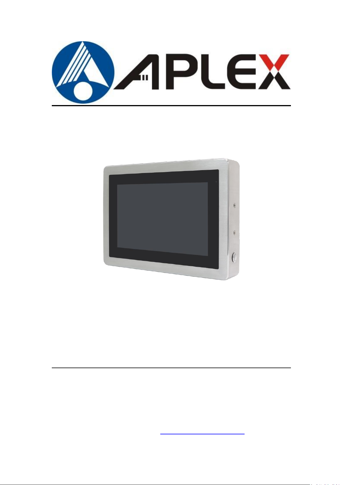
ViTAM-6XX Series
10.1”, 12.1”, 15”, and 21” New Gen. IP66/IP69K Stainless Steel Panel PC
User Manual
Release Date Revision
Oct. 2017 V1.5
®2017 Aplex Technology, Inc. All Rights Reserved. Published in Taiwan
Aplex Technology, Inc.
15F-1, No.186, Jian Yi Road, Zhonghe District, New Taipei City 235, Taiwan
Tel: 886-2-82262881 Fax: 886-2-82262883 URL: http://www.aplextec.com/zh/home.php
Page 3

1
Revision History
Reversion
Date
Description
0.1
2016/12/08
For Preliminary Release
0.2
2016/12/22
Update Power consumption and net weight Spec.
1.0
2017/01/11
Official Version
1.1
2017/06/02
Add 21 inch model
Modify optional function
Add micro SD card storage
1.2
2017/07/28
Add I/O drawing and definition
1.3
2017/10/13
Modify expansion I/O function
1.4
2018/11/01
Modify Operating Temperature
1.5
2018/11/07
Modify Operating system, remove QT and update
to Android 6.0.1 & Linux 4.1.15
ViTAM-6XX Series User Manual
Page 4

2
Electric Shock Hazard – Do not operate the machine with its back cover removed.
There are dangerous high voltages inside.
This equipment generates, uses and can radiate radio frequency energy and
if not installed and used in accordance with the instructions manual, it may cause
interference to radio communications. It has been tested and found to comply
with the limits for a Class A computing device pursuant to FCC Rules, which are
designed to provide reasonable protection against such interference when
operated in a commercial environment. Operation of this equipment in a
residential area is likely to cause interference in which case the user at his own
expense will be required to take whatever measures may be required to correct
the interference.
Warning!________________________
Caution
Risk of explosion if the battery is replaced with an incorrect type.
Batteries should be recycled where possible. Disposal of used batteries must be in
accordance with local environmental regulations.
Disclaimer
This information in this document is subject to change without notice. In no event
shall Aplex Technology Inc. be liable for damages of any kind, whether incidental or
consequential, arising from either the use or misuse of information in this
document or in any related materials.
ViTAM-6XX Series User Manual
Page 5

3
Accessories (as ticked) included in this package are:
□ Adaptor
□ Driver & manual CD disc
□ Other.___________________(please specify)
Packing List
ViTAM-6XX Series User Manual
Page 6

4
Safety Precautions
Follow the messages below to prevent your systems from damage:
◆ Avoid your system from static electricity on all occasions.
◆ Prevent electric shock. Don‘t touch any components of this card when
the card is power-on. Always disconnect power when the system is not
in use.
◆ Disconnect power when you change any hardware devices. For instance,
when you connect a jumper or install any cards, a surge of power may
damage the electronic components or the whole system.
ViTAM-6XX Series User Manual
Page 7

5
Table of Contents
Revision History…………………………………………………………………………………………………….1
Warning!/Caution/Disclaimer.................................................…………………………….…2
Packing List…………………………………….……………………………………………………………………..3
Safety Precautions…………………………………………………………………….…..……………………..4
Chapter 1 Getting Started
1.1 Features………………………..………………………...…………………………..6
1.2 Specifications…………………...………………………………………………….6
1.3 Dimensions………………………....…………………………………………….10
1.4 Brief Description of ViTAM-6XX Series………...……….……….……12
1.5 Yoke Mounting and VESA Mounting………………………...…………13
Chapter 2 Hardware
2.1 Motherboard Jumpers Setting and Connectors……...………....14
Chapter 3 Installations
3.1 Update Linux QT for SBC-7112.....................……….……………...20
3.2 Update Android Firmware............................……………………...24
Figures
Figure 1.1: Dimensions of ViTAM-610P/R/G(H)………………………………….10
Figure 1.2: Dimensions of ViTAM-612P/R/G(H)……..………..………………...10
Figure 1.3: Dimensions of ViTAM-615P/R/G(H)….….……..…………………..11
Figure 1.4: Dimensions of ViTAM-621P/R/G(H)….….……..…………………..11
Figure 1.5: Front View and Touch on/off Button of ViTAM-6XX Series..12
Figure 1.6: Rear View of ViTAM-6XX Series…..…….……………………...……12
Figure 1.7: Yoke Mounting of ViTAM-6XX Series…………...……………….….13
Figure 1.8: VESA Mounting of ViTAM-6XX Series...................................13
ViTAM-6XX Series User Manual
Page 8
6
Chapter 1 Getting Started
ViTAM-610
P/R/G/(H)
ViTAM-612
P/R/G/(H)
ViTAM-615
P/R/G/(H)
ViTAM-621
P/R/G/(H)
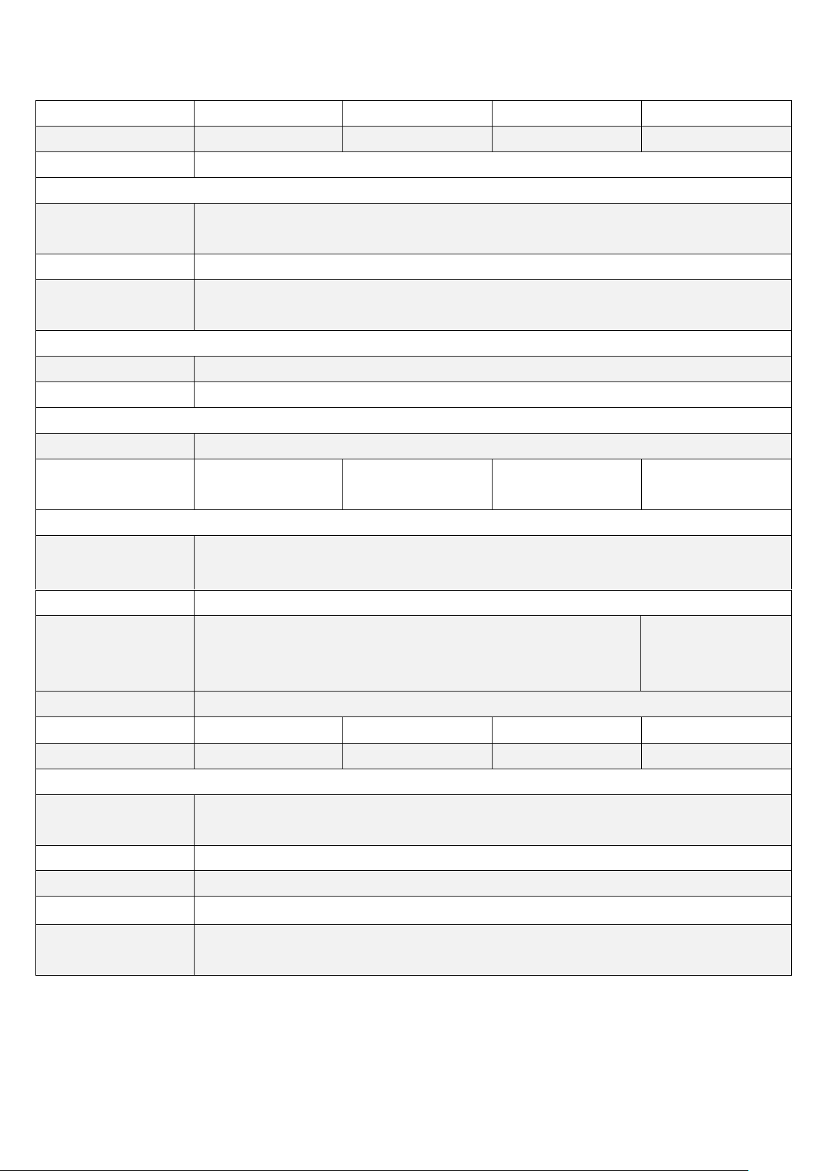
System
CPU
Freescale I.MX6 DualLite 1.0GHz
Chipset
SoC
Memory
Onboard 1GB DDR3 DRAM (2GB option)
RFID Module
RFID module design on the front side (option)
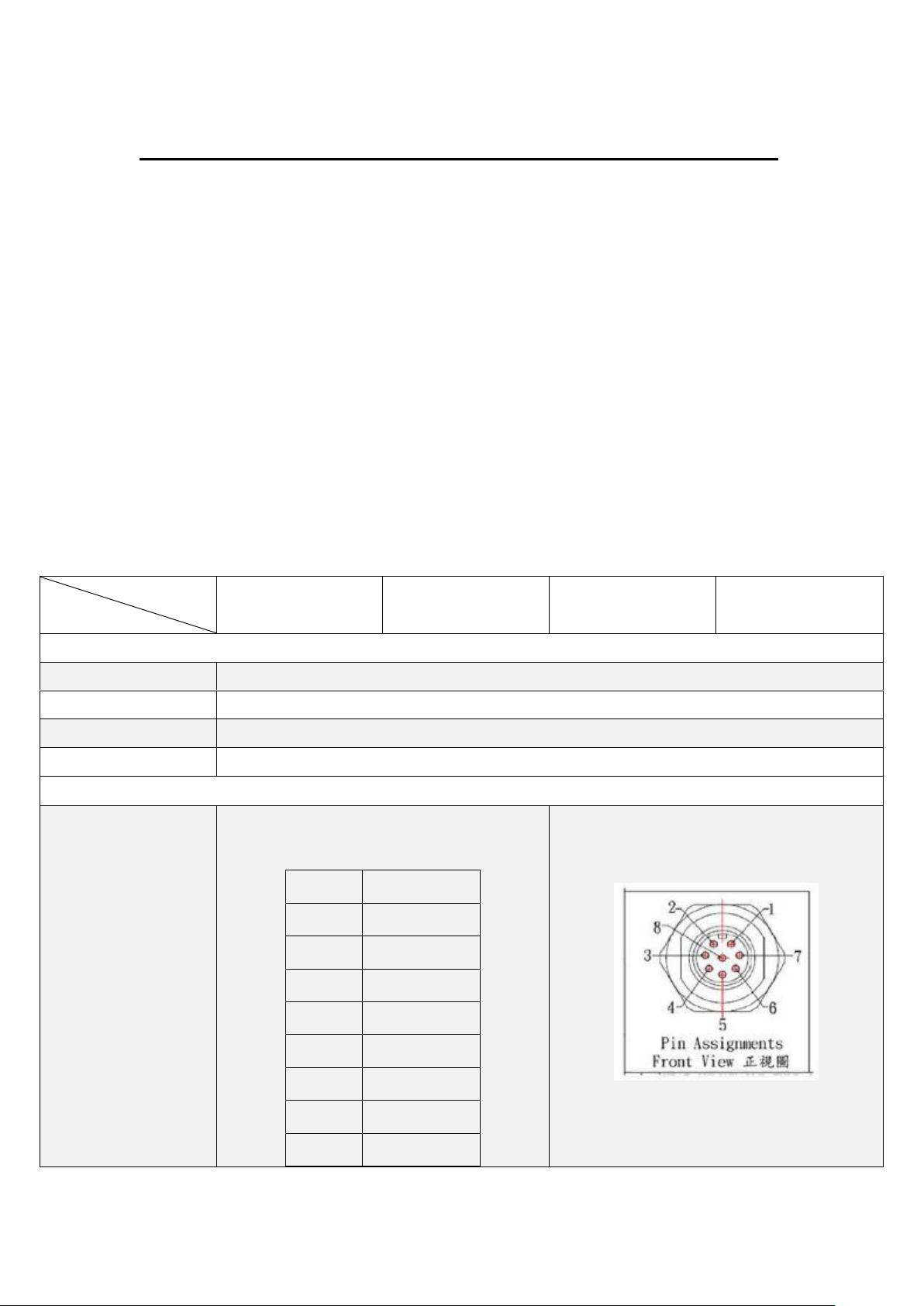
Outside IO Port – Standard M12 I/O Connector on the Rear Side
USB
1 x M12 for 2 x USB 2.0
USB1/2:
CN1
Pin Define
1
USB1 5V
3
D1-
4
D1+
7
GND
2
USB2 5V
5
D2- 6 D2+
8
GND
1.1 Features
10.1”, 12.1”, 15”, and 21” New generation stainless steel panel PC
Freescale I.MX6 DualLite 1.0GHz onboard processor
True flat front bezel design and grade 304 stainless steel enclosure (grade 316
for option)
IP66/IP69K rated with M12 connectors
Support resistive touch, projected capacitive touch, and glass
Touch on/off button on the side edge for hygienic cleaning
Support ergonomic versatile mounting: Yoke mounting / space-saving VESA
mounting.
1.2 Specifications
ViTAM-6XX Series User Manual
Page 9
7
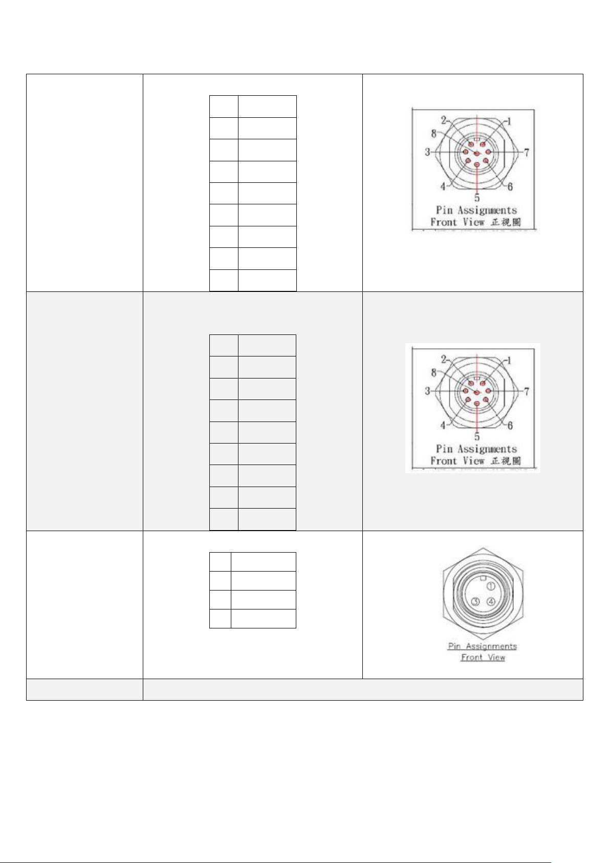
Serial/Parallel
1 x M12 for RS-232/422/485, Default RS-232
Pin Define
1
DCD 2 RXD
3
TXD
4
DTR 5 GND
6
DSR
7
RTS
8
CTS
LAN
1 x M12 for LAN
LAN:
Pin Define
2
LAN1_0+
1
LAN1_0-
4
LAN1_1+
3
LAN1_1-
6
LAN1_2+
5
LAN1_2-
8
LAN1_3+
7
LAN1_3-
Power
1 x DC power input (9~36V) by M12 connector
Pin Define
1
NC 3 VCC 4 GND
Others
1 x Touch on/off button on the side
ViTAM-6XX Series User Manual
Page 10
8
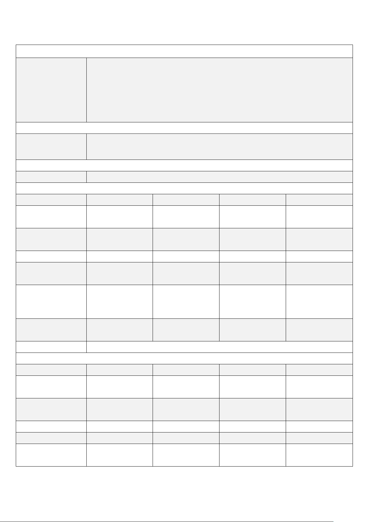
Outside IO Port – M12 I/O for option
Option
TB-508 Series :
1 x RS-232/422/485
1 x 8-bit GPIO
1 x CAN
1 x POE via AG5300
Storage Space
Storage
Onboard 4GB eMMC NAND flash
1 x Micro SD card slot on board
Expansion
Expansion Slot
1 x Mini PCIe slot for WIFI/BT (option)
Display
Display Type
10.1 TFT LCD
12.1” TFT LCD
15” TFT LCD
21.5” TFT LCD
Max. Resolution
1280 x 800
800 x 600
1024 x 768 (option)
1024 x 768
1920 x 1080
Max. Color
16.7M
262K / 16.2M
(option)
16.7M
16.7M
Luminance (cd/m2)
350
450 / 500 (option)
420
300
Contrast Ratio
800: 1
800: 1 / 700: 1
(option)
800: 1
3000:1
Viewing Angle
170(H) / 170(V)
160(H) / 150(V)
160(H) / 140(V)
(option)
160(H) / 160(V)
178(H) / 178(V)
Backlight Lifetime
15,000 hrs
50,000 hrs /
30,000 hrs (option)
50,000 hrs
50,000 hrs
Option
Optical bonding
Display – High Brightness LCD (option)
Display Type
10.1 TFT LCD
12.1” TFT LCD
15” TFT LCD
21.5” TFT LCD
Max. Resolution
1280 x 800
800 x 600
1024 x 768 (option)
1024 x 768
1920 x 1080
Max. Color
16.7M
262K / 16.2M
(option)
262K
16.7M
Luminance (cd/m2)
1000
1000
1000
1000
Contrast Ratio
800: 1
700: 1
800: 1
3000:1
Viewing Angle
170(H) / 170(V)
178H) / 178(V)
160(H) / 140(V)
160(H) / 150(V)
178(H) / 178(V)
ViTAM-6XX Series User Manual
Page 11
9
(option)
Backlight Lifetime
30,000 hrs
50,000 hrs
30,000 hrs
50,000 hrs
Option
Optical bonding
Touch Screen
Type
Resistive touch window (for R model)
Projected capacitive touch screen (for P model)
Interface
USB
Light Transmission
Resistive touch window: over 80%
Projected capacitive touch screen: over 90%
Glass Type
Type
AR
Light Transmission
Over 90%
Power
Power Input
DC 9~36V
Power Consumption
MAX: 13.6W (610R)
MAX: 10.3W (610P)
MAX: 11.1W (612R)
MAX: 12.4W (612P)
MAX: 11.8W (615R)
MAX: 12.1W (615P)
MAX: TBD (621R)
MAX: 22.5 (621P)
Mechanical
Color
304 Stainless steel enclosure (default)
316 Stainless steel enclosure (option)
Construction
Stainless steel enclosure
Mounting
VESA mount 75 x 75
Yoke mount
VESA mount 100 x
100
Yoke mount
IP Rating
IP66/IP69K
Dimension (mm)
300 x 220 x 53
335 x 265 x 53
399 x 324 x 53
571 x 362 x 55
Net Weight
3.8 Kg
4.6 Kg
7.1 Kg
9.8 kg
Environmental
Operating
temperature
0~50°C
0~40°C(For 21.5” High Brightness model)
Storage temperature
-30~70°C
Storage humidity
10 to 90% @ 40°C, non- condensing
Certification
CE / FCC Class A
Operating System
Support
Android 6.0.1
Linux 4.1.15
ViTAM-6XX Series User Manual
Page 12
10
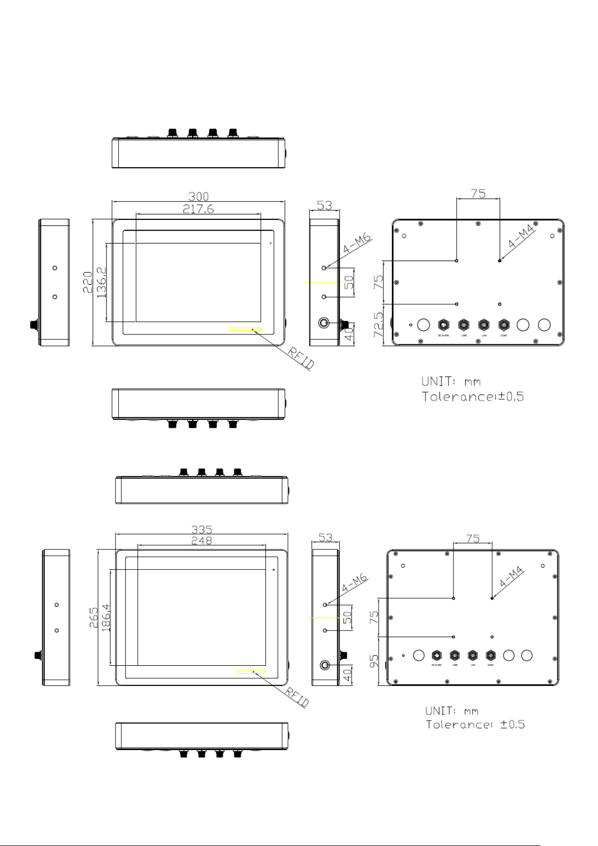
1.3 Dimensions
Figure 1.1: Dimensions of ViTAM-610P/R/G(H)
ViTAM-6XX Series User Manual
Page 13
11
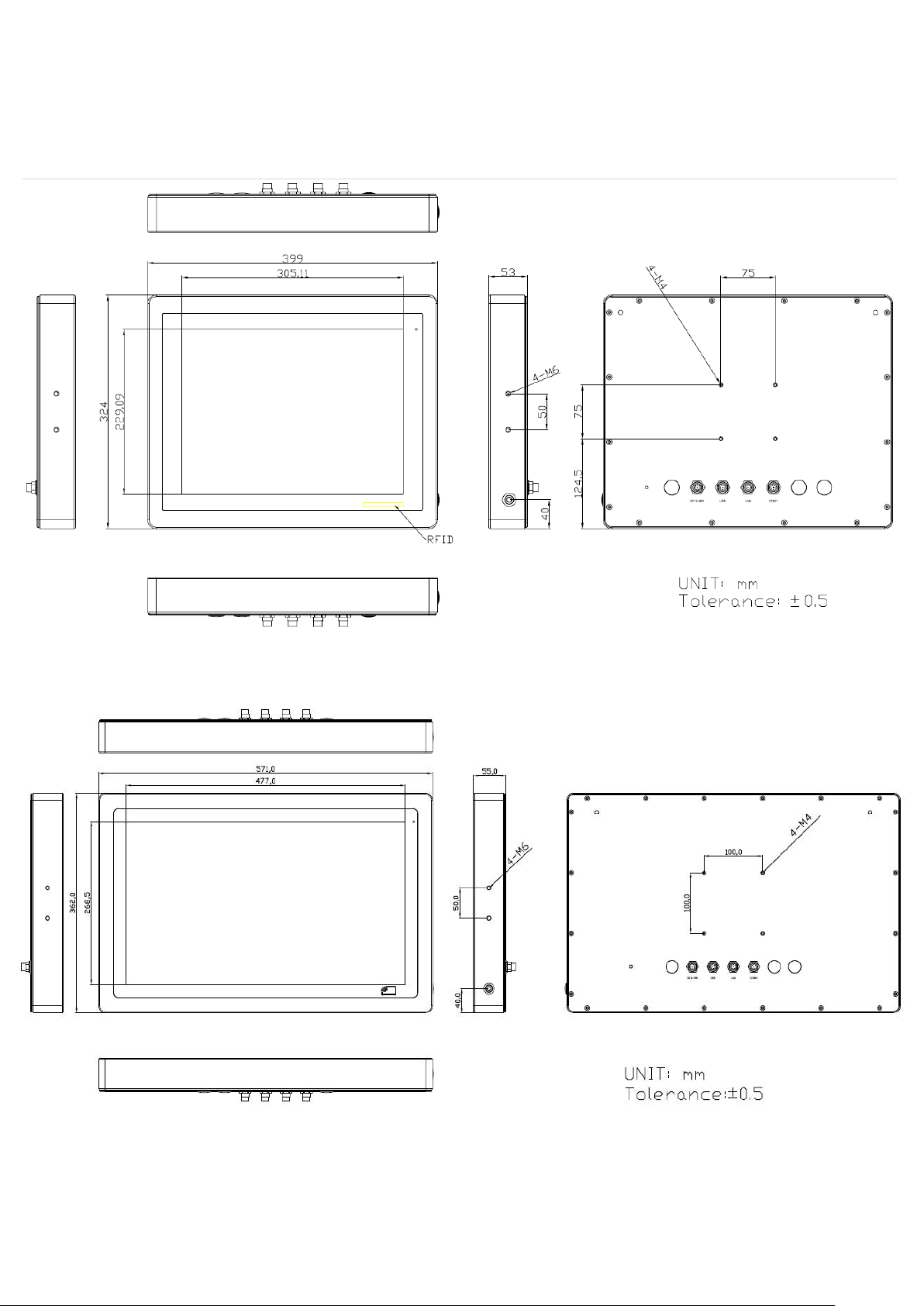
Figure 1.2: Dimensions of ViTAM-612P/R/G(H)
Figure 1.3: Dimensions of ViTAM-615P/R/G(H)
Figure 1.4: Dimensions of ViTAM-621P/R/G(H)
ViTAM-6XX Series User Manual
Page 14
12
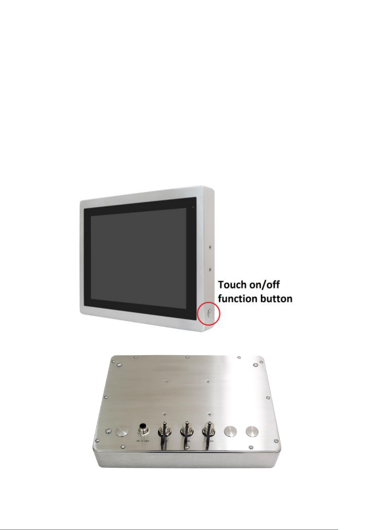
1.4 Brief Description of ViTAM-6XX Series
There are 10.1”, 12.1”, 15”, and 21.5” new generation stainless steel panel PC
in ViTAM-6XX series, which comes with true flat front bezel and fanless design. It
powered by Freescale I.MX6 DualLite 1.0GHz processor onboard, 1GB DDR3 DRAM,
and 4GB eMMC NAND flash for storage. ViTAM-6XX series is wide range DC 9~36V
power input and IP66/IP69K rated with M12 connectors. Furthermore, the models
support resistive touch, projected capacitive touch, and glass for option, and can be
high brightness LCD and optical bonding designed for option. It supports touch on/off
button on the side edge for hygienic cleaning and ergonomic versatile mounting:
Yoke mounting and space-saving VESA 75 x 75 (VESA 100 x 100 for 21.5”) mounting.
Figure 1.5 Front View and Touch on/off Button of ViTAM-6XX Series
Figure 1.6 Rear View of ViTAM-6XX Series
ViTAM-6XX Series User Manual
Page 15
13
1.5 Yoke Mounting and VESA Mounting
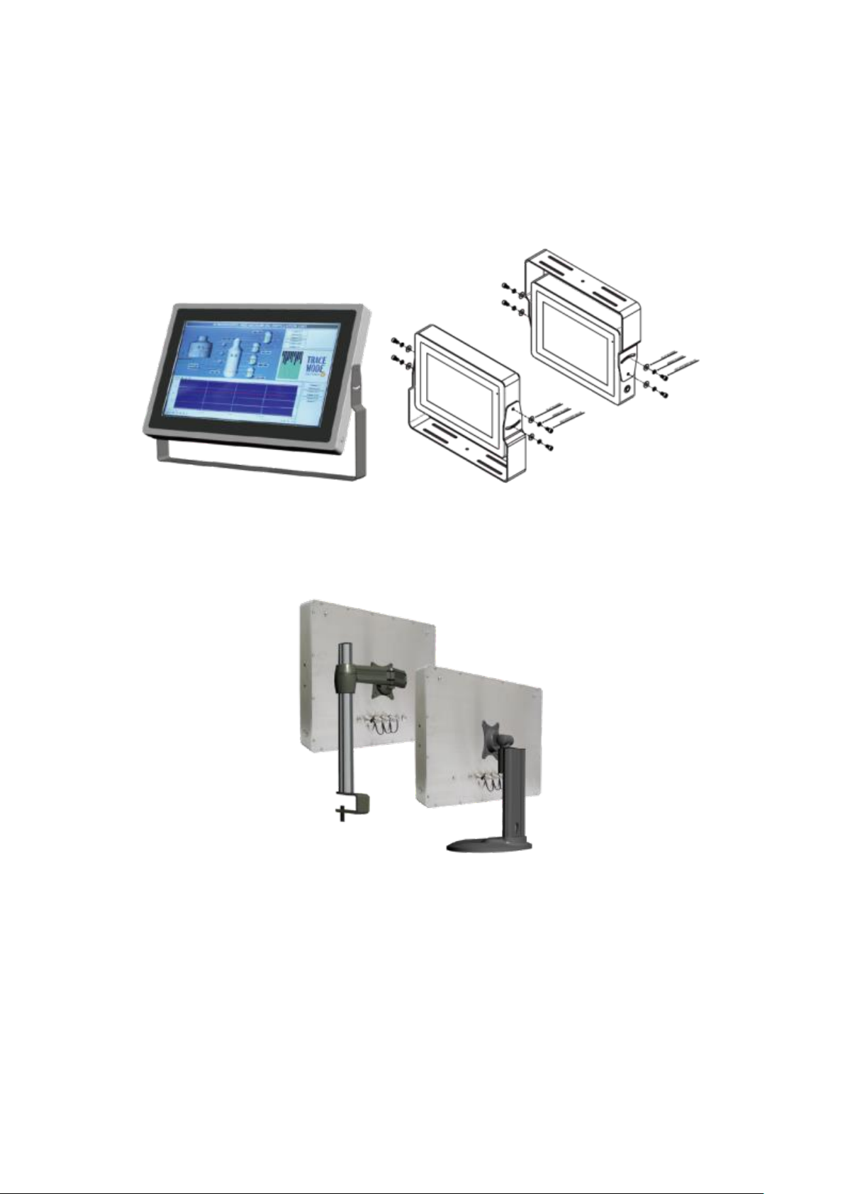
The ViTAM-6XX Series model can be Yoke mounted and VESA mounted as shown in
Picture below.
Figure 1.7: Yoke mounting of ViTAM-6XX Series
Figure 1.8: VESA mounting of ViTAM-6XX Series
ViTAM-6XX Series User Manual
Page 16

14
Chapter 2 Hardware
Signal Name
Pin#
Pin#
Signal Name
PWRON
1 2 GND
POR_B
3 4 GND
5V_S0
5 6 GND
GPIO_IN0
7 8 GPIO_IN1
GPIO_IN2
9
10
GPIO_IN3
GPIO_OUT0
11
12
GPIO_OUT1
GPIO_OUT2
13
14
GPIO_OUT3
I2C3_SCL
15
16
5V_S0
I2C3_SDA
17
18
NC
GND
19
20
NC
UART1_TXD_B
21
22
GND
UART1_RXD_B
23
24
UART2_TXD
NC
25
26
NC
NC
27
28
UART2_RXD
GND
29
30
NC
2.1 Motherboard Jumpers Setting and Connectors
1. J5:
(Micro USB OTG 5P Connector), it is used to download and connect to Android App.
2. USB1:
(Double stack USB type A), Front USB connector, it provides 2 USB2.0 ports,
High-speed USB 2.0 allows data transfers up to 480 Mb/s, support USB full-speed and
low-speed signaling.
3. LAN1:
(RJ45 Connector), Front LAN port. One standard 10/100M RJ45 Ethernet port is
provided. Used Atheros AR8031 chipset, support LINK LED (green) and ACTIVE LED
(yellow).
4. MIO1:
(1.25mm Pitch 2*15 Connector), Including eight General-purpose input/output、a
group of SMBUS and two groups of serial communication interfaces, it provides a
group of self-programming interfaces to customers for flexible use.
ViTAM-6XX Series User Manual
Page 17
15
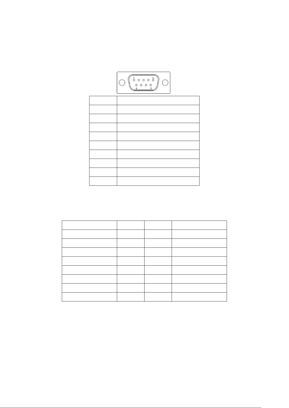
5. COM1
Pin#
Signal Name
1
DCD3-_422TX-_485-
2
RXD3_422TX+_485+
3
TXD3_422RX+
4
DTR3_422RX-
5
GND
6
NC 7 NC 8 NC 9 COM3_9PIN(connect to JP1)
Signal Name
Pin#
Pin#
Signal Name
5V_S0
1 2 NC
USBDN_CON2_DM3
3 4 UART4_TXD
USBDN_CON2_DP3
5 6 UART4_RXD
GND
7 8 GND
GND
9
10
CAN1_TX
I2C2_SDA
11
12
CAN1_RX
I2C2_SCL
13
14
NC
3P3V_S0
15
16
NC
(Type DB9), Front serial port, standard DB9 Male serial port is provided to make a
direct connection to serial devices. Used the SP339E as the driver, which is an
advanced multiprotocol transceiver supporting RS-232, RS-485 and RS-422.
6. CON2:
(2.0mm Pitch 2*8 Pin Socket), it provides a group USB2.0、SMBUS、UART and CANBUS
interfaces.
7.CON1:
(TF Card Socket), Support TF Card devices.
8. TOUCH1:
(2.00mm Pitch 2*5 Pin Header), Used the AR1021 as the touch screen controller
which supports resistive touch screen.
ViTAM-6XX Series User Manual
Page 18

16
Signal Name
Pin#
Pin#
Signal Name
Y-
1 2 SY-
SY+
3 4 Y+
X-
5 6 5WSX-
SX+
7 8 X+
M2(U17)
9
10
GND
Signal Name
Pin#
Pin#
Signal Name
VCC_LVDS0
1 2 VCC_LVDS0
GND
3 4 GND
LVDS0_TX0_N
5 6 LVDS0_TX0_P
LVDS0_TX1_N
7 8 LVDS0_TX1_P
LVDS0_TX2_N
9
10
LVDS0_TX2_P
NC
11
12
NC
LVDS0_CLK_N
13
14
LVDS0_CLK_P
GND
15
16
NC
BKLT_CTRL0
17
18
BKLT_EN_OUT0
VCC_BL0
19
20
VCC_BL0
Signal Name
Pin#
Pin#
Signal Name
VCC_LVDS1
1 2 VCC_LVDS1
GND
3 4 GND
LVDS1_TX0_N
5 6 LVDS1_TX0_P
LVDS1_TX1_N
7 8 LVDS1_TX1_P
LVDS1_TX2_N
9
10
LVDS1_TX2_P
LVDS1_TX3_N
11
12
LVDS1_TX3_P
LVDS1_CLK_N
13
14
LVDS1_CLK_P
9. SIM1:
(SIM Card Socket), Support SIM Card devices.
10. LVDS1:
(1.25mm Pitch 2*10 Connector, DF13-20DP-1.25V), For 18-bit LVDS1 output
connector.
11. LVDS2:
(1.25mm Pitch 2*10 Connector, DF13-20DP-1.25V), For 18/24-bit LVDS1 output
connector.
ViTAM-6XX Series User Manual
Page 19
17
GND
15
16
NC
BKLT_CTRL1
17
18
BKLT_EN_OUT1
VCC_BL1
19
20
VCC_BL1
Pin#
Signal Name
1
VCC_BL0
2
VCC_BL0
3
GND
4
GND
5
BKLT_EN_OUT0
6
BKLT_CTRL0
Pin#
Signal Name
1
VRTC
2
GND
Pin#
Signal Name
1
VCC_BL1
2
VCC_BL1
3
GND
4
GND
5
BKLT_EN_OUT1
6
BKLT_CTRL1
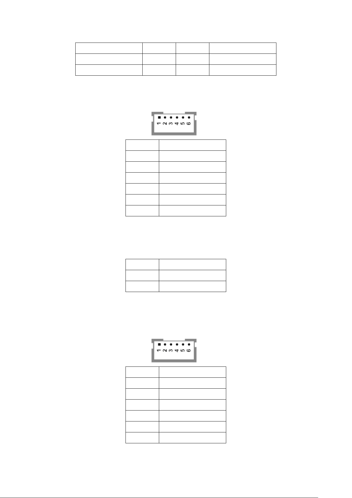
12. INVT1:
(2.0mm Pitch 1*6 box Pin Header), Backlight control connector for LVDS1.
13. BT1:
(1.0mm Pitch 1*2 box Pin Header), 3.0V Li battery is embedded to provide power for
RTC.
14. INVT2:
(2.0mm Pitch 1*6 box Pin Header), Backlight control connector for LVDS2.
ViTAM-6XX Series User Manual
Page 20

18
15. J20:
JP1 Pin#
Function
Close 1-2
COM1 Pin9 = NC (option)
Close 3-4
COM1 Pin9 = +5V (default)
Close 5-6
COM1 Pin9 = +12V (option)
J1 Pin#
Function
Close 1-2
VCC_LVDS0 = 3.3V (option)
Close 2-3
VCC_LVDS0 = 5V (default)
J2 Pin#
Function
Close 1-2
VCC_ BL0 = 5V (option)
Close 2-3
VCC_ BL0 = 12V (default)
J3 Pin#
Function
Close 1-2
VCC_LVDS1 = 3.3V (option)
Close 2-3
VCC_LVDS1 = 5V (default)
(1.0mm Pitch 1*2 box Pin Header), Reserved to connect switch reset button..
16. MPCIE1:
(Mini PCIe Socket 52Pin), mini PCIe socket, it is located at the top, it supports mini
PCIe devices with USB2.0 and SIM and SMBUS and PCIe signal. MPCIe card size is
30*30mm or 30*50.95mm.
17. JP1:
(2.0mm Pitch 2*3 Pin Header), COM1 jumper setting, pin1~6 are used to select signal
out of pin 9 of COM1 port.
18. J1:
(2.0mm Pitch 1*3 Pin Header), LVDS1 jumper setting. It is used to provide 3.3V or 5V
voltage to VCC_LVDS0.
19. J2:
(2.0mm Pitch 1*3 Pin Header), LVDS1 jumper setting. It is used to provide 5V or 12V
voltage to VCC_BL0.
20. J3:
(2.0mm Pitch 1*3 Pin Header), LVDS2 jumper setting. It is used to provide 3.3V or 5V
voltage to VCC_LVDS1.
ViTAM-6XX Series User Manual
Page 21

19
21. J4:
J4 Pin#
Function
Close 1-2
VCC_ BL1 = 5V (option)
Close 2-3
VCC_ BL1 = 12V (default)
SW2 Pin#
Function
Function
1-4
Close
Open(default)
BKLT_CTRL0 = 3.3V
BKLT_CTRL0 = 5V
2-3
Close
Open(default)
BKLT_EN_OUT0 = 3.3V
BKLT_EN_OUT0 = 5V
SW3 Pin#
Function
Function
1-4
Close
Open(default)
BKLT_CTRL0 = 3.3V
BKLT_CTRL0 = 5V
2-3
Close
Open(default)
BKLT_EN_OUT0 = 3.3V
BKLT_EN_OUT0 = 5V
(2.0mm Pitch 1*3 Pin Header), LVDS2 jumper setting. It is used to provide 5V or 12V
voltage to VCC_BL1.
22. SW2:
Dial Switch, it is used to select the voltage for BKLT_CTRL0 and BKLT_EN_OUT0.
23. SW3:
Dial Switch, it is used to select the voltage for BKLT_CTRL1 and BKLT_EN_OUT1.
ViTAM-6XX Series User Manual
Page 22
20
Chapter 3 Installations
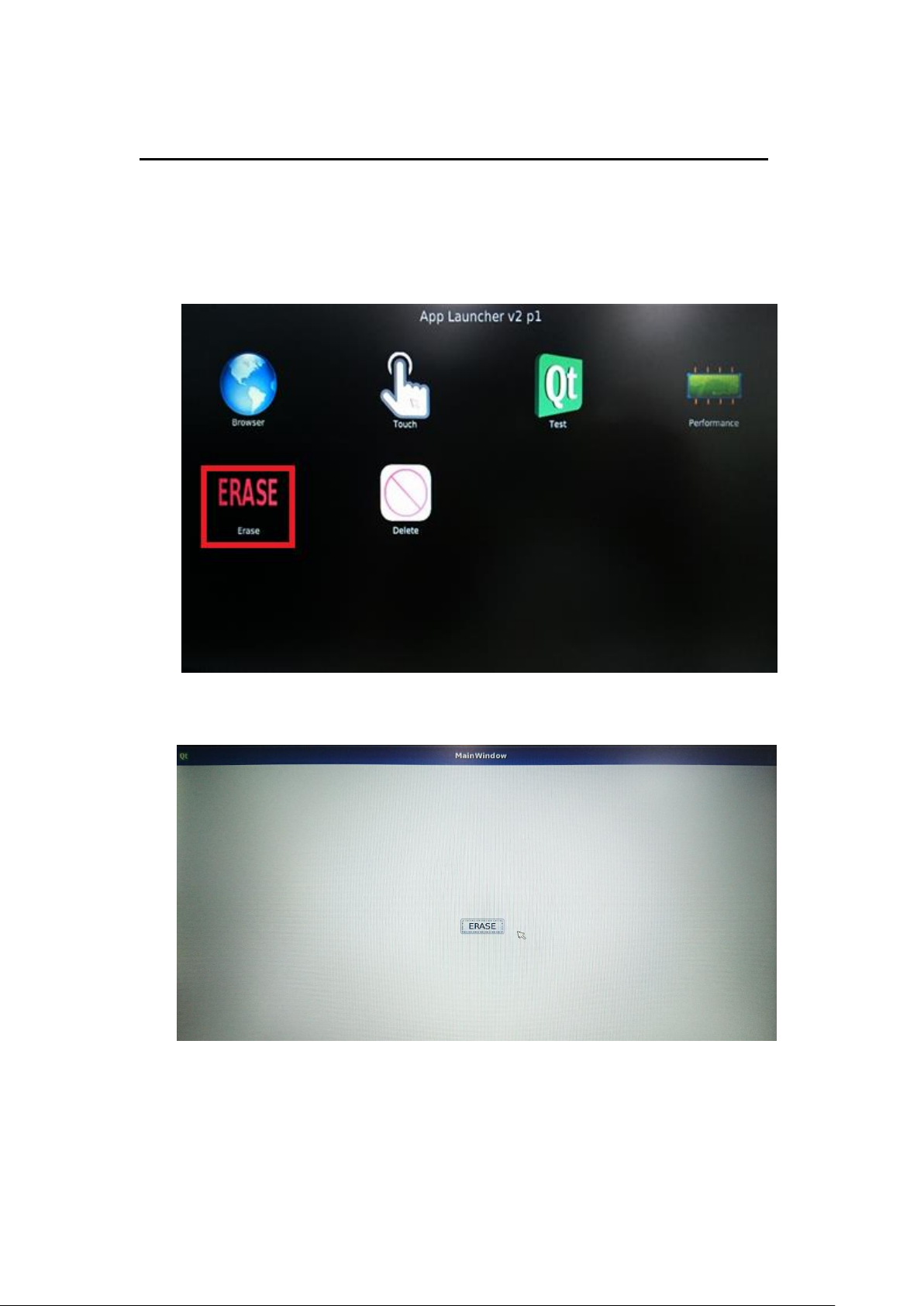
3.1 Update Linux QT for SBC-7112
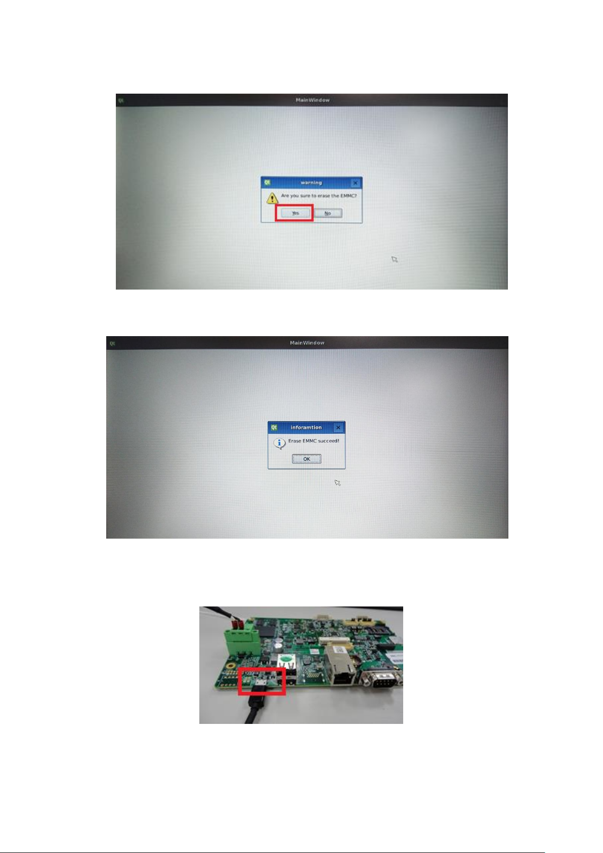
1. Select the “ERASE” APP on desktop to clear EMMC data(change to Download
Mode)
ViTAM-6XX Series User Manual
Page 23
21
2. Click “Yes” to erase the EMMC.
3. Reset machine when see the message “Erase EMMC success!!”
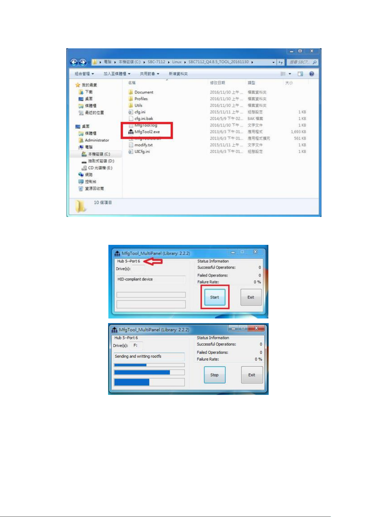
4. Connect Micro USB Cable from SBC-7112 to your desktop/laptop and run update
tool “MftTool2.exe”.
ViTAM-6XX Series User Manual
Page 24
22
5. It will show up “Hub X--Port Y” on the upper left side if USB cable has been
connected well, and then click “Start” to update Linux QT
ViTAM-6XX Series User Manual
Page 25
23
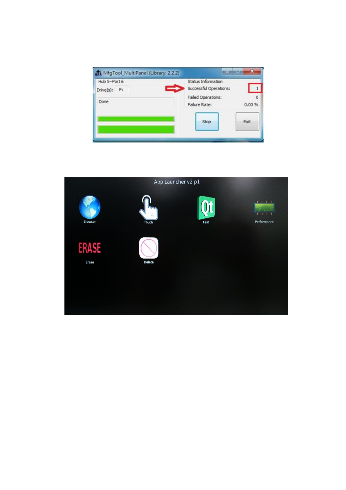
6. When you finish updating, the screen will show the increasing counting numbers
of “Successful Operations”. Click “Stop” and “Exit” then reset machine.
7. Linux QT has been updated successfully!!
ViTAM-6XX Series User Manual
Page 26
24
3.2 Update Android Firmware
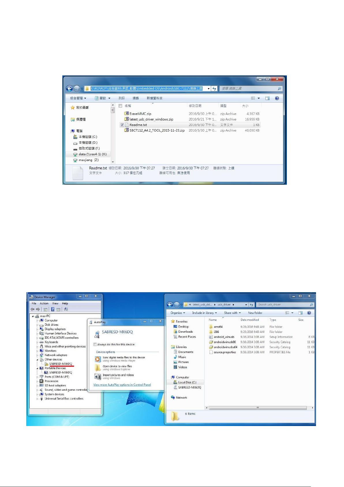
To update Android firmware, there must be three files as shown below.
1. File1: latest_usb_driver_windows.zip (ADB Interface Driver)
The USB driver should be connected to ARMPAC device
2. File2: EraseMMC.zip
Erase all data on Flash and switch to download mode before updating
Android firmware.
3. File3: SBC7112_A4.2_TOOL_2015-11-23.zip
Update Android Firmware & update utility
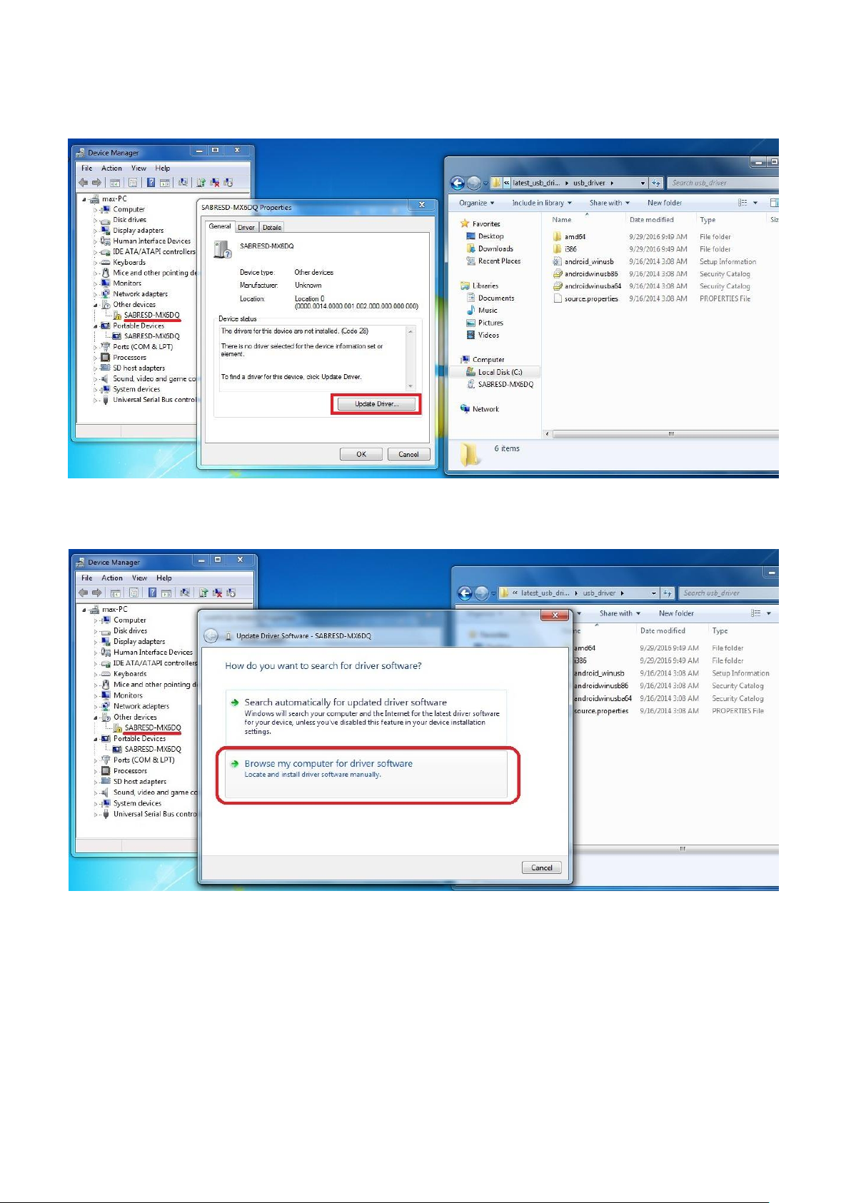
Step 1. File1: latest_usb_driver_windows.zip (ADB Interface Driver)
1) Install ADB Interface Driver(laster_usb_driver_windows.zip).
ViTAM-6XX Series User Manual
Page 27
25
2) Click “Update Driver...” to continue.
3) Select “Browse my computer for driver software” to locate and install driver software.
ViTAM-6XX Series User Manual
Page 28
26
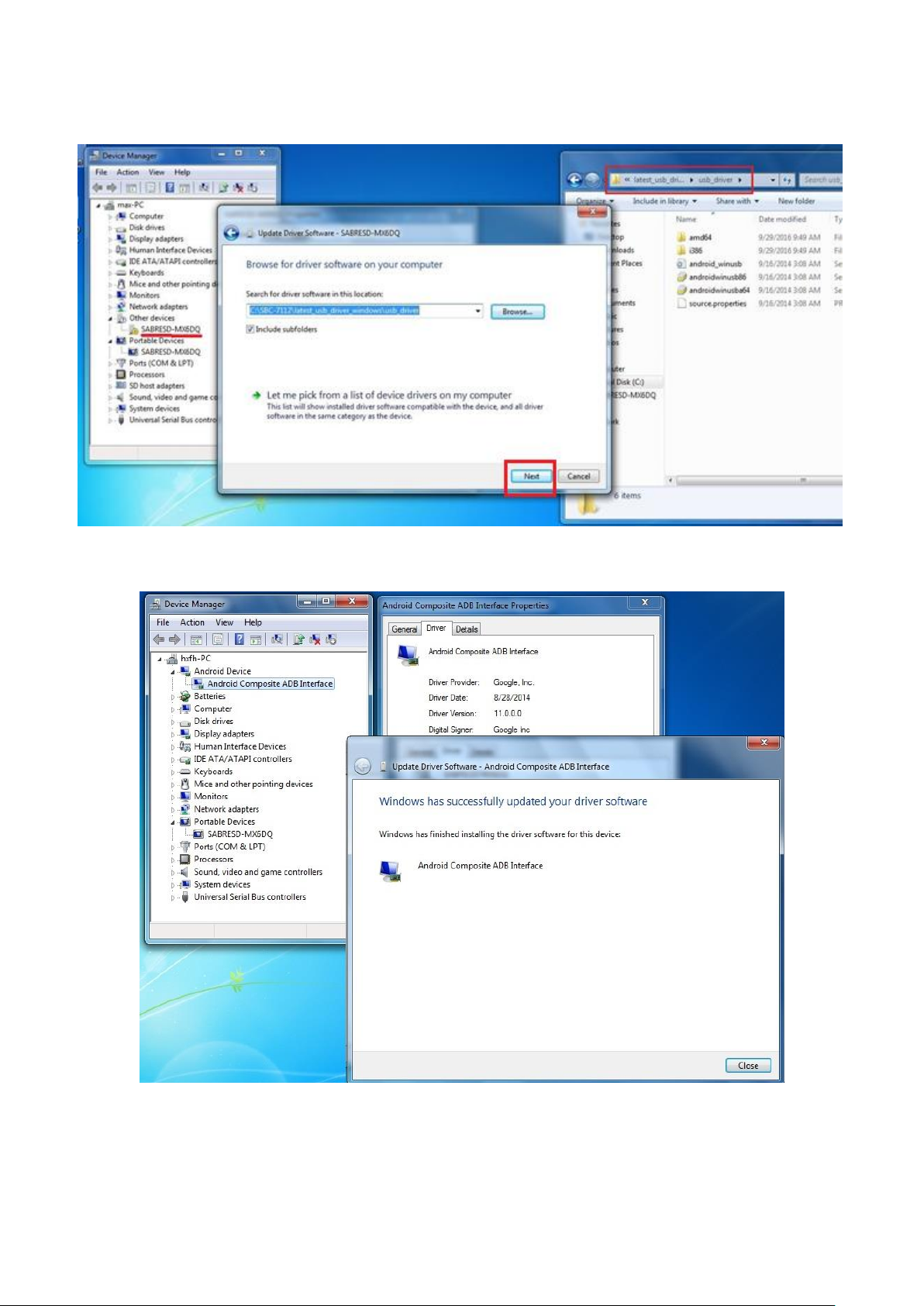
4) Click “Next” to continue.
5) Click “Close” to complete the driver installation.
ViTAM-6XX Series User Manual
Page 29
27
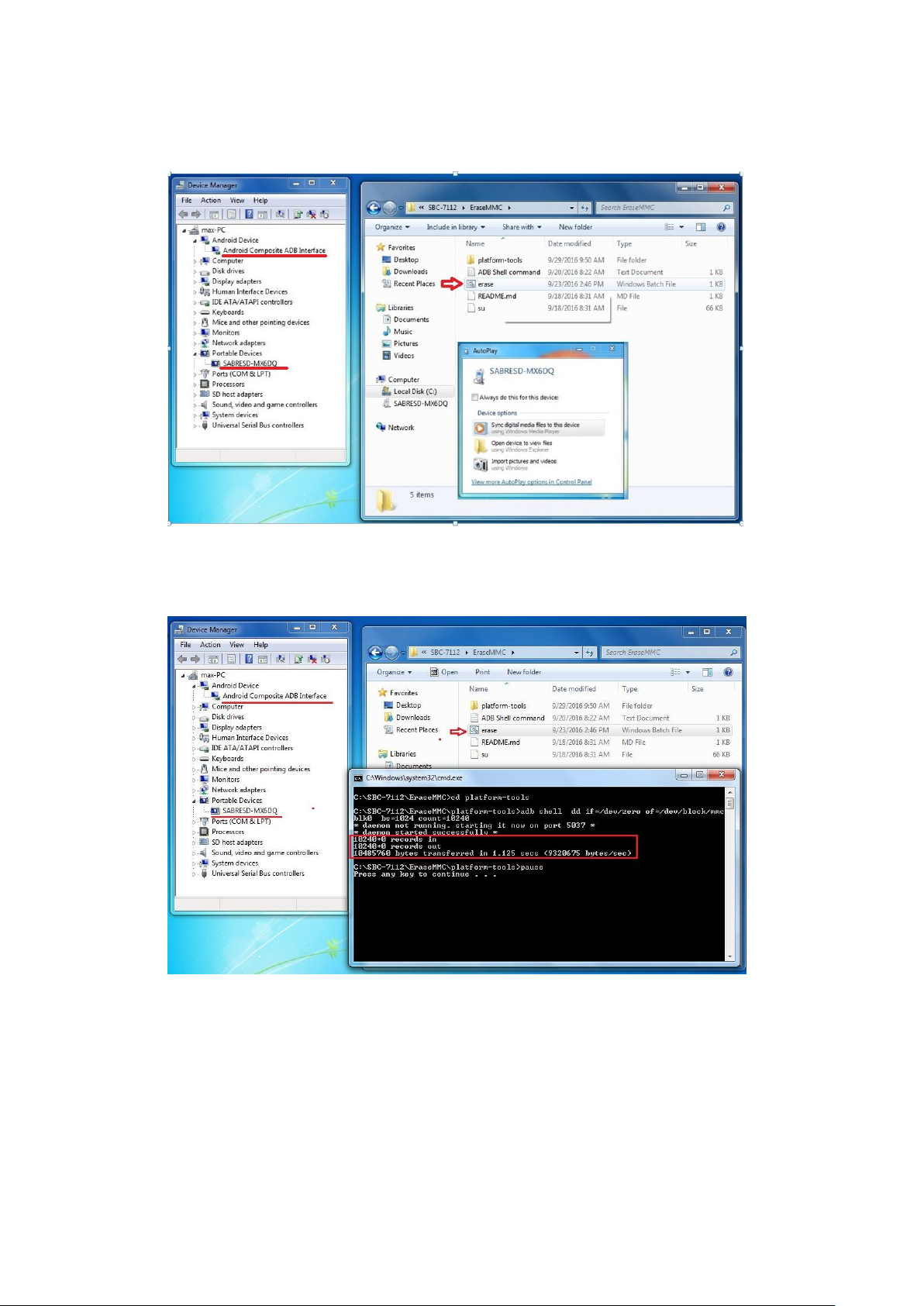
Step 2. File2: EraseMMC.zip
1) Switch to Download mode (Erase all data on Flash) via “ERASE.bat”.
2) It switches to Download Mode when the screen shows like the picture below,
and then you can reset the ARMPAC.
ViTAM-6XX Series User Manual
Page 30
28
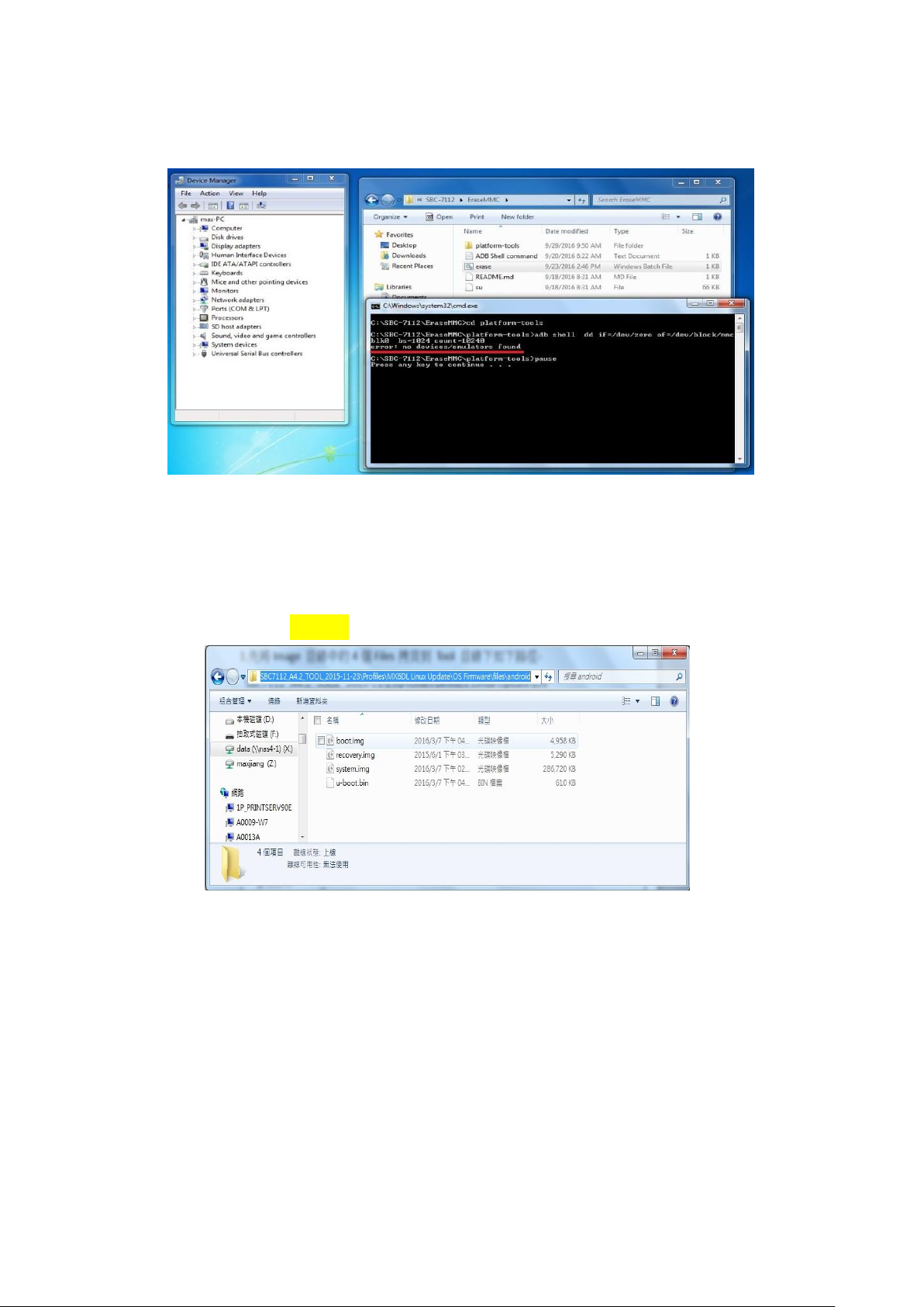
There will be error message as shown like below picture if the USB hasn’t been
connected well.
Step 3. File3: SBC7112_A4.2_TOOL_2015-11-23.zip
1) Copy all images files include boot.img & recovery.img & system.img & u-boot.bin
into “android” folder as below.
SBC7112_A4.2_TOOL_2015-11-23\Profiles\MX6DL Linux Update\OS
Firmware\files\android
ViTAM-6XX Series User Manual
Page 31
29
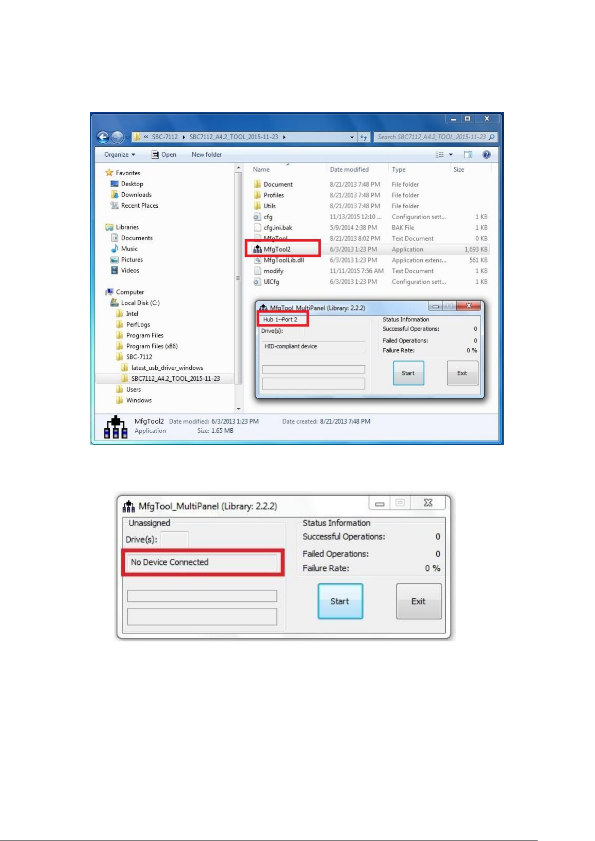
2) Run “MftTool2.exe” to update firmware utility. The screen will show “HUB X-Port
X” if the USB has been connected well. Then click “Start” to update firmware.
The screen will show like this picture if the USB has not been connected well.
ViTAM-6XX Series User Manual
Page 32
30
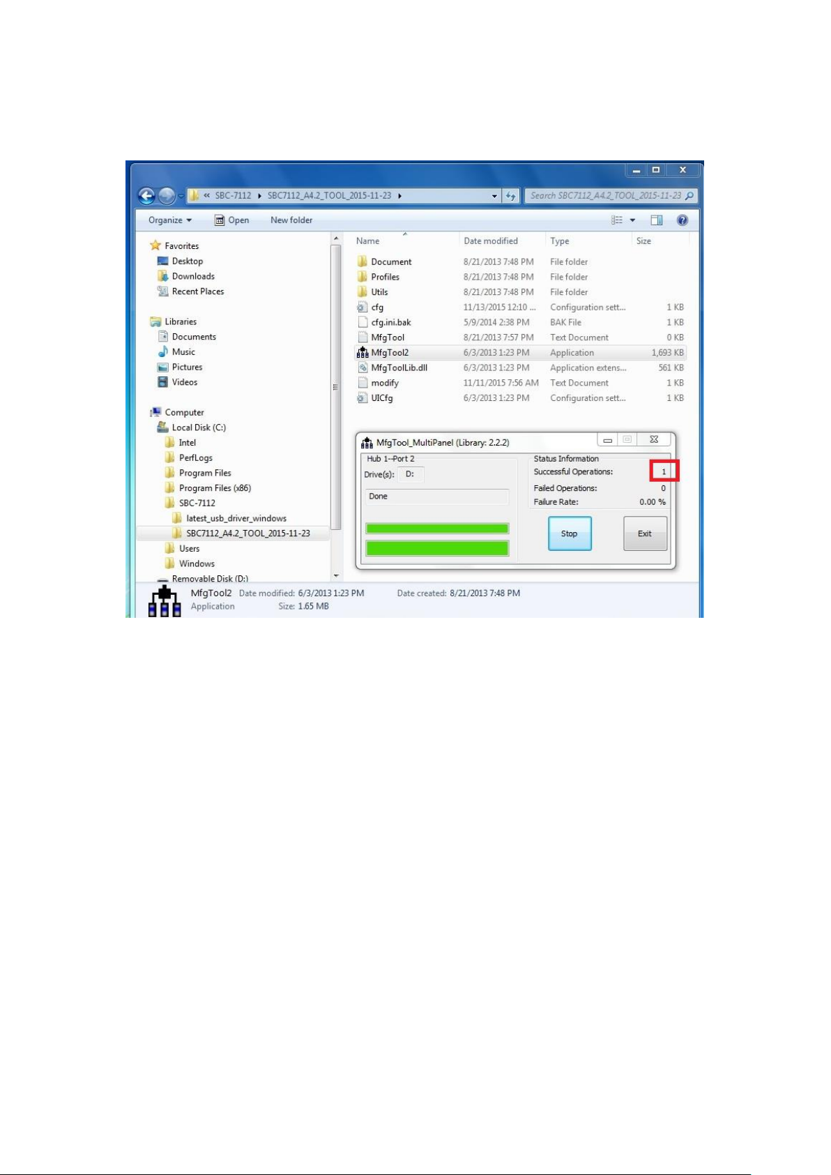
3) The screen will show the increasing counting numbers of “Successful Operations”
when firmware has been updated successfully.
ViTAM-6XX Series User Manual
 Loading...