

Aplex ACS-2645 User Manual

1
ACS-2645 Box PC
User Manual
Release Date Revision
Aug, 2014 V1.2
® 2014 Aplex Technology, Inc. All Rights Reserved. Published in Taiwan
Aplex Technology, Inc.
15F-1, No.186, Jian Yi Road, Zhonghe District, New Taipei City 235, Taiwan
Tel: 886-2-82262881 Fax: 886-2-82262883 E-mail: aplex@aplex.com.tw URL: www.aplex.com.tw
ACS-2645 User Manual

2
Warning!_______________________________
This equipment generates, uses and can radiate radio frequency energy and if not installed and
used in accordance with the instructions manual, it may cause interference to radio
communications.
It has been tested and found to comply with the limits for a Class A computing device pursuant to
FCC Rules, which are designed to provide reasonable protection against such interference when
operated in a commercial environment. Operation of this equipment in a residential area is likely
to cause interference in which case the user at his own expense will be required to take whatever
measures may be required to correct the interference.
Electric Shock Hazard – Do not operate the machine with its back cover removed. There are
dangerous high voltages inside.
ACS-2645 User Manual

3
Packing List
Accessories (as ticked) included in this package are:
□ AC power cable
□ Driver & manual CD disc
□ Other.___________________(please specify)
Safety Precautions
Follow the messages below to avoid your systems from damage:
◆ Avoid your system from static electricity on all occasions.
◆ Prevent electric shock. Don‘t touch any components of this card when the card is
power-on. Always disconnect power when the system is not in use.
◆ Disconnect power when you change any hardware devices. For instance, when you
connect a jumper or install any cards, a surge of power may damage the electronic
components or the whole system.
ACS-2645 User Manual

4
Table of Contents______________________
Warning!……………………………………….…………………………………….……..….2
Packing List...................................................................................................................3
Safety Precautions........................................................................................................3
Chapter 1 Getting Started
1.1 Specifications………………………………………….………….……...…..6
1.2 Dimensions…………………………………...……………….…………......7
1.3 Brief Description ……………….……..…….……………….………………9
1.4 Installation of HDD................................................................................10
1.5 Installation of PCI Add-on.....................................................................12
Chapter 2 Hardware Installation
2.1 Mainboard Specifications…………………..……..…………….…………13
2.2 Board Dimensions………………………….…………...…….……………16
2.3 Jumpers and Connectors Location………..…………………………......17
2.4 Jumpers Setting and Connectors…………………………………….......19
Chapter 3 BIOS Setup
3.1 Operations after POST Screen.............................................................34
3.2 BIOS Setup Utility……..........................................................................35
3.3 Main Settings........................................................................................36
3.4 Advanced Settings................................................................................37
3.5 Chipset Settings................................................................................... 42
3.6 Boot Settings........................................................................................46
3.7 Security Settings...................................................................................48
3.8 Save & Exit Settings.............................................................................49
3.9 Examples of GPIO Programming…………………………………………51
Chapter 4 Installation of Drivers
4.1 Intel Chipset Driver.…………………………...………….…...……………59
4.2 Intel VGA Chipset Driver..…....…......……..………………………….......62
4.3 Intel Network Adapter Driver……..........................................................65
ACS-2645 User Manual

5
4.4 Realtek Audio Driver Installation………………………………….….……68
Figures
Figure 1.1: Dimensions of ACS-2645 ……………..…………………………...7
Figure 1.2: Front View of ACS-2645…………….………………………….......9
Figure 1.3: Rear View of ACS-2645………………….………………………....9
Figure 2.1: Mainboard Dimensions……………………………………………16
Figure 2.2: Jumpers and Connectors Location-TOP…………………...……17
Figure 2.3: Jumpers and Connectors Location- Bottom………………….…18
ACS-2645 User Manual

6
Chapter 1________________Getting Started
Specs
ACS-2645
CPU
Intel Atom Processor D2550 1.86GHz , L2 Cache 1MB
System Chipset
Intel NM10 Express
System Memory
Support 2 x SO-DIMM 204pin, up to 4GB DDRIII 800/1066MHz FSB
External I/O Port
Rear I/O Side
1 x RS-232 (COM1)
1 x RS-232 (COM2)
1 x DB15 VGA
4 x USB 2.0 Ports
2 x Ethernet RJ45 LAN Port
1 x 9~32V DC Power input
1 x Audio Ports (MIC-in, Line out)
1 x 2 Pin Power Switch (terminal block)
2 x LED Indication (Power/HDD)
1 x HDMI
1 x Power button switch
1 x CF Slot by USB
1 x COM RS-422/485 (COM3, default:RS-485)
1 x COM RS-232 (COM4)
1 x 10 pins terminal block for 1 Ground/VCC/ 4 in & out DIDO
Expansion Slots
Default: 1 x PCI and PCIe x1 slots
Option: 2 x PCI slots
Storage
Default 2 x 2.5” SATA HDD space
1 x External CF slot
Power Supply
On board DC 9~32V / AC power input
Construction / Color
Black Steel and Aluminum Heatsink as ACS-2695
Mounting
Default: Wall mount / Option: Din Rail mount (single or dual)
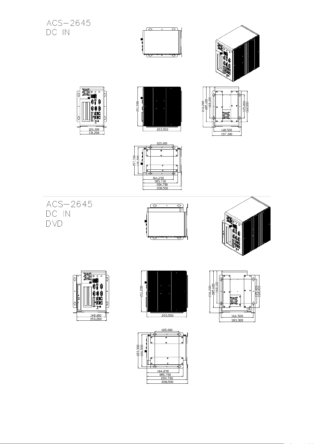
Dimensions(WxHxD)
211.2(W) x 203.5(H) x 131.2(D)
211.2(W) x 203.5(H) x 157.3(D)
(with DVD Device)
Gross Weight
5kgs
Operating Temperature
0~50 °C
Storage Temperature
-20~60 °C
Storage Humidity
10%~90%@ 40°C, non-condensing
Certificate
CE / FCC Class A
1.1 Specifications
ACS-2645 User Manual

7
1.2 Dimensions
ACS-2645 User Manual
8
ACS-2645 User Manual
Figure 1.1: Dimensions of ACS-2645
9
1.3 Brief Description of ACS-2645
ACS-2645 is a fan design High-efficiency Thermal Solution Box PC, powered by Intel Atom Processor
D2550 1.86GHz and supporting 2 x SO-DIMM 204pin, up to 4GB DDRIII 800/1066MHz FSB, 4 x USB
connector, 4 x COM Ports, support 2 x SATA HDD space, 1 x external CF slot, 1 x PCI and 1 x PCIe x
16 slot expansion, DC Power 9~32V input etc. It is ideal for Industrial Automation, Factory Automation,
Machine Vision, Process Control, Data Terminal, TI, Surveillance, etc. and running factory operations
from small visual interface and maintenance applications to large control process applications.
ACS-2645 works very well along with any of our Display series and it absolutely can provide an easy
way to perform control and field maintenance.
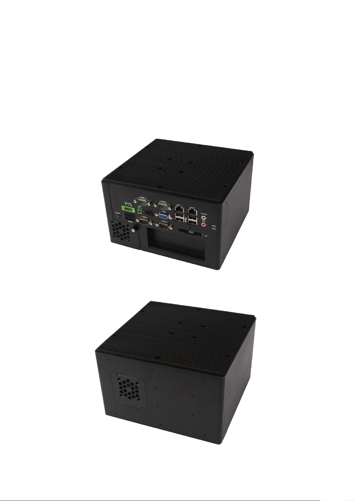
Figure 1.2: Front View of ACS-2645
ACS-2645 User Manual
Figure 1.3: Rear View of ACS-2645

10
1.4 Installation of HDD
Step 1
There is one screw which connects to the
chassis. Pull out the chassis towards the I/O
side after unscrewing as shown in the
picture.
Step 2
There is 1 screw to deal with when
enclosing or removing the HDD bracket .
Loosen screws and draw the HDD bracket
out.
Loosen 4 screws
ACS-2645 User Manual

11
Then you can replace HDD.
Step 3
Tighten the 1 screw as shown in the picture.
That’s how it should look after it has been
installed.
ACS-2645 User Manual

12
1.5 Installation of PCI Add-on
Step 1
There is one screw which connects to the
chassis. Pull out the chassis towards the I/O
side after unscrewing as shown in the
reference picture.
Step 2
Now slide the add on into the PCI slot,
making sure the golden part faces the slot.
When the part that is interfaced together
come into the right contact, slightly push the
add on into the rail of the slot.
After sliding the add on into the PCI
expansion slot, get the one screw as circled
tightened to finish the connection.
** Half Expansion-card limit to be not more
than 175mm length
Step 3
Tighten the 1 screw as shown in the picture.
That’s how it should look after it has been
installed.
ACS-2645 User Manual
13
Chapter 2__________Hardware Installation
Specifications
Board Size
170mm x 170mm
CPU Support
Intel Atom D2550 /1.86GHz (2cores,10W, onboard)
Intel Atom N2800 /1.86GHz (2cores,6.5W, option)
Intel Atom N2600 /1.60GHz (2cores,3.5W, option)
Chipset
Intel NM10 Express
Memory Support
2 x SO-DIMM (204pins)
D2550:up to 4GB DDRIII 800/1066MHz FSB
N2800:up to 4GB DDRIII 1066MHz FSB
N2600:up to 2GB DDRIII 800MHz FSB
Graphics
Integrated Intel GMA 3650 (D2550/N2800)
Integrated Intel GMA 3600 (N2600)
Display Mode
1 x CRT Port (VGA or VGA_PH)
1 x HDMI Port
1 x LVDS1 (18/24-bit single LVDS, option)
1 x LVDS2 (24-bit dual LVDS, option)
Support
Resolution
Up to 1920 x 1200 for CRT
Up to 1920 x1200 for HDMI
Up to 1440 x 900 for LVDS1 (D2550)
Up to 1366 x 768 for LVDS1 (N2600/N2800)
Up to 1920 x 1200 for LVDS2 (D2550)
Up to 1600 x 1200 for LVDS2 (N2600/N2800)
Dual Display
CRT+LVDS1
CRT+LVDS2
2.1 Mainboard specifications
Introduction
ASB-M7101 is a Mini-ITX industrial motherboard developed on the basis of Intel D2550 and NM10, which
provides abundant peripheral interfaces to meet the needs of different customers. Also, it features dual
1000M LAN port, 6-COM port and one Mini PCIE configuration. To satisfy the special needs of high-end
customers, PC104+ socket (capable of adjusting IO voltage) richer extension functions. The product is
widely used in various sectors of industrial control.
Specifications
ACS-2645 User Manual

14
CRT+HDMI
LVDS1+HDMI
LVDS2+HDMI
Super I/O
Winbond W83627UHG
BIOS
AMIBIOS
Storage
2 x SATA Connector
1 x Compact Flash II Slot for TB-522 or TB-523 (option)
Ethernet
2 x PCIe Gbe LAN by Intel 82583V
USB
4 x USB 2.0 stack ports for external
3 x USB 2.0 box Pin header for MIO1
1 x USB 2.0 internal for mini PCIe
Serial
1 x RS232/422/485 port, DB9 connector for external (COM1)
pin 9 w/5V/12V/Ring select
1 x RS232 port, DB9 connector for external (COM2)
pin 9 w/5V/12V/Ring select
1 x RS232 header for internal (COM5)
1 x RS232 header for internal (COM6),pin 10 w/5V/12V select
I/O Card TB-522/TB-523:
1 x 422/485 select header for internal MIO1 (COM3)
1 x RS232 header for internal MIO1 (COM4)
Digital I/O
8-bit digital I/O by Pin header for MIO2
4-bit digital Input
4-bit digital Output
Battery
Support CR2477 Li battery by 2-pin header
Audio
Support Audio via Realtek ALC662 HD audio codec
Support Line-out, MIC by JACK
Support Line-in, Line-out, MIC by 2x6-pin header
Keyboard /Mouse
PS2 K/B and Mouse by MIO2
1 x PS/2 keyboard
1 x PS/2 mouse
Expansion Bus
1 x PC 104+ connector (PCI master 4, jumper for +3.3V & 5V select)
2 x PCI-express 1X extend by 4x10 pin socket (PCIe1 option)
1 x mini-PCI-express slot (PCIe1 option:MPCIE or PCIE1X)
1 x CRT 2x6 Pin Header
Power
Management
1 x 3-pin power input connector (Wide range DC+9V~32V)
DC12V output by 2x2 pin Connectors
Switches and
Power on/off switch by TB-522 or TB-523
ACS-2645 User Manual

15
LED Indicators
Reset switch by MIO2
Power LED status by MIO2
HDD LED status by MIO2
External I/O port
2 x COM Ports (COM1/COM2)
4 x USB 2.0 Ports (stack)
2 x RJ45 GbE LAN Ports
1 x CRT DB15 Port
1 x HDMI Port
1 x Audio Ports (mic, line out)
Watchdog Timer
Software programmable 1 – 255 second by Super I/O
Temperature
Operating: -20℃ to 70℃
Storage: -40℃ to 85℃
Humidity
10% - 90%, non-condensing, operating
Power
Consumption
12V /1.25A (Intel Atom D2550 processor with 2GB DDR3 DRAM)
12V /1.18A (Intel Atom N2800 processor with 2GB DDR3 DRAM)
12V /0.95A (Intel Atom N2600 processor with 2GB DDR3 DRAM)
EMI/EMS
Meet CE/FCC class A
ACS-2645 User Manual

16
2.2 Board Dimensions
ACS-2645 User Manual
Figure 2.1: Mainboard Dimensions

17
2.3 Jumpers and Connectors Location
Board Top
ACS-2645 User Manual
Figure 2.2 Jumpers and Connectors Location-TOP
18
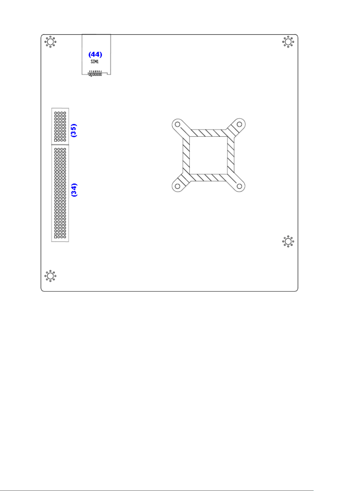
Board Bottom
ACS-2645 User Manual
Figure 2.3: Jumpers and Connectors Location- Bottom

19
2.4 Jumpers Setting and Connectors
JP1
CMOS
Close 1-2
NORMAL (Default)
Close 2-3
Clear CMOS
Pin#
Signal Name
Pin1
VBAT
PIN2
Ground
PS_SEL1
Mode
Close 1-2
DC IN Power (Default)
Close 2-3
ATX 12V_IN (ATX Power)
JP2
Mode (DC_IN)
Close 1-2
Auto Power on (Default)
Close 2-3 or Open 1-2
ATX Power
1. JP1:
(2.0mm Pitch 1X3 Pin Header)CMOS clear jumper, CMOS clear operation will permanently reset old
BIOS settings to factory defaults.
Procedures of CMOS clear:
a) Turn off the system and unplug the power cord from the power outlet.
b) To clear the CMOS settings, use the jumper cap to close pins2 and 3 for about 3
seconds then reinstall the jumper clip back to pins open.
c) Power on the system again.
d) When entering the POST screen, press the <F1> or <DEL> key to enter CMOS Setup
Utility to load optimal defaults.
e) After the above operations, save changes and exit BIOS Setup.
2. BAT1:
(1.25mm Pitch 1X2 Pin wafer connector) 3.0V Li battery is embedded to provide power for CMOS.
3. PS_SEL1(option):
(2.0mm Pitch 1X3 Pin Header),DC in Power and ATX 12V IN Power jumper setting.
4. PS_ON:
(2.0mm Pitch 1X3 Pin Header),ATX Power and Auto Power on jumper setting.
ACS-2645 User Manual

20
5. DCIN:
Pin#
Power Input
Pin1
DC+9V~32V
Pin2
Ground
Pin3
PG
Power Mode
Location : DCIN
(5.4.5.)
Location: ATX12V
(5.4.6.)
Location: ATX1
(5.4.7.)
DC INPUT
(Default)
input
DC9~32V
output
DC 12V
NC
ATX Power
(option)
NC
Input (DC12V)
ATX Power 2*2P
PSON,GND,5VSB
ATX Power
Pin#
Power output (DCIN)
Pin1
Ground
Pin2
Ground
Pin3
DC+12V
Pin4
DC+12V
Pin#
Signal Name
Pin1
ATX PSON
PIN2
ATX Ground
PIN3
ATX 5VSB
(5.08mm Pitch 1x3 Pin Connector),DC9V ~ DC32V System power input connector。
6. ATX12V:
(2x2 Pin Connector),DC12V System power output connector.
7. ATX1 (option):
(2.0mm Pitch 1X3 Pin wafer connector),connect PSON and 5VSB and Ground signal,support ATX
Power model. Reserved.
ACS-2645 User Manual
21
8. U2:
MODEL
CPU
ASB-M7101T-D2550
Intel Atom D2550 1.86GHz
ASB-M7101B-D2550 (option)
Intel Atom D2550 1.86GHz
ASB-M7101T-N2800 (option)
Intel Atom N2800 1.86GHz
ASB-M7101B-N2800 (option)
Intel Atom N2800 1.86GHz
ASB-M7101T-N2600 (option)
Intel Atom N2600 1.60GHz
ASB-M7101B-N2600 (option)
Intel Atom N2600 1.60GHz
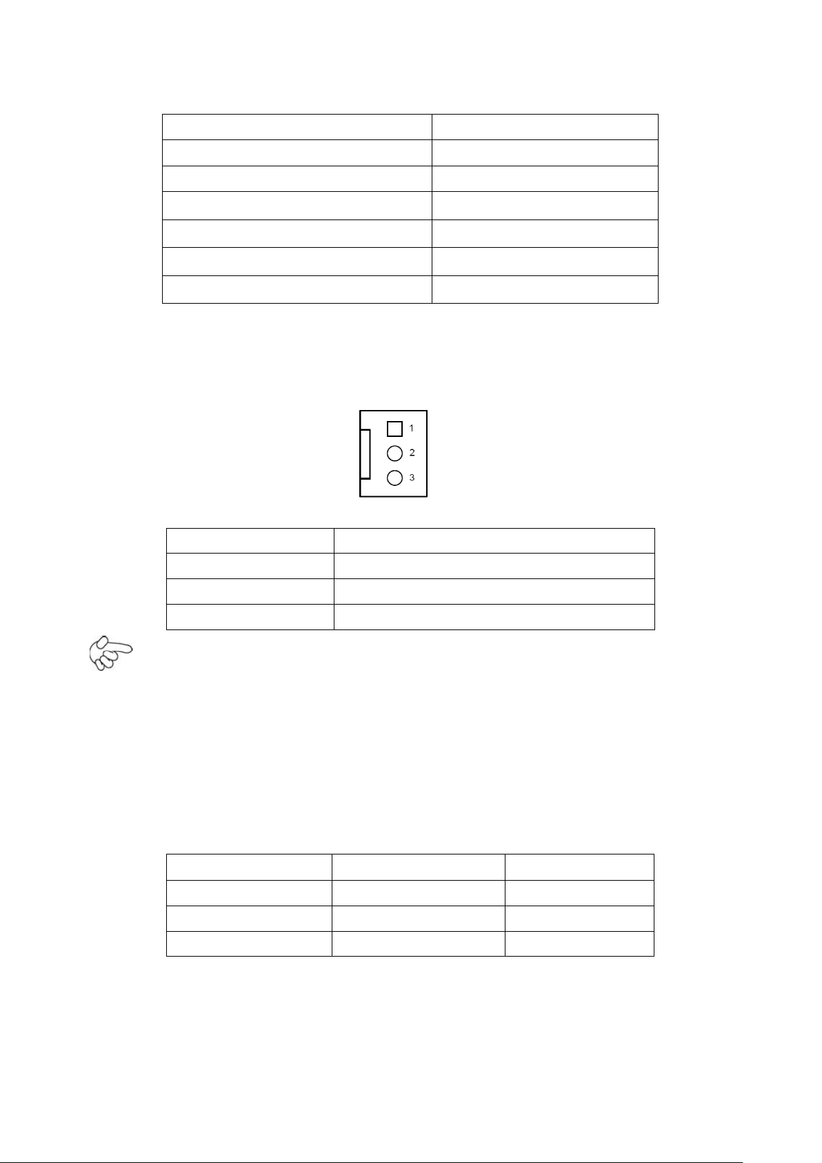
Pin#
Signal Name
1
Ground
2
VCC
3
Rotation detection
MODEL
Socket
Memory
ASB-M7101-D2550
SODIMM1/SODIMM2
Up to 4GB
ASB-M7101-N2800
SODIMM1/SODIMM2
Up to 4GB
ASB-M7101-N2600
SODIMM1
Up to 2GB
(FCBGA559), onboard CPU .
9. CPU_FAN/SYS_FAN:
(2.54mm Pitch 1x3 Pin wafer connector),Fan connector, cooling fans can be connected directly for
use. You may set the rotation condition of cooling fan in menu of BIOS CMOS Setup.
Note:
Output power of cooling fan must be limited under 5W.
10. SODIMM1/SODIMM2:
(SO-DIMM 204Pin socket), DDRIII memory socket, the socket is located at the Top of the board and
supports 204Pin 1.5V DDRIII 800/1066MHz FSB SO-DIMM memory module up to 4GB or 2GB. The
single RAM use SODIMM1 Slot.
11. VGA:
(CRT DB15 Connector),Video Graphic Array Port, provide high-quality video output. they can not
work at the same time for VGA and VGA_PH.
ACS-2645 User Manual
 Loading...