


TA-500 Badge Reader
Installation and Configuration Guide
DSI Version 2.0 – 2.3

11/03/2009
AD0842-20705
Copyright © 2006
API Healthcare Corporation
This document is copyrighted by API Healthcare Corporation and all rights are reserved. This document may not, in whole or part, be
reproduced, stored in a retrieval system, or transmitted, in any form or by any means, electronic, mechanical, recording, or otherwise,
without prior written consent from API Healthcare.
Portions of the information contained in this document, respectively, are: Copyright © 2005 Microsoft Corporation, One Microsoft Way,
Redmond, Washington 98052-6399 U.S.A.; Copyright © 2005 Sax Software Corp.; Copyright © 2005 Identify Software, Ltd., All rights
reserved; © 1995-2005 by Actuate Corporation, All rights reserved; and Copyright © 2005 Seagate Technology, LLC now d/b/a Business
Objects SA, All rights reserved. TallPDF.NET and PDFKit.NET are © 2001 TallComponents BV. All rights reserved. TeleTools ActiveX
and VCL controls are Copyright © 1997 ExceleTel, Inc. All rights reserved. Portions of the GoDiagram
Binary Kit are Copyright © 1999 Northwoods Software Corporation. All rights reserved.
Copyright © 2005 Desaware, Inc. All rights reserved. Redistributable DLL files in the NetAdvantage
are Copyright © 2001 Infragistics, Inc. Windsor Corporate Park, 50 MillStone Rd., Building 200 – Suite 150, East Windsor, NJ 08520. All
rights reserved. Portions of the ActiveX controls, respectively, are: Copyright © 2003 Bennet-Tec Information Systems, Inc., All rights
reserved; Copyright © 2005 Data Dynamics, Ltd., All rights reserved; Copyright © DL Technology, Ltd.; Copyright © 1991 – 2005
FarPoint Technologies, Inc.; Copyright © Janus Systems SA de CV; and © Olympus 2005.
The information in this document is subject to change without notice. API Healthcare assumes no responsibility for any errors in this
document Although API Healthcare warrants (per the License Agreement with its Customers) that the System in general will perform in
accordance with Documentation, there may be minor differences in screen formats, report layouts, operating procedures, etc., depending on
each Customer's particular preference and operating environment.
Names and data and all other information used in examples herein are fictitious, unless otherwise noted.
The Desaware Universal .NET StorageTools are
TM
for .NET Windows Forms
TM
.NET Windows Forms Controls
Trademarks
ActiveLink, ActiveRoster, ActiveStaffer, Acuality, api LaborWorkx, API Healthcare, Applicants Navigator, Attendance+, Benefits
Navigator, CalcEngine, DayCare DeductIT, DeductIT, e:HRStats, e:LaborStats, e:StafferStats, EdStats, EdTrack, HR Navigator, HRStats,
HRXpress, LaborStats, LaborVision, myHRaccess, NetXpress, Payroll Navigator, Payrollmation, Position Control Navigator,
ReportXpress, SecurALL, SecurALL Basic, SecurALL Lite, SecurALL Server, SecurStats, StafferStats, Ti meBack, TimeCall, TimeFax,
TimeID, TimePC, TimeStor, TimeView, www.ActiveStaffer, www.ApplicantsNavigator, www.ReportXpress, www.TimePC, and
WorkAgent are either registered trademarks or trademarks of API Healthcare Corporation in the United States. The absence of a name or
logo in the foregoing list does not constitute a waiver of any and all intellectual property rights that API Healthcare. has established in any
of its product, feature, or service names or logos.
Trademarks of API Healthcare Corporation may be used publicly only with written permission from an authorized representative of API
Healthcare– nothing contained in this document should be construed as granting, by implication, laches, estoppel, or otherwise, any license
or right to use, copy, publish, transmit, or modify any trademark of API Healthcare Corporation without such prior written authorization.
Microsoft, Windows, Windows 2003, Windows 2000, Windows XP, Windows CE, Windows 98, and SQL Server are either registered
trademarks or trademarks of Microsoft Corporation in the United States and/or other countries. Oracle is a registered trademark of Oracle
Corporation and/or its affiliates. Adobe, the Adobe Logo, Acrobat, Reader, Flash, and Macromedia are either registered trademarks or
trademarks of Adobe Systems Incorporated in the United States and/or other countries. Canon is a registered trademark or trademark in the
United States and/or other countries. Catalyst Systems and EVALISYS are registered trademarks or trademarks of Catalyst Systems, LLC.
Patient Care Technologies, PtCT, and well.at.home are registered trademarks of Patient Care Technologies, Inc. PKZIP and PKWARE are
trademarks of PKWARE, Inc. Per-Se, ANSOS, and One Staff are registered trademarks or trademarks of Per-Se Technologies, Inc. Res-Q
is a registered trademark of Res-Q Healthcare Systems, Inc. Intel and Dialogic are registered trademarks of Intel Corporation. MicroTouch
is a trademark of MicroTouch Systems, Inc. Adaptec is a trademark of Adaptec, Inc. Nisca is a trademark of Team Nisca. Sun, Sun
Microsystems, the Sun Logo, the Java Coffee Cup Logo, J2RE, J2SE, and Java are trademarks or registered trademarks of Sun
Microsystems, Inc. in the U.S. or other countries.
All other company, product, feature, or service names or logos are the registered trademarks or trademarks of their respective companies.

TABLE OF CONTENTS
THE TA-500 DEVICE .................................................................................................1
SUPPORTING DOCUMENTATION .............................................................................................. 1
PARTS IDENTIFICATION - FRONT ............................................................................................. 2
PARTS IDENTIFICATION – BACK .............................................................................................. 4
PARTS IDENTIFICATION – INSIDE ............................................................................................ 5
MOUNTING BRACKET DIMENSIONS ........................................................................................ 6
COMMUNICATION CONFIGURATION DIAGRAMS ................................................................ 7
DEVICE SPECIFICATIONS ........................................................................................................... 8
FCC RULES ..................................................................................................................................... 9
BADGE REGISTRATION ............................................................................................................. 10
SUCCESSFUL REGISTRATION ........................................................................................... 10
UNSUCCESSFUL REGISTRATION ..................................................................................... 10
RETURNING DEVICE FOR SERVICE ........................................................................................ 11
DEVICE INSTALLATION ......................................................................................13
DEVICE INSTALLATION GUIDELINES .................................................................................... 13
WALL MOUNTING PROCEDURES ............................................................................................ 14
INSTALLATION CONSIDERATIONS ................................................................................. 14
NETWORK CONSIDERATIONS .......................................................................................... 14
INSTALLATION: TA-500 COMMUNICATING VIA POE ................................................. 15
INSTALLATION: TA-500 COMMUNICATING VIA POE LINE INJECTOR ................... 17
CONFIGURATION SETTINGS ..............................................................................21
SUPERVISORS MENU ON DEVICE ........................................................................................... 21
MENU OPTIONS .................................................................................................................... 21
1. TERMINAL ID ............................................................................................................. 21
2. IP SETTINGS ............................................................................................................... 21
3. DEVICE VERSION...................................................................................................... 23
4. RAM & ROM ............................................................................................................... 23
5. DATE AND TIME ....................................................................................................... 23
6. TIME MODE ................................................................................................................ 23
7. DIAGNOSTICS ............................................................................................................ 23
ENTER TO EXIT ............................................................................................................. 25
TELNET MENU ............................................................................................................................. 26
MENU OPTIONS .................................................................................................................... 27
[1] CHANGE NETWORK CONFIGURATION .............................................................. 27
[2] ADVANCED MENU OPTIONS ................................................................................ 28
[3] SAVE CHANGES AND EXIT ................................................................................... 29
[4] EXIT WITHOUT SAVING CHANGES .................................................................... 29
ADDITIONAL FEATURES .....................................................................................31
COMPLETE ENTRY KEY (RAPID ENTRY KEY) ..................................................................... 31
AUTOMATICALLY ACCEPT BADGE REGISTRATION ......................................................... 32
TA-500 ADMINISTRATION UTILITY .................................................................33
INSTALLATION ............................................................................................................................ 33
TA-500 ADMINISTRATOR UTILITY ......................................................................................... 33
PROCEDURES ..........................................................................................................45
PREPARING DEVICE FOR SERVICE ......................................................................................... 45
REMOVING CLOCKINGS FROM TRAINING DEVICE ........................................................... 47
DEVICE CONFIGURATION ........................................................................................................ 48
TROUBLESHOOTING .................................................................................................................. 50

BADGE DOES NOT WORK IN DEVICE ............................................................................. 50
BADGE REGISTRATION ..................................................................................................... 50
DISPLAY WINDOW MESSAGES ........................................................................................ 51
NOT ABLE TO COMMUNICATE WITH THE DEVICE .................................................... 51
PARTS MAINTENANCE .........................................................................................53
CLEANING/SCHEDULED MAINTENANCE ............................................................................. 53
READHEAD-MAGNETIC ..................................................................................................... 53
READ HEAD - BAR CODE ................................................................................................... 53
CASE....................................................................................................................................... 54
BATTERY REPLACEMENT ........................................................................................................ 54
MATERIALS NEEDED ......................................................................................................... 54
REPLACING THE BATTERY .............................................................................................. 54
READ HEAD REPLACEMENT (MAGNETIC OR BAR CODE) ............................................... 57

Chapter 1
THE TA-500 DEVICE
Observe basic safety precautions when using electrical equipment. Please read all instructions
first. Warranty will be void if device is wholly or partially inop erable as a result of not following
these instructions. If you have any questions contact the API Healthcare Customer Support.
This document contains specification, configuration, and wall mounting instructions for the TA-500 series.
Interaction with the device is performed by registering the badge and touching the keypad. The device supports the
use of magnetic, bar code, or proximity badges. The ability to support both magnetic or bar code with proximity o n
one device is also available.
SUPPORTING DOCUMENTATION
1
TA-500 Badge Reader Installation and Configuration Guide
Reviews the hardware specifications, configurations, wall mounting instructions, administration tools, and
device specific utilities.
Device Manager User Guide
Reviews the use of the Device Manager and other Device Tools used for configuring and communicating
with the device on the api LaborWorkx system.
Payrollmation Communications User Manual
Reviews the use of the Payrollmation Series Enterprise Manager and other tool used for configuring and
communicating with the device on the Payrollmation System (NT).
Confidential – API Healthcare Corporation The TA-500 Device
Copyright © 2006. All rights reserved. 2009-11-03
2
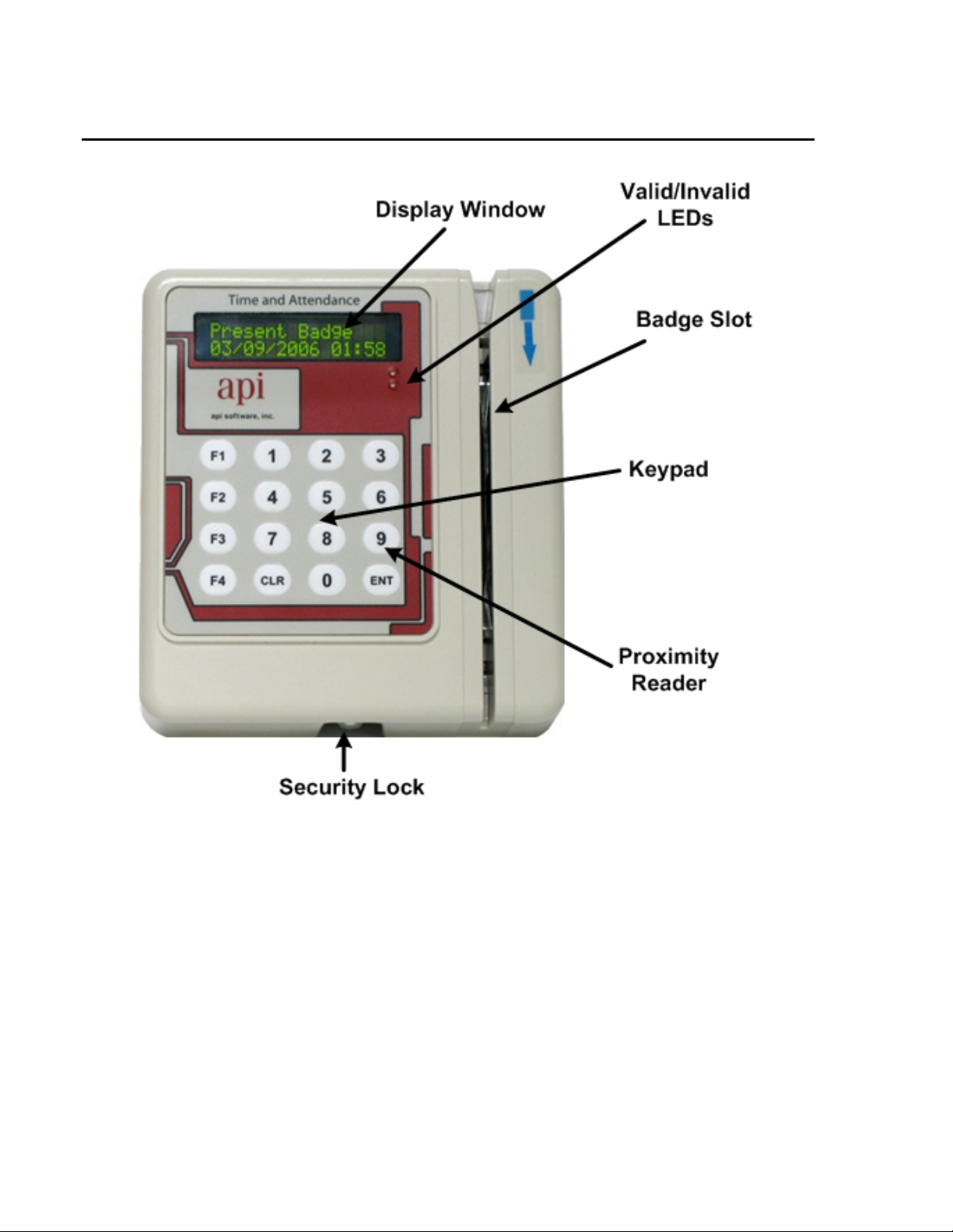
PARTS IDENTIFICATION - FRONT
Display Window The Display Window displays the current date and time and messages identifying the
success or failure a badge registration. Prompts for data entry also display in the window.
Valid/Invalid LEDs The valid and invalid LEDs light to signify valid and invalid entries.
Badge Slot Used with magnetic or bar code badges, the badge is swiped through the slot to register.
The arrow at the top of the slot indicates the direction the magnetic stripe or bar code
should face. This example reflects a magnetic reader. When the device does not contain
a magnetic or bar code reader, the badge slot is not available.
Proximity Reader The Proximity reader is only available on proximity devices. To register a proximity
badge pass the badge in front of the 9-key on the keypad.
TA-500 Badge Reader (DSI Version 2.0-2.3) Confidential – API Healthcare Corporation
Installation and Configuration Guide Copyright © 2006. All rights reserved.

Keypad The keypad is used to enter additional information at the device. Interaction with the
device may include registering additional information about a shift or submitting nonproductive time.
Number Pad ............... Used to record values at the displayed prompts.
CLR Key .................... The Clear Key is used to remove information currently displayed
on the device.
ENT Key .................... The Enter Key is used to save the entered data or to move to the
next prompt.
F1 Key ....................... Provides access to the setup and configuration menu for the device.
Access is granted by depressing the F1 key until the "Supervisor
PIN" prompt displays. Access to the menu is granted only with a
valid PIN.
F2/F3 Key .................. When the In/Out Keys are enabled, the F2 key is used to identify
an In clocking, the F3 Key is used to identify an Out clocking.
F4 Key ....................... Pressing the F4 key accesses the Non Productive data entry. When
the key is depressed, the display changes to "Non Productive
Entry…Please Present Badge". With a successful badge
registration the user is able to record a non-productive entry.
Complete Entry Key .. The F4 key may also be configured to serve as a Complete Entry
key (or Rapid Entry key). When enabled, employees may use this
key to quickly complete a productive entry versus pressing the
ENT key or allowing the device to time out.
Function Keys ............ The four keys located to the left of the keypad may be configured
to automatically fill one prompt with data. In order to use this
feature the Function Keys must be enabled. The data to fill the
prompt must also be configured within the communications
software for each device. If the Rapid Entry Key is enabled, the
F4 key is not available as a function key.
Security Lock This lock provides access to the inside of the unit for wall mounting or network
connection. The lock requires a special key supplied with the device.
Description: Security Key
3
Part Number: SESK01010
Confidential – API Healthcare Corporation The TA-500 Device
Copyright © 2006. All rights reserved. 2009-11-03
4
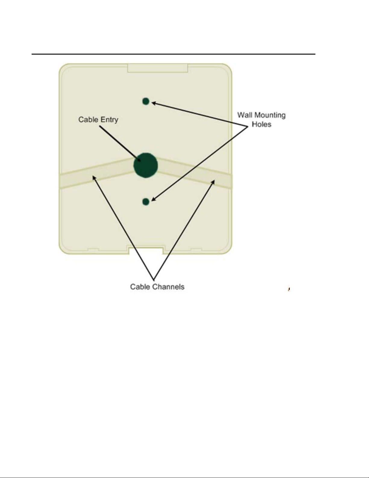
PARTS IDENTIFICATION – BACK
Cable Entry The network cable providing power and network is routed through this location.
Wall Mounting Holes The unit is mounted to the wall. This part of the plate faces the wall.
Cable Channels Channels are provided for mounting the device on a solid surface.
TA-500 Badge Reader (DSI Version 2.0-2.3) Confidential – API Healthcare Corporation
Installation and Configuration Guide Copyright © 2006. All rights reserved.
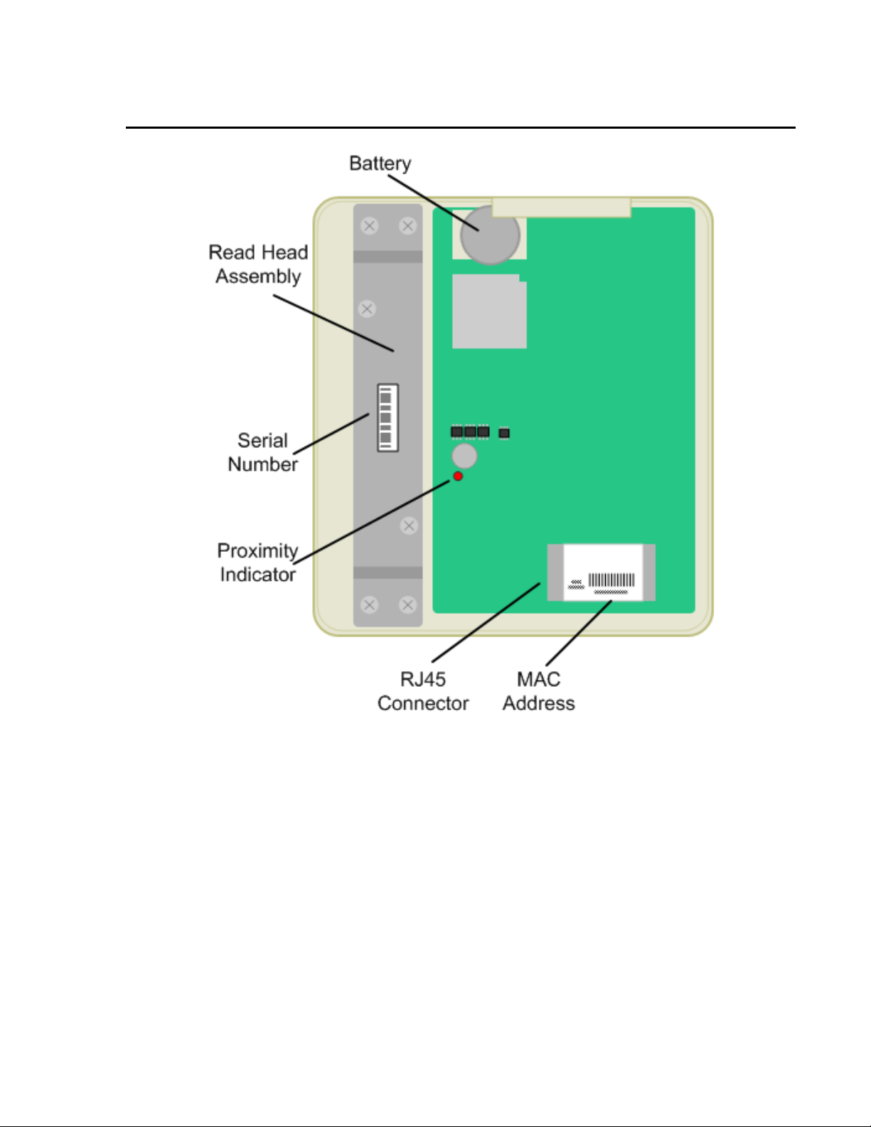
PARTS IDENTIFICATION – INSIDE
5
Battery The location of the battery. The battery keeps the internal clock and calendar
operating when no power is applied.
Read Head Assembly The read head (magnetic or bar code) is located below this plate.
Serial Number The general location of the serial number.
Proximity Indicator The light indicates the activity of the proximity reader, when present.
RJ45 Ethernet Connector The location the network cable is connected to the device. The plug is inserted with
the removal tab visible. The cable is routed through the hole provided on the back
panel.
MAC Address Label Location to identify the MAC address for the unit.
Confidential – API Healthcare Corporation The TA-500 Device
Copyright © 2006. All rights reserved. 2009-11-03
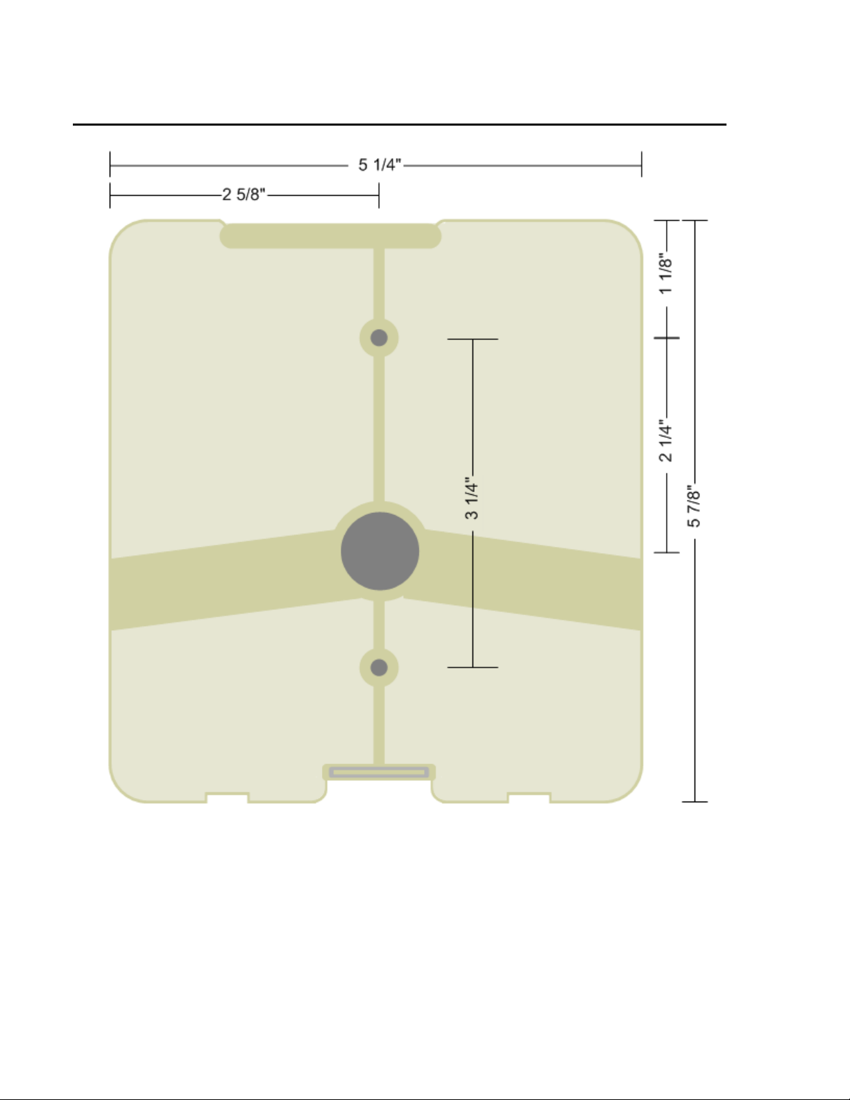
6
MOUNTING BRACKET DIMENSIONS
TA-500 Badge Reader (DSI Version 2.0-2.3) Confidential – API Healthcare Corporation
Installation and Configuration Guide Copyright © 2006. All rights reserved.
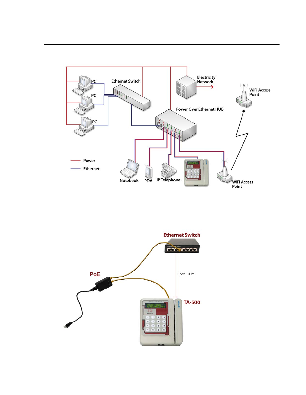
COMMUNICATION CONFIGURATION DIAGRAMS
Power Over Ethernet HUB
7
Power Over Ethernet Line Injector
Confidential – API Healthcare Corporation The TA-500 Device
Copyright © 2006. All rights reserved. 2009-11-03

8
DEVICE SPECIFICATIONS
Display 2 line by 16-character negative mode Liquid Crystal Display.
Clock Dallas DS1307 Real-Time Clock (1):
56 Bytes SRAM (Battery Backed)
Storage 1500 clockings
Keypad Includes digits 0-9, clear key (CLR) enter key (ENT), and four additional function keys
Card Magnetic Stripe: ABA/ISO2, track 2 used
Bar Code: 3 of 9, Interleaved 2 of 5, Code 128 Infrared reader
Proximity: Contact API Healthcare for additional information.
Badge Thickness Magnetic and bar code badges only: 0.76 +- 10%mm.
Battery Panasonic CR2032 3.0V. 3 year life.
The back-up battery is designed to maintain the on board clock only. This battery does
not have sufficient power to accept any badge entries.
Communication IEEE 802.3 Auto-sensing 10/100 Base-T network interface
Full or half duplex(auto-sensing)
Environment 0-40°C (32-104°F), 20-80%RH, indoor, No Condensing
Power TA-500 is IEEE 802.3af compatible (requires a power adapter for Endspan operation)
TA-500 requests a Class 3 Power level
Power supplied by Power Over Ethernet (PoE).
Power source is by Line Injector (used when PoE is not available) or PoE enabled port.
Line Injector: Input: 100-240V, 47-63Hz, 1.0A.
Output: 48VDC, 270ma
Power Cord: 6ft, 3-prong
Power Switch None
Dimensions Height: 5 7/8" (149.225mm) Width: 5 1/4" (133.35mm)
Depth: 2"(50.80mm) Weight: 1.0 lbs (0.45 kg)
Case UV protected high density plastic.
Accessories (2) Mounting Screws, (2) Anchors
(1) Security Case Screw (API Healthcare Part: SESS01010)
(1) Security Key (API Healthcare Part: SESK01010)
(1) PoE Endspan to Midspan Adapter (API Healthcare Part: TADON1010)
(1) PoE Line Injector w/power cord (API Healthcare Part: TAPS01010)
Reader Stand (optional) (API Healthcare Part: FINES1010)
Ferrite (API Healthcare Part: SEFBC0101)
TA-500 Badge Reader (DSI Version 2.0-2.3) Confidential – API Healthcare Corporation
Installation and Configuration Guide Copyright © 2006. All rights reserved.

FCC RULES
FCC Interference Statement (Part 15.105 (a))
This equipment has been tested and found to comply with the limits for a Class A digital device, pursuant to Part 15
of the FCC Rules. These limits are designed to provide reasonable protection against harmful interference when the
equipment is operated in a commercial environment. This equipment generates, uses, and can radiate radio
frequency energy and, if not installed and used in accordance with the instruction manual, may cause harmful
interference to radio communications. Operation of this equipment in a residential area is likely to cause harmful
interference in which case the user is required to correct the interference at his/her own expense.
FCC Warning:
Changes or modifications not expressly approved by the manufacturer responsible for compliance could void the
end-user’s authority to operate this equipment.
The following also applies if one of the following optional proximity type badge readers are installed:
Contains FCC ID: W7N-PROXIC01 (iCLASS)
Contains FCC ID: W7N-PROXIN01 (Indala)
Contains FCC ID: W7N-PROXHI01 (HID PROX)
Contains FCC ID: W7N-PROXAW01 (AWID)
Compliance Statement (Part 15.19)
This device complies with Part 15 of the FCC Rules.
Operation is subject to the following two conditions:
1. This device may not cause harmful interference, and
2. This device must accept any interference received, including interference that may cause undesired operation.
Warning (Part 15.21)
Changes or modifications not expressly approved by the party responsible for compliance could void the user’s
authority to operate the equipment.
FCC Interference Statement (Part 15.105 (b))
This equipment has been tested and found to comply with the limits for a Class B digital device, pursuant to Part 15
of the FCC Rules. These limits are designed to provide reasonable protection against harmful interference in a
residential installation. This equipment generates uses and can radiate radio frequency energy and, if not installed
and used in accordance with the instructions, may cause harmful interference to radio communications. However,
there is no guarantee that interference will not occur in a particular installation. If this equipment does cause
harmful interference to radio or television reception, which can be determined by turning the equipment off and on,
the user is encouraged to try to correct the interference by one of the following measures:
− Reorient or relocate the receiving antenna.
− Increase the separation between the equipment and receiver.
− Connect the equipment into an outlet on a circuit different from that to which the receiver is connected.
− Consult the dealer or an experienced radio/TV technician for help.
9
Confidential – API Healthcare Corporation The TA-500 Device
Copyright © 2006. All rights reserved. 2009-11-03

10
BADGE REGISTRATION
The following summarizes the registration of the badge:
Magnetic Holding the magnetic stripe away from the display window (facing the blue arrow), insert and
slide the badge through the device's vertical slot in a smooth downward motion.
Bar code Holding the bar code away from the display window (facing the blue arrow), insert and slide
the badge through the device's vertical slot in a smooth downward motion.
Proximity Holding the badge in front of the device up to two inches away, pass the badge over the 9 key
on the keypad.
Registration at the device is indicated by the following:
Lights A green light indicates a badge was registered. A red light indicates an error in registration.
Sound The valid audible tone sounds with a valid registration, the invalid audible tone sounds with
an unsuccessful registration. Please note the sound volume cannot be adjusted.
Display The first prompt for data is displayed with a valid registration or a message displays
indicating the reason for an invalid registration.
SUCCESSFUL REGISTRATION
The following indicates a successful registration:
• The valid LED displays green.
• The valid audible tone is sounded.
• The display window changes to the first data entry prompt.
UNSUCCESSFUL REGISTRATION
The following indicate an unsuccessful swipe.
• No response from the device.
or
• The invalid LED displays red.
• The invalid audible tone is sounded.
• The message in the display window indicates the reason for the invalid entry.
#
Most unsuccessful swipes occur due to the badge being swiped too quickly, too slowly, or inserted in the
wrong direction. When the badge is swiped unsuccessfully, register the badge again.
TA-500 Badge Reader (DSI Version 2.0-2.3) Confidential – API Healthcare Corporation
Installation and Configuration Guide Copyright © 2006. All rights reserved.

RETURNING DEVICE FOR SERVICE
Prior to returning a device to API Healthcare for service, contact API Healthcare Customer Support. A
representative reviews several troubleshooting steps with you. In the event the device mu st be returned to API
Healthcare for service, a Return of Merchandise Authorization (RMA) Number must be issued.
IMPORTANT:
• Any equipment received without an RMA number is returned to the customer without review.
• If possible, use the original packaging materials when returning devices for service. This includes the box,
anti-static bag, and Styrofoam holders.
• When the device is mounted to a wall, the back plate does not need to be returned with the device. The
device unit needs to be packaged in an anti-static bag and packed in a manner to prevent damage during
shipping.
11
Confidential – API Healthcare Corporation The TA-500 Device
Copyright © 2006. All rights reserved. 2009-11-03

12
Notes
TA-500 Badge Reader (DSI Version 2.0-2.3) Confidential – API Healthcare Corporation
Installation and Configuration Guide Copyright © 2006. All rights reserved.

Chapter 2
DEVICE INSTALLATION
DEVICE INSTALLATION GUIDELINES
• Comply with all applicable laws, ordinances, building codes, and zoning regulations.
• For IP communications, the device must be within 100 meters of a network closet.
• Use only the supplied mounting bracket with this device.
• Avoid areas of high magnetism.
• Avoid areas with asbestos or lead.
13
• Avoid areas that can disrupt electrical/network connectivity (i.e. by a MRI lab, large motors, etc.).
• Avoid areas where the unit is in direct sunlight or in locations where the device is subjected to airborne dust,
grease, or in areas of high humidity.
• Slots and openings located in the back and bottom of the case provide necessary ventilation. To ensure reliable
device operation and to protect the device from overheating, ensure these openings are not blocked or covered.
• Avoid placing the device above a radiator or heat register. Leave sufficient space around the device when
installing it to ensure proper ventilation.
• In the event the reader is placed in a quiet zone, disable the sound. Sound may be disabled by using the TA-500
Administrator Utility (v2.0 or greater).
• Place devices in areas of low patient/visitor traffic.
• Install the device in a high employee traffic area, but not too high to avoid congestion.
• The device should not be next to a common entrance especially if the work area is greater than a five-minute
distance.
• Place the device in areas regularly patrolled by security.
• If rules are applicable, place device in sterile environments as needed.
• If your facility has an architectural committee, have the plan reviewed and approved prior to wiring.
• The location must be in accordance with American Disabilities Act.
• To prevent serious damage to the device or injury to a person, do not place the device on an unstable cart, stand,
or table.
• Never spill liquids on the device.
• Do not attempt to service the device yourself. Please refer all servicing to qualified API Healthcare service
personnel.
• Save the original shipping carton and packing material in case you need to ship your device. Be sure to
repackage your device as it was originally packed.
Confidential – API Healthcare Corporation Device Installation
Copyright © 2006. All rights reserved. 2009-02-19
14
WALL MOUNTING PROCEDURES
INSTALLATION CONSIDERATIONS
Review the following considerations before installing the device on any surface.
NOTE: Proper on-site technical and physical considerations must be taken into account based on your needs.
• The mounting area must be flat and vertical. The device's case is designed to provide maximum cooling
when mounted to a flat surface.
• Mount the back panel to wall. Do not add spacers to angle the bracket in any way. This affects the ability
for the device to cool itself and could cause further difficulties affixing the device to the back panel. The
device's case is angled to allow a wide range of users to view the device as long as the back panel is flush
against the wall.
• The back plate cannot be inset into the wall any deeper than the thickness of the bracket itself. Mounting
the back plate too deep results in not being able to attach the device to the back plate.
• Locate and route the Ethernet cable to the device before affixing the device to the back plate. Ensure to
include enough slack in the cable to facilitate easy application and removal of the device. Cables should
not be taut at any time affixing the device to the back plate.
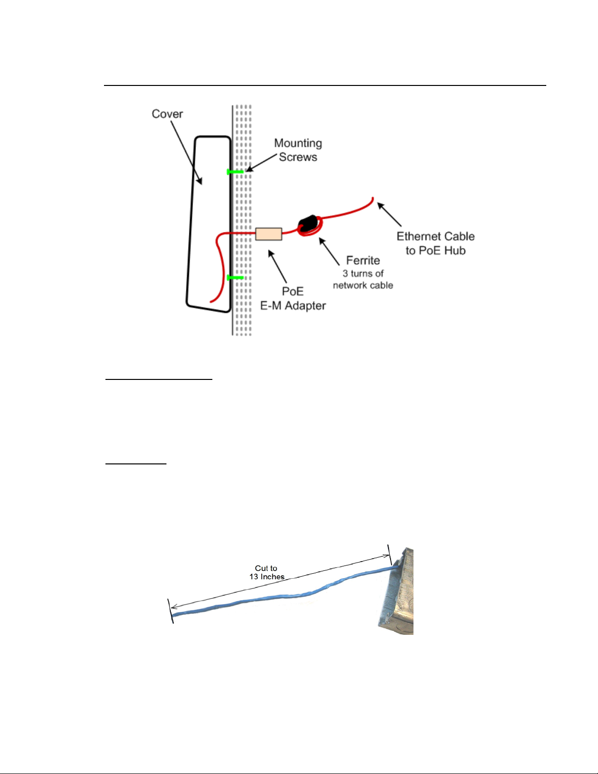
• Installation of the supplied ferrite on the CAT 5 Ethernet cable is required to comply with FCC regulation.
The ferrite material is made to specifically absorb noise in the higher frequencies. The ferrite is installed
on the reader's side of the network, not the data closet side.
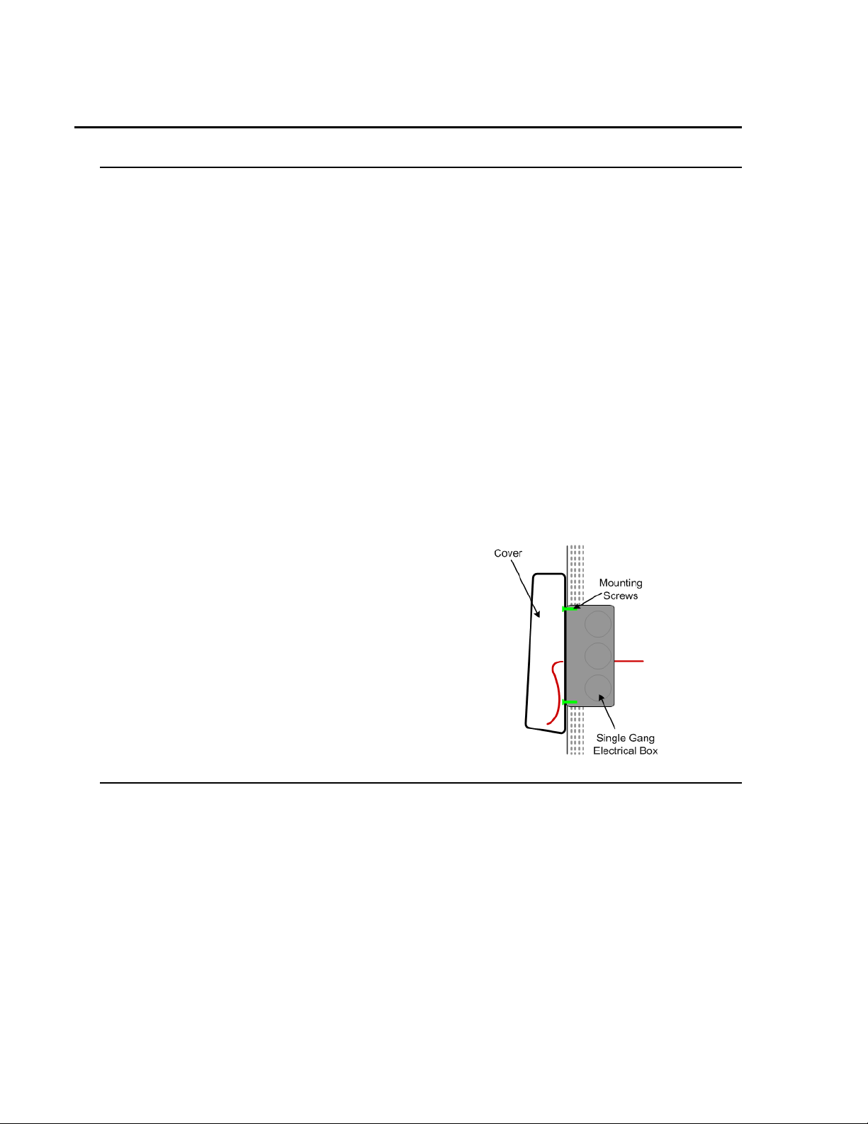
• A Single Gang Electrical box may be used to
house the ferrite and Endspan to Midspan
Adapter (when used).
• For devices requiring the end-user to swipe a
badge, ensure adequate clearance is available to
allow the ID card to pass through the badge slot
properly.
NETWORK CONSIDERATIONS
• The ferrite requires 3 turns of the network cable through it in order to be effective. The ferrite must be
installed on the device side, not the data closet side of the network cable.
• The distance from the ferrite to the Line Injector (when used) follows standard networking guidelines for
distance. The Line Injector does not need to reside by the device, it can reside in the data closet.
TA-500 Badge Reader (DSI Version 2.0-2.3) Confidential – API Healthcare Corporation
Installation and Configuration Guide Copyright © 2006. All rights reserved.
INSTALLATION: TA-500 COMMUNICATING VIA POE
•
15
Obtain the following:
• Device with back plate
• Security Key
• 2 Mounting Screws
• Ferrite
• PoE Endspan to Midspan Adapter
Single Gang Electrical box (optional for stor age)
• Philips Head screw driver.
• Hand drill
• Pencil or other marking tool.
Installation:
1. On the wall perform one of the following:
• Install the Single Gang Electrical box
• Mark the wall where the back plate is to be placed and mark the 2 holes to drill. Drill the 2 mounting
holes.
2. Extend a length of 13 inches to provide ample cable for installation.
Confidential – API Healthcare Corporation Device Installation
Copyright © 2006. All rights reserved. 2009-02-19
16
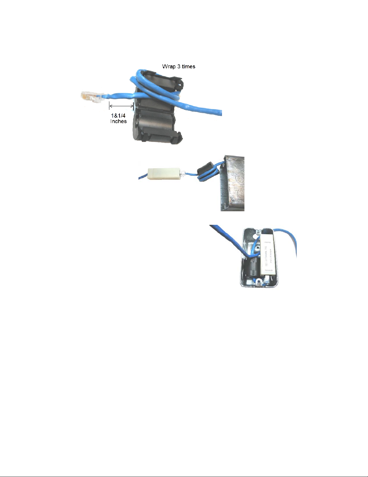
3. Install the ferrite. With 1-¼" of network cable in front of the ferrite, wrap the remaining cable 3 times
around the ferrite. Close the ferrite.
4. Attach the PoE Endspan to
Midspan Adapter.
5. When an electrical box is used, insert the ferrite first,
then the adapter in the box.
6. Route the Ethernet cable from the Endspan to
Midspan Adapter through the entry on the back panel.
7. Mount the back plate to the Electrical box or wall with the 2 supplied screws.
8. Connect the Ethernet cable to the device. Verify information displays on the display window to indicate
the device has power.
9. Slowly lower the unit onto the back plate until the unit is firmly attached.
10. Using the Security Key, tighten the security screw to prevent device from being removed from the wall.
TA-500 Badge Reader (DSI Version 2.0-2.3) Confidential – API Healthcare Corporation
Installation and Configuration Guide Copyright © 2006. All rights reserved.

INSTALLATION: TA-500 COMMUNICATING VIA POE LINE INJECTOR
•
17
Obtain the following:
• Device with back plate
• Security Key
• 2 Mounting Screws
• Ferrite
• Line Injector
Single Gang Electrical box (optional for stor age)
• Philips Head screw driver.
• Hand drill
• Pencil or other marking tool.
Installation:
1. On the wall perform one of the following:
• Install the Single Gang Electrical box
• Mark the wall where the back plate is to be placed and mark the 2 holes to drill. Drill the 2 mounting
holes.
2. Extend a length of 22 inches to provide ample cable for installation.
Confidential – API Healthcare Corporation Device Installation
Copyright © 2006. All rights reserved. 2009-02-19

18
3. Install the ferrite. With 10" of network cable in front of the ferrite, wrap the remaining cable 3 times
around the ferrite. Close the ferrite.
4. When an electrical box is used, insert the ferrite in the box.
5. Route the Ethernet cable through the entry on the back panel.
6. Mount the back plate to the Electrical box or wall with the 2 supplied screws.
7. Connect the Ethernet cable to the device. Verify information displays on the display window to indicate
the device has power.
8. Slowly lower the unit onto the back plate until the unit is firmly attached.
9. Using the Security Key, tighten the security screw to prevent device from being removed from the wall.
TA-500 Badge Reader (DSI Version 2.0-2.3) Confidential – API Healthcare Corporation
Installation and Configuration Guide Copyright © 2006. All rights reserved.

19
Notes
Confidential – API Healthcare Corporation Device Installation
Copyright © 2006. All rights reserved. 2009-02-19

20
Notes
TA-500 Badge Reader (DSI Version 2.0-2.3) Confidential – API Healthcare Corporation
Installation and Configuration Guide Copyright © 2006. All rights reserved.

Chapter 3
CONFIGURATION SETTINGS
Configuration to communicate to the device is performed either at the device or using Telnet.
Note: The Setup Badge used for the Employee Information Station or TA20 badge reader may also be used.
SUPERVISORS MENU ON DEVICE
The Supervisors Menu is available for defining parameters used on the device.
Perform the following to access the Supervisors Menu on the device:
1. Hold down the F1 key until the display changes from 'Present Badge' to 'Supervisor PIN'.
2. Enter the PIN and press the ENT key. The default PIN is '415049'. The value may be configured within the
Supervisors Menu or by depressing the 3 key while booting the device.
Use the F3 key to view the next menu option, the F2 key to view the previous menu option. NOTE: There
is a 4-6 second wait for user input during the menu options. When no input is made, the system
automatically exits the supervisors menu and returns to the default reader state.
MENU OPTIONS
21
1. Terminal ID
1. View Term ID. Press 1 to view the current terminal number configured. Press the ENT key to return to
the Terminal ID menu.
2. Set Term ID. Press 2 to configure a new terminal number. Please note this value is updated
automatically by the communication software with the number configured in the software.
Enter to Exit. Press the ENT to return to the Supervisors Menu.
2. IP Settings
1. View Network. Press 1 to view the current network type setting. Available network types include
DHCP or STATIC. The default setting is DHCP.
1. Network Type. Press 1 to view the configuration on the device for network communications.
Press the ENT key to return to the Network Type menu. Available network types include:
DHCP or STATIC. The default setting is DCHP.
2. Hostname. Press 2 to display the Hostname currently configured on the device. The default is
Cnnnnnn where nnnnnn is the last 6 digits of the device's MAC address. Press the ENT key to
return to the Network Type menu.
Confidential – API Healthcare Corporation Configuration Settings
Copyright © 2006. All rights reserved. 2008-04-29

22
3. MAC Address. Press 3 to display the MAC Address assigned to the device. Press the ENT
key to return to the Network Type menu.
4. IP Address. Press 4 to view the current IP address used by the device. Press the ENT key to
return to the Network Type menu.
5. Subnet. Press 5 to view the current Subnet address used by the device. Press the ENT key to
return to the Network Type menu.
6. Gateway. Press 6 to view the current Gateway address used by the device. Press the ENT key
to return to the Network Type menu.
7. DNS Server. Press 7 to view the current DNS Server IP address used by the device. Press the
ENT key to re turn to the Network Type men u.
8. Remote Port. Press 8 to view the current Remote Port configured on the device. Press the
ENT key to re turn to the Network Type men u.
2. Set Network. Press 2 to configure the network settings.
1. Network Type. Press 2 to view the Set Network Type menu.
1. Set DHCP. Press 1 to configure the device to communicate using DCHP.
2. Set Static. Press 2 to configure the device to communicate using a static IP address.
Enter the IP Address, Subnet, Gateway, DNS Server and Remote Port values. All digits
need to be entered including leading zeroes. Press the CLR key to remove the previously
entered digits. Press the ENT key to save the address.
2. IP Address. Press 2 to enter a valid IP address when the Network Type is set to STATIC. All
digits need to be entered including leading zeroes. Press the CLR key to remove the previously
entered digit. Press the ENT key to save the address.
3. Subnet. Press 3 to enter a valid Subnet address. All digits need to be entered including leading
zeroes. Press the CLR key to remove the previously entered digit. Press the ENT key to save
the address.
4. Gateway. Press 4 to enter a valid Gateway address. All digits need to be entered including
leading zeroes. Press the CLR key to remove the previously entered digit. Press the ENT key
to save the address.
5. DNS Server. Press 5 to enter the DNS Server IP address. Add digits need to be entered
including leading zeros. Press the CLS key to remove the previously entered digit. Press ENT
to save the address.
6. Remote Port. Press 6 to enter a valid port number. When 0 is entered, the value configured
from the communication software is updated to the device. The value may be entered manually;
however it must match the value in the communication software. This value must be greater
than 10001 and less than 65535. Ports 14000 to 14009 are reserved and cannot be used. Press
the CLR key to remove the previously entered digit. Press the ENT key to save the address.
7. Renew DHCS. Press 7 to view the current DNS Server configuration. Press ENT to return to
the IP Settings menu.
Enter to Exit. Press the ENT to return to the Supervisors Menu.
Enter to Exit. Press the ENT to return to the Supervisors Menu.
TA-500 Badge Reader (DSI Version 2.0-2.3) Confidential – API Healthcare Corporation
Installation and Configuration Guide Copyright © 2006. All rights reserved.

3. Device Version
1. App Version. Press 1 to view the current application version number for the program installed on the
device. Press the ENT key to return to the Device Version menu.
2. Boot Version. Press 2 to view the current boot version number for the program installed on the device.
Press the ENT key to return to the Device Version menu.
3. DSI Version. Press 3 to view the current DSI version number for the program installed on the device.
Press the ENT key to return to the Device Version menu.
4. Client Code. Press 4 to view the current client code for the program installed on the device. Press the
ENT key to return to the Device Version menu.
Enter to Exit. Press the ENT to return to the Supervisors Menu.
4. RAM & ROM
1. RAM Version. Press 1 to view the current RAM version number for the program installed on the
device. Press the ENT key to return to the RAM & ROM menu.
2. ROM Version. Press 2 to view the current ROM version number for the program installed on the
device. Press the ENT key to return to the RAM & ROM menu.
23
Enter to Exit. Press the ENT to return to the Supervisors Menu.
5. Date and Time
1. Set Date. Press 1 to change the date. All digits need to be entered including leading zeroes. Press the
CLR key to remove the previous digit. Press the ENT key to save the new date.
2. Set Time. Press 2 to change the time. Enter the date using the 24 hour format. All digits need to be
entered including leading zeroes. Press the CLR key to remove the previous digit. Press the ENT key to
save the new time.
Enter to Exit. Press the ENT to return to the Supervisors Menu.
6. Time Mode
1. 24 Hour Mode. Press 1 to configure the device to display the time with a 24-hour format.
2. 12 Hour Mode. Press 2 to configure the device to display the time with a 12-hour format.
Enter to Exit. Press the ENT to return to the Supervisors Menu.
7. Diagnostics
1. Badging. Press 1 to access the Badge Swipe prompt. Register the badge to view the raw data encoded
on the badge.
1. Raw Data. Press 1 to view the contents encoded on the badge. This option shows all
characters read from the badge.
2. Formatted Data. Press 2 to view the badge number used fr om the badge. This option shows
the badge number as detected by the badge format configuration.
Confidential – API Healthcare Corporation Configuration Settings
Copyright © 2006. All rights reserved. 2008-04-29

24
2. LEDs. Press 2 to test the operation of the red and green LEDs.
1. Green LED. Press 1 to toggle the green LED on and off.
2. Red LED. Press 2 to toggle the red LEN on and off.
3. Both LEDs. Press 3 to toggle both the red and green lights on and off.
Enter to Exit. Press the ENT key to return to the Diagnostics menu.
3. LCD Screen. Press 3 to test the LCD panel display. The top and bottom LCD alternately display.
4. Keypad Press 4 to test the keypad. Press any key on the keypad to display th e results in the display.
5. Buzzer. Press 5 to test the sounds
1. Success Sound. Press 1 to sound the success tone. This is the sound presented when a badge is
successfully registered.
2. Fail Sound. Press 2 to sound the unsuccessful tone. This is the sound presen ted when a
transaction is cancelled.
Enter to Exit. Press the ENT key to return to the Diagnostics menu.
6. Hardware
1. Export Trans. Press 1 to display the menu of options for outputting the data to the serial port.
A special cable must be used to successfully export the data. Contact the API Healthcare
Customer Support for additional information about using this feature.
1. Export NT. Press 1 to export the data in the format for the Payrollmation NT system.
The Clock History conversion tool must be used to import the data to the system.
2. Export LWx. Press 2 to export the data in the format for the api LaborWorkx system.
The Transaction Maintenance utility must be used to import the data to the system.
3. Export Raw. Press 3 to export the raw data. This sends everything present in the
EEPROM chips including valid and invalid data. This capture cannot be used to import
information to the database.
2. Memory Test. Press 2 to test the ability to store data on the device. This process overwrites
the memory devices used on the device. Any transactions stored on the device are removed
when this option is selected.
Erase All?
1. Yes. Press 1 to perform the memory test.
2. No. Press 2 to return you to the Memory Test menu.
Enter to Exit. Press the ENT key to return to the Diagnostics menu.
7. Supervisor PIN. Press 7 to configure the number used to access the Configuration menu. The PIN may
be any number consisting of 4 to 10 digits.
8. Power Monitor.
1. Battery. Press 1 to display the current voltage on the battery.
2. Power In. Press 2 to view the current voltage used by the device. This number fluctuates by a
minimal amount.
Enter to Exit. Press the ENT key to return to the Diagnostics menu.
TA-500 Badge Reader (DSI Version 2.0-2.3) Confidential – API Healthcare Corporation
Installation and Configuration Guide Copyright © 2006. All rights reserved.

9. Reset. Press 9 to display the available menu items for resetting the device.
1. Fac Defaults. Press 1 to reset the device using the factory default. This clears any
configuration data including the IP settings, badge configuration, and prompt data.
2. Reset Device. Press 2 to reset the CPUs operating on the device. This option does not clear
any data, it only restarts the device.
3. IP Firmware Update. Press 3 to update the IP firmware on the device.
4. Reset Password. Press 4 to reset the device password.
Enter to Exit. Press the ENT key to return to the Diagnostics menu.
Enter to Exit. Press the ENT to return to the Supervisors Menu.
Enter to Exit
Press the ENT key to exit the menu and return to the default mode.
25
Confidential – API Healthcare Corporation Configuration Settings
Copyright © 2006. All rights reserved. 2008-04-29

26
TELNET MENU
Ability to configure the device is available by using Telnet.
Perform the following to access the menu via Telnet.
1. Ensure the device is powered and communicating on the network.
2. Open a Command Prompt window. From the Start menu select All Programs, Accessories, and then
Command Prompt.
3. Enter one of the following commands:
"telnet Cnnnnnn 9999" where Cnnnnnn is the hostname. The default hostname is Cnnnnnn
where nnnnnn are the last 6 digits of the MAC address on the device.
"telnet #.#.#.# 9999" where #.#.#.# is the IP address configured.
4. When prompted enter the login and password. The login is 'apitech'. The initial password is 'p assword'.
*************************************************
* TA-500 Time & Attendance *
* Telnet Server *
*************************************************
Login: apitech
Password: *******
TA-500 Badge Reader (DSI Version 2.0-2.3) Confidential – API Healthcare Corporation
Installation and Configuration Guide Copyright © 2006. All rights reserved.

MENU OPTIONS
The initial menu displays a summary of the current settings for the device.
CURRENT TA500 DEVICE SETTINGS
------------------------------------------------- MAC Address: 00-11-22-33-44-55
Current IP Address: 1.7.7.170
Current Subnet Mask: 255.255.255.0
Current Gateway: 1.7.7.1
Current DNS: 0.0.0.0
Hostname: C334455
Comms Version: 0.0.0.0
NETWORK CONFIGURATION
--------------------------------------------------NETWORK CONFIG: DHCP
Menu Options:
[1] Change Network Configuration
{2} Advanced Menu Options
[3] Save Changes and Exit
[4] Exit Without Saving Changes
Your Command[1-4]:
27
[1] Change Network Configuration
Enter 1 to change the network configuration. Select whether to configure a static IP address (#1) or DHCP (#2).
Your Command[1 – 4]: 1
Please select address assignment method:
[1] Static
[2] DHCP
When selecting #1 to configure a Static IP address, enter the IP address, Su bnet Mask, and Gateway address
accordingly. Press ENT to move to the next line. When no data is entered, the current setting remains.
Method[1 – 2]: 1
Address assignment set to: Static
Please enter local IP address[x.x.x.x]: 1.7.1.1
IP Address set to:1.7.1.1
Please enter Subnet Mask{x.x.x.x]: 255.255.255.0
Subnet Mask set to:255.255.255.0
Please enter Default Gateway[x.x.x.x]: 1.7.7.7
Gateway set to:1.7.7.7
Please enter DNS Server[x.x.x.x]: 0.0.0.01
Confidential – API Healthcare Corporation Configuration Settings
Copyright © 2006. All rights reserved. 2008-04-29

28
When selecting #2 to configure DHCP; enter the hostname. The default hostname is Cnnnnnn where nnnnnn
is the last six digits of the MAC address. A valid hostname contains 1 to 16 digits. Press ENT to move to the
next line. When no data is entered, the current setting remains.
Method[1 – 2]: 2
Address assignment set to: DHCP
Please enter Hostname:
[2] Advanced Menu Options
CURRENT DEVICE SETTINGS
-------------------------------------------------- MAC Address: 00-11-22-33-44-55
Current IP Address: 1.7.7.170
Current Subnet Mask: 255.255.255.0
Current Gateway: 1.7.7.1
Hostname: C334455
IP PORT CONFIGURATION
-------------------------------------------------- UDP Local Port: 600
UDP Remote Port: 10000
UDP Idle Time: 10
SERIAL PORT SETTINGS
-------------------------------------------------- BAUD rate: 38400
Advanced Menu Options:
[1] Change IP Port Configuration
{2} Restart Device
[3] Load Factory Default Settings
[4] Load Saved Settings
[5] Change Password
[6] Return to Main Menu
[7] Save Changes and Exit
[8] Exit Without Saving Changes
Your Command[1-8]:
TA-500 Badge Reader (DSI Version 2.0-2.3) Confidential – API Healthcare Corporation
Installation and Configuration Guide Copyright © 2006. All rights reserved.

[1] Change IP Port Configuration. Enter 1 to configure the IP Port configuration. Select [2] for UDP. Press
enter to reach the option 'Please enter the UDP remote port. Enter the value and press Enter to complete the
entry. The other settings are not used.
For the Remote Port, when the value is configured with 0, the device acquires the value configured within
the communications software. When the value is configured manually, it must match the value in the
communications software. 0 is the default.
Your Command[1 – 7]: 1
Please select an IP port type:
[1] TCP
[2] UDP
Type[1 – 2]: 2
IP Port set to: UDP
Please enter the UDP local port:
Please enter the UDP remote port(0 for any port): 0
UDP Remote Port set to:10100
Please enter the UDP packet idle time(10ms units):
[2] Restart Device. Enter 2 to reset the CPUs operating on the device. This option does not clear any data, it
only restarts the device.
[3] Load Factory Default Settings. Enter 3 to reset the device using the factory default. This clears any
configuration data including the IP settings, badge configuration, and prompt data.
[4] Load Saved Settings. Enter 4 to reload the settings currently saved on the device.
[5] Change Password. Enter 5 to configure a new device password. Password must be between 1 and 20
characters.
[6] Return to Main Menu. Enter 6 to return to the main menu.
[7] Save changes and Exit. Enter 7 to save changes and exit from the Telnet session.
[8] Exit Without Saving Changes. Enter 8 to exit from the Telnet session without saving any changes.
29
[3] Save Changes and Exit
Select Menu option 3 to save any changes configured and exit the Telnet menu.
[4] Exit Without Saving Changes
Select Menu option 4 to exit the Telnet menu without saving any changes you may have configured.
Confidential – API Healthcare Corporation Configuration Settings
Copyright © 2006. All rights reserved. 2008-04-29

30
Notes
TA-500 Badge Reader (DSI Version 2.0-2.3) Confidential – API Healthcare Corporation
Installation and Configuration Guide Copyright © 2006. All rights reserved.

Chapter 4
ADDITIONAL FEATURES
COMPLETE ENTRY KEY (RAPID ENTRY KEY)
Employees may use this key to quickly complete a productive entry versus pressing the ENT key or allowing the
device to time out.
Badging Example 1
• Swipe badge
• Press the F4 key to complete the entry
Badging Example 2
31
• Swipe badge
• Enter Special Code entry
• Press the F4 key to complete the entry
The Complete Key (Rapid Key) is configurable on each device. When enabled, the F4 key is not available for a
function key. Perform the following to enable/disable this key.
1. Log into theTA500 Administrator Utility.
2. Select the 'Update Reader Information' option.
3. Select the 'Update Reader Configuration' option.
4. In the Transaction Config section, click on the Rapid Key Enabled option to enable the feature. To disable,
click the Rapid Entry Enabled option to remove the check mark.
5. Click the Next button to continue with the reader configuration. Click Cancel to abort the process without
saving the new settings.
6. Click Finish to exit the utility.
Confidential – API Healthcare Corporation Additional Features
Copyright © 2006. All rights reserved. 2008-04-29

32
AUTOMATICALLY ACCEPT BADGE REGISTRATION
The typical operation of the badge reader is when a badge is registered at the device, additional prompts for
information display. When no entry for these prompts is entered, the registration is automatically accepted after
several seconds of inactivity. The employee may also select the Complete Key (Rapid Entry Key) F4, when
enabled, to record the transaction.
For devices where no additional prompt entry is used, the device may be configured to automatically accept the
badge registration without additional activity. The interaction with the device would be:
Device Display: PRESENT BADGE
Employee registers badge.
Device Display: TRANSACTION ACCEPTED
Note: This feature should not be used on devices where special code entry or labor distribution changes for
productive entries are needed.
Note: Entry for non-productive entry remains the same.
Perform the following to enable/disable the Auto-Accept Feature
1. Log into the TA500 Administrator Utility.
2. Select the 'Update Reader Information' option.
3. Select the 'Update Reader Configuration' option.
4. In the Transaction Config section, click on the Auto Accept Transaction option to enable the feature. To
disable, click the Auto Accept Transaction option to remove the check mark.
5. Click the Next button to continue with the reader configuration. Click Cancel to abort the process without
saving the new settings.
6. Click Finish to exit the utility.
TA-500 Badge Reader (DSI Version 2.0-2.3) Confidential – API Healthcare Corporation
Installation and Configuration Guide Copyright © 2006. All rights reserved.

Chapter 5
T A-500 ADMINISTRA TION UTILITY
The TA-500 Administration Utility provides a means for configuring and verifying the current con figuration of your
TA-500 device. This stand-alone utility may connect to a device configured in the system database or manually by
the device Hostname/IP address.
INSTALLATION
Workstation requirements include:
• Microsoft
• Microsoft
1. Execute the setup TA500AdminSetup.exe from the ..\Setups\TA500 Utilities\API TA500 Administrator Utility
folder. The following prompts for information appear:
Welcome Select Next to continue.
Ready To Install Select whether or not to place a shortcut on the desktop. Select Next to
Installation Complete Select Finish to exit the setup.
2. Oracle databases only. Execute ORACLE_NET.MSI to install necessary files to connect with an Oracle
database. The files are located within the following folder:
TA-500 ADMINISTRATOR UTILITY
®
Windows® 2000 or greater
®
.NET Framework 1.1 (Service Pack 1)
continue.
33
In order to use the TA-500 Administrator Utility, either of the following information is required to communicate
with the device.
• The database server name and database name where the device is configured.
• The hostname or IP address of the device.
TO PROCESS:
1. From the Start Menu, open the API TA-500 Administrator folder and select TA-500 Administrator, or select the
icon from the desktop (when installed).
2. On the initial Welcome screen, select Next to continue.
Confidential – API Healthcare Corporation TA-500 Administration Utility
Copyright © 2006. All rights reserved. 2009-04-30

34
3. Select the option for choosing the devices, enter the necessary information, then select Next to continue.
Choose devices from a list in my database.
Use this option to connect to your Time and Attendance database and choose from the list of configured
devices. Select the type of database (SQL or Oracle) in use, then enter the connection information.
SQL Database
Server Name of the server the time and attendance database resides.
Authentication Choose the desired login criteria, by Windows Authentication or SQL Server
Authentication (requires a database user and password to be entered).
Database Name of the Payrollmation System database.
Oracle Database
Service The service information for the time and attendance database server.
Username Valid database user login name.
Password Vali d pass wor d associat ed with database username.
I want to specify the devices manually
Use this option to specify the devices manually, by either host name or IP address.
TA-500 Badge Reader (DSI Version 2.0-2.3) Confidential – API Healthcare Corporation
Installation and Configuration Guide Copyright © 2006. All rights reserved.

4. Select the option to perform operations on the device, then select Next to continue.
35
Express Setup
This option is not available when the 'I want to specify the devices manually option' is selected on the
previous screen.
Use this option to automatically setup the selected device. The latest values stored in the database are used
or the user is prompted for information when necessary.
Confidential – API Healthcare Corporation TA-500 Administration Utility
Copyright © 2006. All rights reserved. 2009-04-30

36
The following configuration screen appears when the Express Setup or Update Reader Information option
is selected.
Use Database Values
Indicate whether to not the information for this section is obtained from the
database.
RAM Version Version number referenced for the RAM. The value needs to match the
database. For customers with the TA20 model badge reader, this value must
match the value on the TA20. For all other customers use the value API-B22
ROM Version Version number referenced for the ROM. This value needs to match the
database. Value is always B01 for a time and attendance device.
Client Code The client code assigned to the customer's system. Obtain from the
database or enter accordingly.
Misc Config Section
Sound Enabled Indicator whether or not the sound is enabled. The sound includes the
beeps for valid and invalid entry.
api LaborWorkx
®
Mode This option only displays when the devices are specified manually.
Use this option to configure the device for the api LaborWorkx system.
This option should not be used when the device is communicating with the
Payrollmation Series NT system.
TA-500 Badge Reader (DSI Version 2.0-2.3) Confidential – API Healthcare Corporation
Installation and Configuration Guide Copyright © 2006. All rights reserved.

37
Badge Type Enabled
Magnetic Indicate whether or not the magnetic swipe is enabled on the device. When
Barcode Indicate whether or not the barcode swipe is enabled on the device. When
not checked, the magnetic swipe is disabled.
not checked, the barcode swipe is disabled.
Proximity Indicate whether or not the proximity reader is enabled on the device.
When not checked, reading proximity badges is disabled.
Transaction Config
Rapid Entry Enabled When checked, the F4 key is used as a Complete Entry Key. Employees
Legacy Special Code When checked, the Special Code entry requires all special codes to be
Entry entered as one value. Leading zeroes are needed when more than one 1-
In/Out Enabled When checked, the F2 and F3 keys are required for badging in or out. F2
Auto Accept Transaction For devices where no additional prompt entry is used, the device may be
NP Max Future Months When non-productive entry is enabled on the device, entry is limited to only
NP Max Past Months When non-productive entry is enabled on the device, entry is limited to only
iCLASS
may use this key to quickly complete a productive entry versus pressing the
ENT key or allowing the device to time out. When enabled, only F1 – F3
are available for configuring Hot Keys.
digit code is entered, for example enter codes 3 and 5 you would enter 305.
This activity is the same as the TA20 badge reader.
When not checked, the Special Code prompts individually for each code.
This activity is the same as the EIS Badge Reader.
indicates an in clocking, F3 an out clocking. After the badge is swiped, the
user presses the F2 or F3 key. The additional prompts for data entry display
after the F2 or F3 key is pressed.
configured to automatically accept the badge registration without additional
activity. After the badge is registered the device displays 'Transaction
Accepted'. No prompts display.
3 months in the future by default. To extend this timeframe, update this
value for the number of months to permit data entry.
1 months in the past by default. To extend this timeframe, update this value
for the number of months to permit data entry.
®
Enabled When iCLASS technology is used, this option must be enabled. This
setting in conjunction with the badge format configured on the device is
used to decode the badge.
Confidential – API Healthcare Corporation TA-500 Administration Utility
Copyright © 2006. All rights reserved. 2009-04-30

38
Update Reader Information
Select this option to configure various settings on the device. The following options are available for
selection. More than one option may be selected.
Update DSI Select this option to update the DSI file on the device, only devices
with a DSI not matching the file selected are updated. Choosing the
Force DSI Update forces the file to be updated on the device regardless
of the current version.
Enter the location and name of the DSI file to update. Use the available
Browse button to locate the file.
TA-500 Badge Reader (DSI Version 2.0-2.3) Confidential – API Healthcare Corporation
Installation and Configuration Guide Copyright © 2006. All rights reserved.

Update Badge Formats Select this option to upload a badge file (Badge.dat) to the device.
39
Enter the location and name of the Badge.dat to update. Use the
available Browse button to locate the file.
Note: For the api LaborWorkx system the badge format may also be
updated by using the Update Badge File option in the Device
Manager.
Update Reader Configuration Select this option to configure additional reader options and features.
Refer to the previous section – Express Setup for information regarding
the available configuration settings.
Set Date/Time Select this option to update the date and time on the device. The date
and time may also be set by selecting the Set Time option in the
communication software.
Get Reader Information
Select this option to retrieve information from the TA-500 device(s). The following options are available
for selection. More than on e option may be selected.
Confidential – API Healthcare Corporation TA-500 Administration Utility
Copyright © 2006. All rights reserved. 2009-04-30

40
Get Version Select this option to retrieve information regarding the current DSI
version operating on the device.
Get Badge Formats Select this option to retrieve the current badge format configured on the
device.
Get Reader Configuration Select this optio n to retrieve information regarding the various reader
configuration settings.
Export Transactions
This option provides the ability to export transactions from the device to format specified. The following
options are available for selection. Only one may be chosen.
RAW Format Export Select this option to export all transactions to a non-specific format.
The file is created in the directory indicated.
Payrollmation Format Export Select this option to export transactions to the format read by the
Payrollmation Series NT system. The file is created in the directory
indicated.
api LaborWorkx Format Export Select this option to export transactions to the format read by the api
LaborWorkx system. The file is created in the directory indicated.
Export Directory Enter the location to create the export file or use the available Browse
button to select. The default directory is C:\Program Files\API TA-
500 Administrator\TA-500 Administrator.
TA-500 Badge Reader (DSI Version 2.0-2.3) Confidential – API Healthcare Corporation
Installation and Configuration Guide Copyright © 2006. All rights reserved.

5. Select the device(s) to configure then Next to continue. Only devices listed in the Selected Devices window are
updated. Review the following to become familiar with the various screen functions.
When the 'Choose devices from a list in my database ' option is selected.
41
Devices Window Displays all devices currently online and configured within the database.
The available information includes the number assigned to the device, the
description, and the IP address/host name assigned to the device.
Selected Devices Window Displays all devices currently selected to be updated. The information
displayed includes the number assigned to the device, the description, and
the IP address/host name assigned to the device.
Add button Left mouse click once on the device in the Devices window, then select
Add to add the device to the Selected Devices window. Double clicking on
the device in the Devices window also adds it.
Add All button Selecting this button adds all devices to the Selected Devices window.
Requery Selecting this button refreshes the list of available devices with current
connectivity.
Remove Within the Selected Devices window, left mouse click once on the device to
select, then select the Remove button to eliminate it from the selected
devices. Double clicking on the device in the Selected Devices window
also removes it.
Remove All Choosing this option clears all devices from the Selected Devices list.
Confidential – API Healthcare Corporation TA-500 Administration Utility
Copyright © 2006. All rights reserved. 2009-04-30

42
When the 'I want to specify the manually' option is selected.
Add button Enter the host name or IP address of the Ta-500 device in the data entry
field, then click Add to add the device to the Selected Devices window.
Pressing the ENT key also adds the device to the Selected Devices listing.
Please note, communication needs to be established to the device in order to
add it.
Selected Devices Window Displays all devices currently selected to be updated. The information
displayed includes the host name and IP address assigned to the device.
Remove Within the Selected Devices window, left mouse click once on the device to
select, then select the Remove button to eliminate it from the selected
devices. Double clicking on the device in the Selected Devices window
also removes it.
Remove All Choosing this option clears all devices from the Selected Devices list.
TA-500 Badge Reader (DSI Version 2.0-2.3) Confidential – API Healthcare Corporation
Installation and Configuration Guide Copyright © 2006. All rights reserved.

6. All selected devices are listed with the device id, device name, address, status, and overall progress. Select
Next to start the update process. The Status and Overall Progress fields are updated during the processing.
The devices are processed in groups. The arrow keys to the right of the display may be used to move devices in
the list, allowing you to order the devices in a different order. Left mouse click once on the record in the list to
select, then select the appropriate button to move down one position
top of the list
, or to the bottom of the list .
, move up one position , move to the
43
7. At the completion of the process, the final status is listed. Review the available report for additional details.
Confidential – API Healthcare Corporation TA-500 Administration Utility
Copyright © 2006. All rights reserved. 2009-04-30

44
Notes
TA-500 Badge Reader (DSI Version 2.0-2.3) Confidential – API Healthcare Corporation
Installation and Configuration Guide Copyright © 2006. All rights reserved.

Chapter 6
PROCEDURES
PREPARING DEVICE FOR SERVICE
Use the Supervisor Menu on the device or connect via Telnet to configure the following information:
1. Network Type. Configure the method the device is communicating; either by DHCP (default setting) or
with a static IP address.
Supervisor Menu
Option #2 IP Settings, #1 Network Type, #2 Set Network
Telnet Menu
Option #1 Change Network Configuration
2. Network Settings.
When communicating via DHCP configure the Hostname (the default is Cnnnnnn where nnnnnn is the last
6 digits of the device's MAC address.
45
Supervisor Menu
Option #2 IP Settings, #1 Network Type, #2 Hostname (view only)
Telnet Menu
Option #1 Change Network Configuration, #2 DHCP, press enter to save the default.
When communicating via a static IP address, configure the IP address, Subnet, and Gateway.
Supervisor Menu
Option #2 IP Settings, #1 Network Type, #4 IP Address, #2 Set IP Addr.
Option #2 IP Settings, #1 Network Type, #5 Su bnet , #2 Set Su bnet .
Option #2 IP Settings, #1 Network Type, #6 Gateway, #2 Set Gateway.
Telnet Menu
Option #1 Change Network Configuration, #1 Static. Enter the IP address, Subnet, and Gateway
or press enter to save the default.
3. Remote Port. This value must be unique for each device. The value must be greater than 10001 and less
than 65535, ports 14000 and 14009 are reserved and cannot be used.
The value may be set to 0 on the device. The device acquires the value from the communications software
automatically.
Supervisor Menu
Option #2 IP Settings, #8 Remote Port, #2 Set IP Port.
Telnet Menu
Option #2 Advanced Menu Options, #2 UDP, press Enter to reach the prompt 'Please Enter the
UDP remote port' option. Enter the value and press Enter to use the default settings for the
remaining prompts.
Confidential – API Healthcare Corporation Procedures
Copyright © 2006. All rights reserved. 2008-04-29

46
4. Communication Software. Within the communication software, add the device if does not currently exist.
api LaborWorkx System
Version 8.01.04.02 and greater add the device with the following settings:
Hardware Classification: Series 500
IP Device Series: EIS
Version 8.01.04.01 and less add the device with the following settings:
Hardware Classification: TA20
IP Device Series: L
Payrollmation System (NT)
Release 6.05.60 and greater add the device with the followi ng set t i ngs :
Reader Type: TA500 Reader
Internet Protocol Port: Fixed IP Address or DHC P
Release 6.05.50 and less add the device with the following settings:
Reader Type: TA20 Reader
Internet Protocol Port: L Series (Fixed IP Address) or L Series (DHCP)
5. TA-500 Administrator Utility. The following features are available from the utility.
Upload Badge.Dat (Payrollmation S eries NT) – configures the device with the customer's badge
format.
Sound – The beeps are enabled by default. The device may be silenced by disabling the sound.
In/Out Keys – When an In code or Out code is required to be entered with the appropriate
clocking. By default, this feature is disabled.
Rapid Entry Enabled – Configures the F4 key to complete a productive entry. The default is for
this key to not be enabled.
Legacy Special Code Entry– Configure the special code prompt to prompt for codes as one entry
(like the TA20). The default is to prompt for the codes as separate prompts.
Auto Accept Transaction – Set the device to automatically accept transactions without prompting
for additional information. The default is for this feature to be disabled.
6. Communication Software. Perform the following tasks to prepare the device for service.
Status Test – ensures the system can communicate with the device.
Upload DSI (api LaborWorkx only) – this updates the da tabase with the DSI version currently
running on the device.
Upload Badge File (api LaborWorkx only) – configures the device with the customer's badge
format.
Set Prompts – downloads your system prompt configuration to the device.
For the api LaborWorkx system a transaction definition file needs to exist for
clocking and calendar entries. Refer to the Transaction Definition Configuration
guide for additional information.
Set Non Productive – enable the Non Productive key (if used).
Set Hot Keys – configures the function keys (if used). Only 4 keys are available on the device.
Set Date/Time – updates the current date and time of the communications station to the device.
Set Time Mode – configures the device to display 12 or 24 hour format.
Reboot – reboots the device. This ensures all updated files are in use.
TA-500 Badge Reader (DSI Version 2.0-2.3) Confidential – API Healthcare Corporation
Installation and Configuration Guide Copyright © 2006. All rights reserved.

REMOVING CLOCKINGS FROM TRAINING DEVICE
To configure a device for training purposes, configure as you would for any live device.
Badgings occurring during training are typically not posted to the live environment. To prevent any badgings from
being posted in the system, the device needs to be de-activated within the communications software. A device can
hold approximately 1500 badgings before it becomes full.
After a period of time, a training device may become full or need to be used in the live environment. To ensure the
badgings in the device are not posted to the live environment, perform the following to remove the information from
the device.
1. Access the Supervisor Menu on the device by depressing the F1 key until the display changes from 'Present
Badge' to 'Supervisor PIN'.
2. Enter the PIN and press the ENT key. The default PIN is '415049'.
3. Press 7 to access the Diagnostics Menu.
4. Press 6 to access the Memory Test.
5. When prompted to Erase All? press 2 for Yes.
6. Press ENT to Exit the Supervisor Menu.
The device is now ready for use. The following information remains unchanged on the device.
• Date and Time
• Prompts
• Network Configuration
• Badge Format
47
Confidential – API Healthcare Corporation Procedures
Copyright © 2006. All rights reserved. 2008-04-29

48
DEVICE CONFIGURATION
The following indicates the location for configuring the various device settings.
Automatically Accept Transaction
• Use the TA-500 Administrator to enable/disable the feature. Use the Update Reader Configuration
option. When enabled, no prompts for information appear.
Badge Format
• For the api LaborWorkx System log into the Device Manager and use the Upload Badge File option.
The information is updated from the database.
• For the Payrollmation Series NT use the TA-500 Administrator Utility to upload the badge file. A
copy of the badge.dat to update must be available.
Complete Entry (Rapid Entry) Key
• Use the TA-500 Administrator to enable/disable the key. Use the Update Reader Configuration option.
When enabled, F4 key cannot be used as a Function key.
Date and Time
• Use the Communication software to set the Date and Time.
• Supervisor Menu, Option #5 Date and Time.
• From the TA-500 Administrator Utility/Update Reader Configuration option.
DSI – Updating File
• For the api LaborWorkx System log into the Device Manager and use the Upload DSI option.
• For the Payrollmation Series NT system, use the TA-500 Administrator Utility.
DSI Version
• Within the TA-500 Administrator Utility select the Get Reader Information/Get Version option.
• Supervisor Menu, Option #3 Device Versio n, # 3 DSI Ve rsion.
• Telnet Menu, API 500 Series section of the Main Menu.
• Use the Communication software to view the properties.
Function Keys (Enable/Configure)
• Within the Communication Software, configure the value and description for each device and upload
to the device.
In/Out Key
• Use the TA-500 Administrator to enable/disable the keys. Use the Update Reader Configuration
option. When enabled, the employee swipes the badge and is prompted to indicate the type of
clocking, either F2 (In) or F3 (Out).
Network Configuration
• Supervisor Menu, Option #2 IP Settings.
• Telnet Menu, Option #1 Change Network Configuration.
Non-Productive Entry (Enable/Disable)
• Within the Communication Software enable the Non Productive entry.
TA-500 Badge Reader (DSI Version 2.0-2.3) Confidential – API Healthcare Corporation
Installation and Configuration Guide Copyright © 2006. All rights reserved.

Reset Device
• Supervisor Menu, option #7 Diagnostics, #9 Reset, #2 Reset Device.
• Telnet Menu, option #2 Advanced Menu Options, option 2 Restart Device.
• Disconnect power to the device.
Server IP Port on Device
• Supervisor Menu, Option #2 IP Settings, #8 Remote Port.
• Telnet Menu, Option #2 Advanced Menu Options, #2 UDP, press Enter to reach the prompt 'Please
Enter the UDP remote port' option. Enter the value and press Enter to use the default settings for the
remaining prompts.
Sound
• Use the TA-500 Administrator to enable/disable the beeps. Use the Update Reader Configuration
option. The default is sound is enabled.
Terminal ID
• Configure within the Communication software. This value is automatically updated to the device.
Time Display Mode
• Supervisor Menu, option #6 Time Mode.
• Use the Communication software to configure the Time Display Mode.
49
Confidential – API Healthcare Corporation Procedures
Copyright © 2006. All rights reserved. 2008-04-29

50
TROUBLESHOOTING
The following summarizes some of the initial steps needed for troubleshooting the device.
BADGE DOES NOT WORK IN DEVICE
Is the device power on?
Badges do not read if there is no power to the device.
Does the display window display "Present Badge"?
If the device is currently within a configuration screen, badgings are not accepted.
When was the last time the device was cleaned?
Refer to the Maintenance section of this manual for cleaning information. A dirty read head may not
read a badge successfully.
When was the last time the read head was replaced?
The read head is a wear item on the device. Readers in a high use area wear out faster than lower use
readers. Read head assemblies can be purchased from API Healthcare and installed by the customer.
Please refer to the Procedures chapter for additional information on changing the read head.
Is the correct badge format configured on the device?
For customers using a non-API Healthcare standard badge format, was the badge format updated in
the device?
BADGE REGISTRATION
Any badges recorded are not showing up in the system.
Review the Exceptions report for the Posting process to determine if any errors are occurring,
preventing the badgings from being posted. Also ensure the device is communicating with the system.
Is there a way to prevent badgings from being saved on a training device?
No, the device stores the badgings. The device needs to be de-activated in the communications
software. The badgings may be erased from the device. Refer to the Procedures chapter for additional
information.
TA-500 Badge Reader (DSI Version 2.0-2.3) Confidential – API Healthcare Corporation
Installation and Configuration Guide Copyright © 2006. All rights reserved.

DISPLAY WINDOW MESSAGES
Memory is 90% Full
The device is running low on data storage memory due to a number of badgings already collected in
the device. The device is still able to record badgings until it is full. The device should be polled to
collect all data currently in the device.
Memory Full
The device's memory is full. No new badges are accepted until the data is collected from the device.
NOT ABLE TO COMMUNICATE WITH THE DEVICE
IP Communications
Are you able to PING the device?
If you are able to PING the IP device, this rules out any network issues. If you are not able to PING,
verify the network connection to the device. Also verify the IP address assigned/configured on the IP
device.
Are tables configured properly?
Within the Communications software, verify the address configuration for the device is the one
assigned to the device.
Is the server port configured on the device correctly?
Ensure the server IP setting is configured and matches the number configured for the device. This
number must be unique with a value between 10001 and 65535. Use the Supervisor Menu, option #2
IP Settings, #8 Remote Port. In the Telnet Menu use Option #2 Advanced Menu Options and review
the IP PORT CONFIGURATION summary for the UDP Remote Port address.
Set the value to 0 on the device. The device acquires the value from the communications software.
Able to PING, tables configured properly.
Review the network structure. Is the network Hub filtering port numbers? The software uses the port
number to establish communications. Were new network components added, changing subnet masks?
51
Confidential – API Healthcare Corporation Procedures
Copyright © 2006. All rights reserved. 2008-04-29

52
Notes
TA-500 Badge Reader (DSI Version 2.0-2.3) Confidential – API Healthcare Corporation
Installation and Configuration Guide Copyright © 2006. All rights reserved.

Chapter 7
PARTS MAINTENANCE
CLEANING/SCHEDULED MAINTENANCE
To ensure trouble-free operation, the following procedures provides for proper operation and adequate air-flow.
READHEAD-MAGNETIC
Frequency: At least once a month under ideal conditions. Perform more often if the reader is subject to high
concentrations of airborne particles (i.e. grease or dust), or has a greater than average use.
Materials: Magnetic Cleaning card Important: Never reuse a cleaning card.
Compressed air
1. Using the compressed air, blow out the entire length of the card slot area to remove any loose particles.
2. Open the cleaning card package. Remove the cleaning card and immediately swipe through the vertical
slot with the wet side facing to the right, away from the display window.
3. Swipe the cleaning card through the badge slot several times (10 or more) to clean the read head. A
noticeable dark stripe on the active surface indicates an extremely dirty read head. This indicates cleaning
should be performed more often.
4. Allow the cleaning card to dry. When dry, rotate it 180 degrees to present a clean surface to the read head.
Swipe the cleaning card through the slot.
5. Swipe the cleaning card to burnish the read head. Examine the card. If the cleaning card appears extremely
dirty (dark streaks or blotches) repeat the cleaning process stated above using a new cleaning card.
READ HEAD - BAR CODE
53
Frequency: At least once a month under ideal conditions. Perform more often if the reader is subject to high
concentrations of airborne particles (i.e. grease or dust), or has a greater than average use.
Materials: Bar Code Cleaning card Important: Never reuse a cleaning card.
Cleaning solution (supplied with cards, equivalent to isopropyl alcoho l)
Compressed air
1. Using the compressed air, blow out the entire length of the card slot area to remove any loose particles.
2. Dampen the cleaning card with the cleaning solution.
3. Swipe the cleaning card through the badge slot several times (10 or more).
Confidential – API Healthcare Corporation Parts Maintenance
Copyright © 2006. All rights reserved. 2006-05-23

54
CASE
The case should also be cleaned on a routine basis. Cleaning solution should
• Remove oil, dirt, grease, and other contaminants.
• Leave no residual film.
• Not harm plastic and vinyl surfaces.
• Not harm the most delicate electronic and precision equipment, including magnetic tape heads.
BATTERY REPLACEMENT
CAUTION: Risk of explosion if battery is replaced by an incorrect type. Dispose of used batteries according
to the instructions.
• Replacement of the clock battery results in the device losing the following:
• The date and time settings.
• Any badgings stored locally on the device. Ens ure all badgings are polled prior to replaci ng t he bat t er y .
• Replacement of the clock battery does not lose the following information::
• Network configuration.
• Badge format.
• Supervisor PIN
MATERIALS NEEDED
• Clock Battery. Panasonic CR2032 3.0V (Batteries are available for purchase from API Healthcare.)
• Security Key
• Non-metallic tool with a flat head. For example, a plastic pen cap.
• Service cart or other flat surface
REPLACING THE BATTERY
1. Prevent badgings from being entered at the device. Within the Communication software, use the Disable
Device option. In the event data entry is attempted at the device, the device responds with an invalid entry
and displays "Out of Service".
2. Poll any remaining punches.
TA-500 Badge Reader (DSI Version 2.0-2.3) Confidential – API Healthcare Corporation
Installation and Configuration Guide Copyright © 2006. All rights reserved.

3. Perform the following at the device.
A. Use the Security key to remove the Security
Lock screw from the base of the device.
B. Carefully lift the device from the wall mount.
55
C. Unplug the RJ45 network connection from the
inside of the device.
D. Lay the device face down on a flat surface.
Confidential – API Healthcare Corporation Parts Maintenance
Copyright © 2006. All rights reserved. 2006-05-23

56
E. Using the non-metallic tool with a flat head,
carefully remove the battery from the device.
F. Insert a new battery in the device.
G. Plug in the RJ45 network connection. Ensure the device has power.
H. Place the device on the wall mounting bracket.
I. Replace the Security Lock screw removed in Step 3A.
4. Set the date and time on the device using one of the following methods:
• Using the Supervisor's Menu, use Option #5 from the Main menu to configure the Date and Time.
• From within the Communications software, update the current date and time to the device.
TA-500 Badge Reader (DSI Version 2.0-2.3) Confidential – API Healthcare Corporation
Installation and Configuration Guide Copyright © 2006. All rights reserved.

READ HEAD REPLACEMENT (MAGNETIC OR BAR CODE)
• Replacement of the read head does not affect the program in the device. No badgings are lost with this
installation.
MATERIALS NEEDED
• Security Key
• New Read Head Assembly
• Service cart or other flat surface.
READ HEAD REPLACEMENT
Perform the following at the device.
1. Use the Security key to remove the Security Lock
screw from the base of the device.
57
2. Carefully lift the device from the wall mount.
Confidential – API Healthcare Corporation Parts Maintenance
Copyright © 2006. All rights reserved. 2006-05-23

58
3. Unplug the RJ45 network connection from the
inside of the device.
4. Lay the device face down on a flat surface.
5. Disconnect the read head wire connector from the main circuit board.
Bar Code
Magnetic
TA-500 Badge Reader (DSI Version 2.0-2.3) Confidential – API Healthcare Corporation
Installation and Configuration Guide Copyright © 2006. All rights reserved.

6. Locate the silver plate connected to the inside of the
device cover. Remove the four screws connecting
the plate to the device cover.
59
7. Remove the two screws connecting the read head to
the silver plate.
8. Remove the old Read Head Assembly.
9. Connect the new Read Head Assembly to the silver
plate with the two screws removed in a previous
step.
10. Place the read head in the device. Ensure the read
head is facing the correct direction. The wires need
to be routed to the inside of the device.
11. Replace the 4 screws securing the plate to the
device cover.
Confidential – API Healthcare Corporation Parts Maintenance
Copyright © 2006. All rights reserved. 2006-05-23

60
12. Connect the 5-wire connector from the new read head to the main circuit board. Tuck the wires between
the read head mounting plate and the circuit board.
Bar Code
13. Plug in the RJ45 network connection. Ensure the
device has power.
14. Swipe a badge to verify operation.
15. Place the device on the wall mounting bracket.
16. Replace the Security Lock screw removed in Step 1.
Magnetic
TA-500 Badge Reader (DSI Version 2.0-2.3) Confidential – API Healthcare Corporation
Installation and Configuration Guide Copyright © 2006. All rights reserved.

61
Notes
Confidential – API Healthcare Corporation Parts Maintenance
Copyright © 2006. All rights reserved. 2006-05-23

62
Notes
TA-500 Badge Reader (DSI Version 2.0-2.3) Confidential – API Healthcare Corporation
Installation and Configuration Guide Copyright © 2006. All rights reserved.
 Loading...