

Page 1
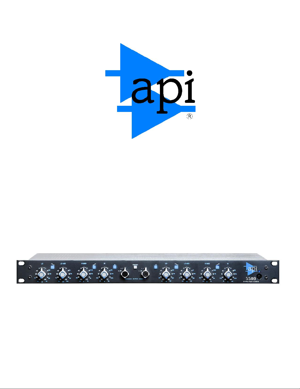
5500
DUAL EQUALIZER
API, 8301 Patuxent Range Road, Jessup, MD 20794 Tel: 301-776-7879
www.apiaudio.com
Page 2

THANK YOU FOR PURCHASING API’S 5500 DUAL EQUALIZER
Whether you’re seeking a truly superior analog sound, or simply want
to be part of the 40-year tradition of API excellence, we appreciate
your purchase. API takes great pride - and great care - in the hand
assembly of all our professional audio products. Above all, we
appreciate our loyal users, who have made the Company what it is
today.
Thank You for purchasing API's 5500 Dual Equalizer
Whether you re seeking a truly superior analog sound, or simply
want to be part of the nearly 40-year tradition of API excellence, we
appreciate your purchase.
API takes great pride - and great care - in the hand assembly of
all our professional audio products. Above all, we appreciate our loyal
users, who have made the Company what it is today.
Larry Droppa
President
PAGE 2
Page 3

AN OVERVIEW OF THE 5500 DUAL EQUALIZER
History of the API Equalizer
The lineage of the 5500 circuit can be traced back to the original 550 equalizer designed by
Saul Walker, the founder of Automated Processes Inc. That three band EQ was originally
used in the earliest API consoles built in the 1960s. Engineers were immediately captivated
by its fully reciprocal boost/cut characteristic and its proportional Q design, one of API’s many
industry firsts.
The sound of the 550, 550A, and 550B console equalizers was so highly prized by engineers
that many purchased API equalizers separately or took apart old consoles in order to install
the equalizers into a hand made chassis. This allowed them to have that same API console
sound available no matter where they were working. Today, API manufactures the six-space
Lunchbox and the 10-space VPR rack, making it easier for engineers to bring the API sound
to all of their recordings.
The 550 was designed as a console equalizer which, due to the architecture of the recording
console, uses an unbalanced input. Also, the ergonomics of a console dictates that controls
take up little space, sometimes limiting the number of functions that can be included in a
design. The 5500 is specifically designed to continue the tradition of API’s precision
equalization. It features a balanced input, a true straight-wire bypass, an integrated power
supply with noiseless muting, and a range control that expands its versatility to mastering
applications.
All Discrete Design
Like all API products, the 5500 contains no integrated circuits in its signal path. The gain
comes from two hand-built 2520 operational amplifiers in each channel and the balanced
input is handled by a 2510 discrete operational amplifier. Besides being a key component of
the API sound, the 2520 coupled with the API 2503 output transformer is capable of
delivering +30dBm before clipping. With this much headroom, it is unlikely that the 5500 can
be driven to distortion.
Proportional Q Circuitry
The Twin “T” topology is found in many equalizer circuits, but the legendary Saul Walker
included a novel Proportional Q section that makes it truly musical. Proportional Q works
by spreading the equalizer’s action over a broad bandwidth at low degrees of boost or cut.
This provides delicate shading and subtle coloring of the signal’s tone, without leaving the
impression that signal processing was applied. As the amplitude is advanced to more
extreme settings, the equalizer’s bandwidth narrows to provide the user with surgical
precision. This allows the equalizer to be useful in removing undesirable noises or radically
emphasizing an aspect of an instrument’s character, such as its attack.
The additional circuitry necessary to provide proportional Q is not included in most other
equalizers because it adds nothing to the spec sheet. Listening to musicality in the signal is
the only way to appreciate the benefits of the added cost and complexity required for
Proportional Q design.
PAGE 3
Page 4

Boost / Cut
Application
API Module Reference
+/- 2dB
Standard Equalization
550B
+/- 1dB
Higher Resolution Equalization
550D
+/- ½ dB
Mastering Equalization
550M
Fully Reciprocal Operation
Before the 1960s, few equalizers had the same characteristics in boost mode as in cut
mode. (In fact, many earlier designs did not have both boost and cut to begin with.)
Today, it is common for equalizers to be reciprocal, but again, Saul Walkers design is
special. When switching an API EQ from boost to cut, the exact same components are
used, reorganized around the amplifier for the appropriate function. This guarantees
100% reciprocity. The benefit becomes apparent when a track is re-equalized to remove
the previously applied equalization. The engineer can be confident that, because of the
5500s fully reciprocal design, a truly flat frequency response will be restored
Range Control
Each of the 5500s four band EQs features a separate Range Control, which allows the users
to choose from several API module boost and cut specifications, detailed below:
The range of the amplitude controls can be reduced to ½ or ¼ of their stated scale, with the
Q altered identically as before. Range Control provides a means of adjusting the tonal
balance with finer resolution in an even gentler manner. This should be especially useful for
complex program as contained in stems or submixes, and is ideally suited for mastering
purposes. The combination of reduced range equalization coupled with APIs characteristic
“warmth” can be useful in helping breathing life to the sterile sound often found in digital
recordings.
Power Mute and Bypass
The 5500 features a true hard-wire bypass. In this mode the output connector is wired
directly to the input. Shortly after power is first applied, or immediately after it is lost, a special
circuit forces this mode so
signal is never lost
BYP button lights orange in bypass mode whenever either the circuit or the operator put it
into bypass.
and
power thumps are never heard
. The
PAGE 4
Page 5
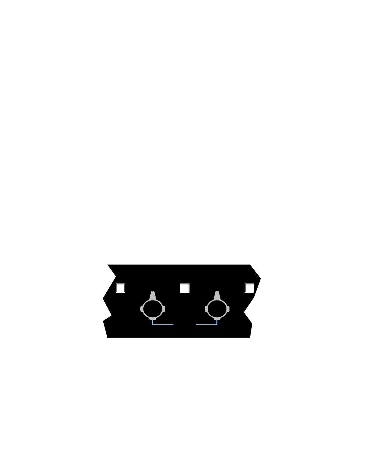
FRONT PANEL CONTROLS AND CONNECTIONS
RANGE and Amplitude Controls
The range control is a unique and powerful addition to the traditional 550 circuit. It is a formal
implementation of a popular factory modification of the 550 EQ.
In x1 mode, the equalizer behaves identically to the classic 550A and B. In .5 and .25 modes
the amplitude scale as shown on the front panel is reduced proportionally. True to the design
of the 550, the Q is reduced in an equivalent fashion, meaning that if 6dB of boost is selected
in the x1 range, you will get the same amount of boost and an identical shape of the EQ curve
by selecting 12dB in the .5 range. The classic subtlety of the 550 when used at low amplitude
settings is enhanced by the ability to perform micro-adjustments of tonal color. Mastering
engineers also prefer an equalizer that has exactly repeatable switch settings and the
capability of truly reciprocal operation, features that are common to all API equalizers.
BYPASS
When this is selected, the unit enters a true straight-wire bypass, the output is connected
directly to the input and there are no electronics in the signal path.
IN
When IN is selected, the equalizer is fully operational. When it is out there is no equalization
applied. It differs from BYPASS in that the electronics and output transformer are still in
the signal path.
BYPASSIN IN
20k
x .25
15k
x .5
x 1
x .25
x .5
x 1
12.5k
RANGE
PAGE 5
Page 6
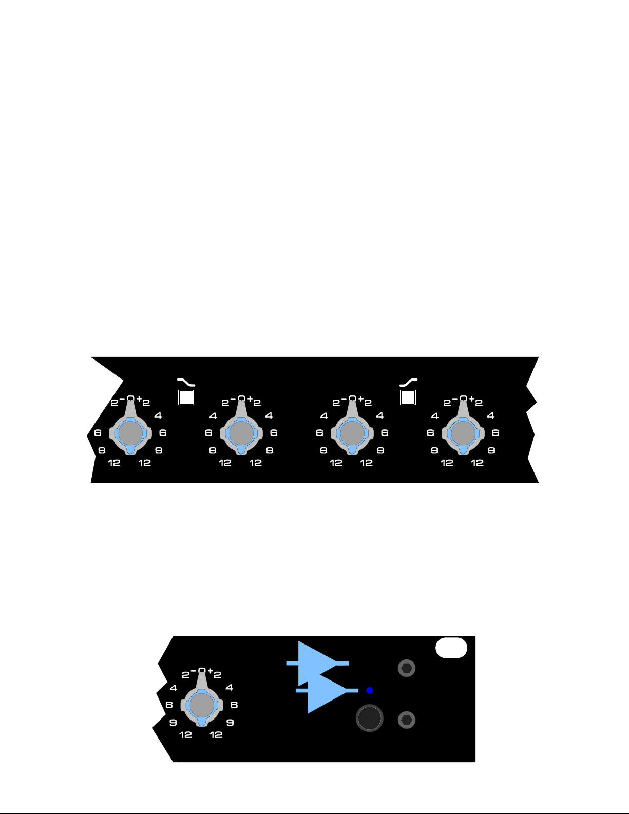
POWER
This power switch has a unique transient bypass capability. When powered down, the unit is
automatically forced into bypass, regardless of the BYPASS selection. Upon power-up there
is a delay which allows all the electronics to stabilize for approximately two seconds by
enforcing bypass mode. Also, if power is removed or lost for any reason, the bypass mode is
immediately invoked in order to maintain signal throughput without any interruption. The
BYPASS button’s light is orange whenever the unit is in bypass.
HI-MIDLO-MIDLO HI
PEAK/SHELF Switch
All equalizer sections have peaking (also called “bell” in the UK) response characteristics.
While the central frequency of that boost (or cut) is the one engraved on the panel, there is of
course amplitude variation that occurs to a lesser extent on nearby frequencies. This is termed
the Q where higher Q’s have less effect on adjacent frequencies. As mentioned before, the
API equalizers have a Proportional Q that gets larger as more amplitude change is selected.
On the highest and lowest bands there is an option to select shelving response. When in
shelving mode, the equalizer reaches the indicated amplitude at the indicated frequency
and remains with that amplitude change for all frequencies to the edge of the audio
spectrum. For frequencies towards the center of the spectrum the change is gradual, but the
slope differs slightly from the peaking mode. This can have important effects on the midrange
character of the sound, but that is not the typical reason to select shelving. The two principal
reasons for using a shelving response is either to eliminate noises like rumble that are outside
the frequency range of the desired sound, or to give a general “tilt” to the tonal balance
towards treble or bass. The API 5500 accomplishes both of these tasks without sounding
resonant.
12.5k
10k
8k
5k
2.5k
5k
7k
240
1k
500
700
800
1.5k
3k
400
300
200
40
100
50
75
150
180
20k
15k
12.5k
10k
HI
.
20k
2.5k
5k
7k
15k
12.5k
10k
api
5500
DUAL EQUALIZER
PAGE 6
Page 7
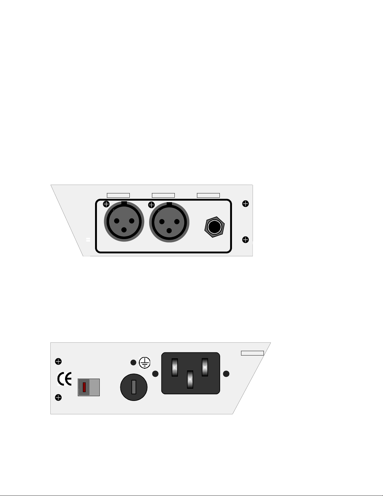
REAR PANEL CONTROLS AND CONNECTIONS
Balanced IN and OUT Connections
The input XLR is connected to an active balanced circuit. The output XLR is
driven from a transformer coupled output and can drive any load from 600 ohms
or greater to full output capability. The polarity is such that there is no change
from input to output, so it is suitable in studios using either pin 2 or pin 3 as the
“hot” connection.
There is a ¼ inch connector that interrupts any signal that is present on the
input XLR. It is balanced and can be driven from either balanced or
unbalanced sources. A positive signal on the tip will deliver a positive
signal on pin 2 of the output XLR. Using the ¼ inch input does not bypass
any internal circuitry and does not change gain or operating level.
Voltage Selection and Fuse
For line voltages from 100v to 120v, set the switch to 115v. The 230v position is
good for all line voltages from 200-240 volts. When set to the 115v position use a
500mA GMA fuse with Slo-Blo characteristics. At the 230v setting use a 250mA
Slo-Blo fuse. It is important to change the fuse when changing the supply
voltage.
XLR
PINS
1=G
2=+
3=+
1
INPUTOUTPUT
115v
5500
T 0.5A/0.25A 250V
115/230V~
50-60Hz
PAGE 7
Page 8

Transformer Option
There is a field upgradable option for a transformer-coupled input. The discrete balanced input
circuitry is bypassed using this transformer. It uses the highest quality line input transformer,
which can provide low distortion and wide bandwidth when fed from conventional professional
gear. Other brands of audio equipment will encounter clipping at around +24dBu, but another API
device could distort any input transformer since it is capable of an undistorted +30dBu output.
Since API equipment is capable of signal voltages that are typically twice as large as most
professional equipment, it is possible that the input transformer will experience some distortion in
the low frequencies when fed signals beyond +24dBu.
5500 SPECIFICATIONS
Input Impedance > 100Kohm balanced
Output Impedance < 75 ohm floating
Maximum output Level > +28dBm with 600 ohm or greater load
Frequency response < + 1dB from 10Hz to 30KHz
Distortion < 0.1% @+20dBu from 100Hz to 20KHz
Noise < -70dBu unweighted
Power Requirement 15 watts (130mA at 115v, 65mA at 230v)
PAGE 8
Page 9

Housekeeping:
Here is a great place to write down the serial number of your 5500 and your
purchase date, just in case you need that information someday in the future.
API 5500 serial number ________________
Purchase date: ____/_____/______
PAGE 9
 Loading...