

lunchbox® Rack Mount Conversion Manual 910-0859 REV. A - Page 1
Parts Included In The 920-0737 Kit:
(For 500-6B First Generation lunchboxes only)
(2) – 100-0946: Rack-ear support bracket
(2) – 100-0949: Rack-ear faceplate
(6) – 001-3002: Rack-ear faceplate screws
(2) – 001-0013: 6-32 bracket screws
(4) – 001-0025: 4-40 bracket screws
(8) – 002-0003: 6-32 Keps nut
(4) – 002-0002: 4-40 Keps nut
500-6B lunchbox
8 Slot lunchbox
This manual provides installation instructions for both versions of the API rack ears, 920-0859 and 920-0737. Most
lunchboxes use the 920-0859 rack ears kit. Only previous generation lunchboxes, which do not have “HC” listed in
the serial number and measure 12.4" X 5.25" X 7.25”, use the 920-0737 rack ears kit.
Tools Needed:
#1 Phillips head screwdriver
#2 Phillips head screwdriver
1/4” wrench
5/16” wrench
Parts Included In The 920-0859 Kit:
(For 500-6B “HC” and all 8 Slot lunchboxes)
(2) – 100-0946: Rack-ear support bracket
(2) – 100-0947: Rack-ear faceplate
(6) – 001-3002: Rack-ear faceplate screws
(2) – 001-0013: 6-32 bracket screws
(4) – 001-0025: 4-40 bracket screws
(8) – 002-0003: 6-32 Keps nut
(4) – 002-0002: 4-40 Keps nut
Directions:
1. Turn the lunchbox off and UNPLUG it completely from the power source. After ensuring that all
power indicators on the front panel are off, remove all of the installed 500 modules. Failure to
follow this step could cause personal and/or property damage.
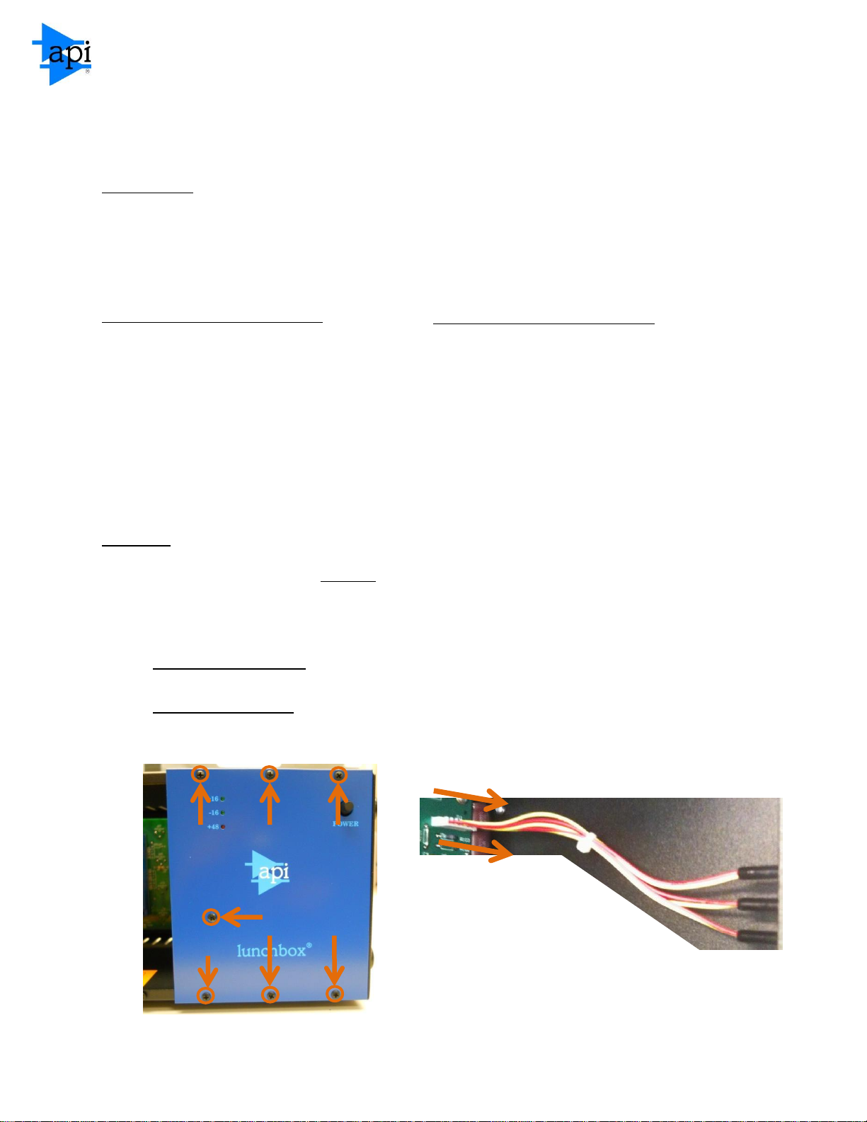
2. For 500-6B lunchboxes: Remove the blue front panel from the lunchbox by removing the
fastening screws with a #1 Phillips head screwdriver.
For 8 Slot lunchboxes: Disconnect the front panel LED power indicators by unplugging the wire
harness at location “J11” on the motherboard.
lunchbox® Rack Mount Conversion Manual 910-0859 REV. A - Page 2
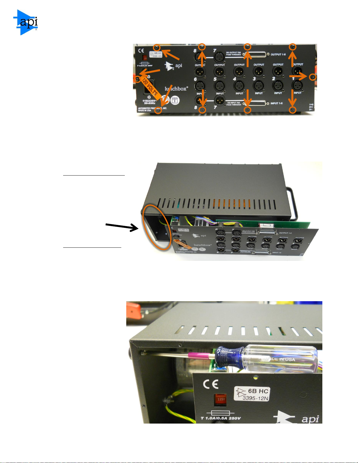
3. Turn the unit around
and loosen the rear
panel by removing the
ten fastening screws
with a #1 Phillips head
screwdriver. Be careful
not to lose the lock
washers that are
installed onto the
screws.
4. For 500-6B lunchboxes:
Slide the rear panel to the
right in order to allow
access to the four
mounting screws that
secure the side-mounted
rubber feet.
For 8 Slot lunchboxes:
Remove the rear panel
completely from the
lunchbox. Place it in a safe location.
5. Remove the four
side-mounted feet by
unscrewing them
from the chassis with
a #1 Phillips head
screwdriver.

lunchbox® Rack Mount Conversion Manual 910-0859 REV. A - Page 3
A A A&B
A&B
B B B
B A A
P/N: 100-0946
6. Install one rack ear support
bracket. Use the mounting
location of the side-mounted
feet removed in the previous
step. Secure the bracket using
four 001-0025 screws and four
002-0002 nuts. Install using a #1
Phillips head screwdriver and a
1/4” wrench. The screws go on
the inside of the lunchbox
chassis. Be sure to use the
correct set of holes on the rack
ear support bracket. Refer to
the proper mounting locations below:
A: 500-6B lunchbox Chassis Mounting
Locations
B: 8 Slot lunchbox Chassis Mounting Locations
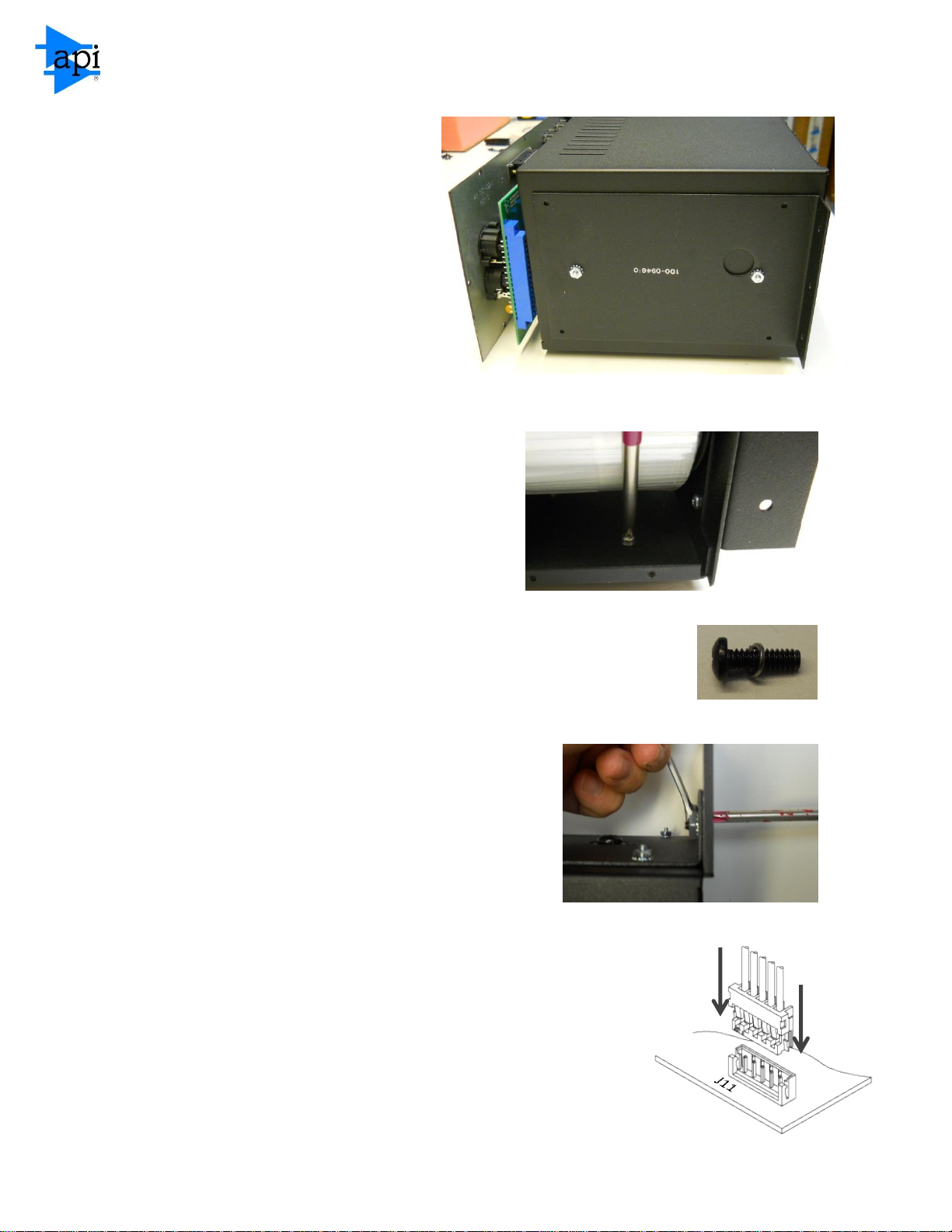
7. On the other side of the
lunchbox, locate the handle
mounting screws. On the 500-6B
lunchbox, you may have to
reposition the rear panel
assembly in order to gain access.
Remove both of these using a #2
Phillips head screwdriver.
lunchbox® Rack Mount Conversion Manual 910-0859 REV. A - Page 4
8. Install the final rack ear support
bracket. Use the mounting location
of the handle removed in the
previous step. Be sure to use the
correct set of holes on the rack ear
support bracket. For mounting
locations, refer to the diagram in
step 6. Secure the bracket using two
001-0013 screws and two 002-0003
nuts. Install using a #2 Phillips head
screwdriver and a 5/16” wrench. The
screws go on the inside of the lunchbox chassis.
9. Remove the remaining four bottom feet using a
#1 Phillips head screwdriver.
10. Reinstall the rear panel using the ten screws removed earlier. Remember
to reinstall the lock washer on each screw before installation. Use a #1
Phillips head screwdriver to tighten the screws.
11. Mount both rack ear faceplates using six 001-3002
screws and the remaining six 002-0003 nuts. Use a #2
Phillips head screwdriver and a 5/16” wrench.
12. On the 500-6B, reinstall the blue lunchbox faceplate by reinserting
the mounting screws. Be careful not to damage the LED indicators
when placing them through the panel. On the 8 Slot lunchbox, be
sure to reconnect the front panel LED power indicators to the
motherboard. To avoid damaging the lunchbox, be sure that the
connector is oriented properly before connecting. This completes
the rack ear installation process.
 Loading...