

SERIES
1/2009
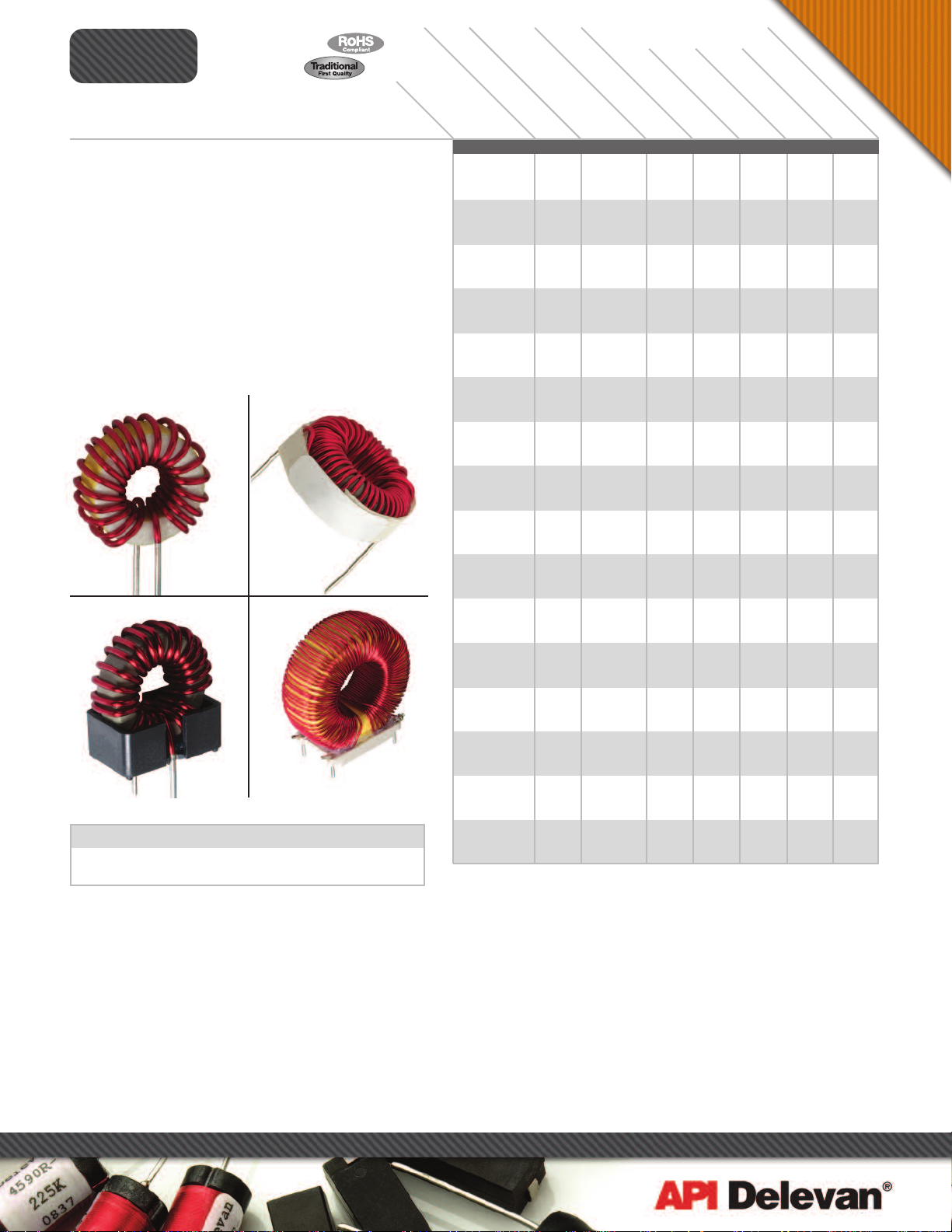
Power Toroids Horizontal or Vertical Mount
Inductance tested at 1 kHz, <10 gauss and 0 ADC
DC Resistance at 25°C
Rated Idc based on 40°C maximum rise from 25°C ambient with
0 Arms
Windings single layered to maximize operating frequency and
minimize board space
Self leads solder coated to within 0.050" of seating plane
Other values available on request
Packaging Bulk only
Mounting Standard mounting is self-lead radial per Figure “1”.
Optional mounting methods are self-leaded horizontal per Figure
“2” or vertical base mounted per Figures “3” and “4”.
IGURE
F
1
FIGURE
3
*Complete part # must include series # PLUS the dash #
refer to www.delevanfinishes.com
PT
IGURE
F
2
STANDARD
VERTICAL HORIZONTAL
FIGURE
4
VERTICAL
2-LEAD
For surface finish information,
VERTICAL
4-LEAD
PTxxxR
D
A
S
H
N
U
IN
D
. (
µ
H
)
±1
MB
E
R
*
PT5-530
PT5-700
PT5-800
PT5-1000
PT10-530
PT10-680
PT10-820
PT10-990
PT25-680
PT25-800
PT25-900
PT25-1000
PT50-780
PT50-900
PT50-1020
PT50-1320
PT75-900
PT75-980
PT75-1260
PT75-1550
PT100-1000
PT100-1100
PT100-1260
PT100-1550
PT150-1040
PT150-1250
PT150-1500
PT150-2050
PT250-1200
PT250-1500
PT250-1800
PT300-1200
PT300-1500
PT300-1750
PT400-1200
PT400-1500
PT400-1750
PT500-1450
PT500-1750
PT500-2000
PT750-1400
PT750-1700
PT750-2050
PT1000-1400
PT1000-1750
PT1000-2050
5
% @ 1
D
C
R
MA
XIMU
M (
O
k
H
H
z
PT SERIES POWER TOROIDS
5
0.015
5
0.012
5
0.010
5
0.008
10
0.020
10
0.015
10
0.010
10
0.008
25
0.035
25
0.025
25
0.020
25
0.014
50
0.050
50
0.030
50
0.025
50
0.020
75
0.060
75
0.040
75
0.035
75
0.025
100
0.080
100
0.050
100
0.035
100
0.028
150
0.100
150
0.060
150
0.050
150
0.040
250
0.130
250
0.080
250
0.055
300
0.150
300
0.100
300
0.075
400
0.250
400
0.180
400
0.110
500
0.220
500
0.160
500
0.090
750
0.350
750
0.280
750
0.150
1000
0.620
1000
0.420
1000
0.200
MOUNTING AVAILABLE
ED
ID
C
(
A
F
IG
MPS)
6.1
7.4
10.6
12.8
4.9
6.8
9.3
13.2
4.4
6.6
7.0
10.4
3.8
5.6
7.0
11.0
3.9
5.2
7.4
10.6
3.5
5.1
7.8
10.3
3.4
5.7
7.7
12.3
3.8
6.1
9.1
3.3
5.5
7.3
2.4
4.7
6.0
3.4
5.0
8.0
2.6
3.7
6.4
1.8
3.1
5.9
R
MS)
AT
. “1
VER
IG
VER
”
. “3
T
” 2
-
IC
A
L
•
•
•
•
•
•
•
•
•
•
•
•
•
•
•
•
•
•
•
•
•
•
•
•
•
•
•
•
•
•
•
•
•
•
•
•
•
•
•
•
•
•
•
•
•
•
F
IG. “4” 4-LEAD
VE
RTICAL
L
EA
D
•
•
•
•
•
•
•
•
•
•
•
•
•
•
•
•
•
•
•
•
•
•
•
•
•
•
•
•
•
•
•
•
•
•
•
•
H
”
ST
O
A
N
T
D
IC
A
A
L
F
R
IZ
F
O
IG
N
. “2
T
R
A
D
L
•
•
•
•
•
•
•
•
•
•
•
•
•
•
•
•
•
•
•
•
•
•
•
•
•
•
•
•
•
•
•
•
•
•
•
•
•
•
•
•
•
•
•
•
•
•
Power Inductors
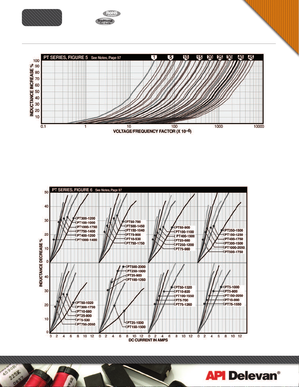
Notes to Figure 5 (Page 100) The PT Toroid Series inductance is specified at AC and DC signal levels which have no significant effect on the
permeability of the powdered iron toroidal core. Superimposed AC and DC voltages will change the permeability and therefore the inductance, under
operating conditions. Typically, DC currents will reduce the inductance, while AC signals will increase the inductance up to a point, before beginning to
decrease. Supporting information is provided, detailing the AC or DC effects upon each part. Saturation resulting from DC currents is specified with
waveform having less than a 1% ripple content. When considering the AC waveform, both the frequency and voltage level must be taken into account. As
an aid in defining what effect the alternating sine wave signal will have, the voltage/frequency factor curve can be used. To determine what change of
inductance can be expected at a given voltage level and frequency, simply divide the sinusoidal RMS voltage by the frequency. The voltage is in volts
and the frequency is in hertz. As an example, if using part number PT25-680 at a 1VRMS signal level, and a frequency of 25KHz, the voltage/frequency
factor is calculated to be: 1VRMS/25,000Hz = 40 x 10–6. Referring to the graph, a 39% increase in inductance would be expected.
Notes to Figure 6 (Page 100) Typical saturation effects as a function of DC flowing through the part. Data is representative of a DC waveform with
less than 1% ripple, and an AC waveform less than 10 gauss.
Note This information is intended to be used in assisting the designer in part selection. Each operating application may contain other variables which
must be considered in part selection; such as temperature effects, waveform distortion, etc.…
Delevan Sales/Engin eering staff is available to provide information as needed to fit each application.
270 Quaker Rd., East Aurora NY 14052 • Phone 716-652-3600 • Fax 716-652-4814 • E-mail: apisales@delevan.com • www.delevan.com

ELECTRICAL
1/2009
IN
D
.(
µ
N
U
MB
P
A
ER
PT5-530
PT5-700
PT5-800
PT5-1000
PT10-530
PT10-680
P
T10-820
PT10-990
PT25-680
PT25-800
PT25-900
PT25-1000
PT50-780
PT50-900
PT50-1020
PT50-1320
PT75-900
PT75-980
PT75-1260
PT75-1550
PT100-1000
PT100-1100
PT100-1260
PT100-1550
PT150-1040
PT150-1250
PT150-1500
PT150-2050
PT250-1200
PT250-1500
PT250-1800
PT300-1200
PT300-1500
PT300-1750
PT400-1200
PT400-1500
PT400-1750
PT500-1450
PT500-1750
PT500-2000
PT750-1400
PT750-1700
PT750-2050
PT1000-1400
PT1000-1750
PT1000-2050
Power Inductors
(
c
o
n
t
inu
e
d
D Min.
In
c
h
4.32
0.50
0.50
0.50
0.50
0.50
0.50
0.50
0.50
0.50
0.50
0.50
0.50
0.50
0.50
0.50
0.50
0.50
0.50
0.50
0.50
0.50
0.50
0.50
0.50
0.50
0.50
0.50
0.50
0.50
0.50
0.50
0.50
0.50
0.50
0.50
0.50
0.50
0.50
0.50
0.50
0.50
0.50
0.50
0.50
0.50
0.50
e
)
s
Nominal
E
mm
12.7
12.7
12.7
12.7
12.7
12.7
12.7
12.7
12.7
12.7
12.7
12.7
12.7
12.7
12.7
12.7
12.7
12.7
12.7
12.7
12.7
12.7
12.7
12.7
12.7
12.7
12.7
12.7
12.7
12.7
12.7
12.7
12.7
12.7
12.7
12.7
12.7
12.7
12.7
12.7
12.7
12.7
12.7
12.7
12.7
12.7
In
c
h
e
s
0.025
0.032
0.040
0.051
0.025
0.032
0.040
0.051
0.025
0.032
0.040
0.051
0.025
0.032
0.040
0.051
0.025
0.032
0.040
0.051
0.025
0.032
0.040
0.051
0.025
0.032
0.040
0.051
0.025
0.036
0.051
0.025
0.032
0.045
0.020
0.025
0.040
0.025
0.036
0.045
0.020
0.025
0.036
0.016
0.025
0.032
F Nominal
mm
0.64
0.450
0.81
0.600
1.02
0.720
1.30
0.950
0.64
0.450
0.81
0.600
1.02
0.720
1.30
0.950
0.64
0.580
0.81
0.700
1.02
0.820
1.30
0.950
0.64
0.680
0.81
0.790
1.02
0.920
1.30
1.220
0.64
0.770
0.81
0.890
1.02
1.200
1.30
1.500
0.64
0.880
0.81
0.890
1.02
1.200
1.30
1.500
0.64
0.880
0.81
1.160
1.02
1.420
1.30
2.000
0.64
1.200
0.91
1.450
1.30
1.750
0.64
1.200
0.81
1.400
1.14
1.750
0.51
1.150
0.64
1.400
1.02
1.750
0.64
1.400
0.91
1.700
1.14
2.000
0.51
1.400
0.64
1.660
0.91
2.000
0.41
1.360
0.64
1.660
0.81
2.000
In
c
h
m
e
s
m
11.43
15.24
18.30
24.13
11.43
15.24
18.30
24.13
14.73
17.78
20.83
24.13
17.27
20.07
23.37
30.99
19.56
22.61
30.48
38.10
22.35
22.61
30.48
38.10
22.35
29.46
36.07
50.80
30.48
36.83
44.45
30.48
35.56
44.45
29.21
35.56
44.45
35.56
43.18
50.80
35.56
42.16
50.80
34.54
42.16
50.80
PT
S
E
RIE
S
C
mm
Nominal
In
c
h
e
0.17
0.24
0.31
0.34
0.17
0.24
0.29
0.34
0.29
0.28
0.30
0.37
0.27
0.30
0.43
0.53
0.29
0.30
0.49
0.53
0.29
0.42
0.49
0.53
0.41
0.48
0.50
0.80
0.49
0.50
0.69
0.48
0.51
0.65
0.48
0.50
0.70
0.50
0.62
0.76
0.48
0.62
0.78
0.48
0.62
0.78
s
mm
6.10
7.87
8.64
4.32
6.10
7.37
8.64
7.37
7.11
7.62
9.40
6.86
7.62
10.92
13.46
7.37
7.62
12.45
13.46
7.37
10.67
12.45
13.46
10.41
12.19
12.70
20.32
12.45
12.70
17.53
12.19
12.95
16.51
12.19
12.70
17.78
12.70
15.75
19.30
12.19
15.75
19.81
12.19
15.75
19.81
HYSICAL PARAMETERS
P
H
)
±
1
5
%
@ 1k
R
T
R
MA
H
T
X. (
O
H
z
5
0.015
5
0.012
5
0.010
5
0.008
10
0.020
10
0.015
10
0.010
10
0.008
25
0.035
25
0.025
25
0.020
25
0.014
50
0.050
50
0.030
50
0.025
50
0.020
75
0.060
75
0.040
75
0.035
75
0.025
100
0.080
100
0.050
100
0.035
100
0.028
150
0.100
150
0.060
150
0.050
150
0.040
250
0.130
250
0.080
250
0.055
300
0.150
300
0.100
300
0.075
400
0.250
400
0.180
400
0.110
500
0.220
500
0.160
500
0.090
750
0.350
750
0.280
750
0.150
1000
0.620
1000
0.420
1000
0.200
ED
M
S)
ID
C
(
A
m
p
s
)
6.1
7.4
10.6
12.8
4.9
6.8
9.3
13.2
4.4
6.6
7.0
10.4
3.8
5.6
7.0
11.0
3.9
5.2
7.4
10.6
3.5
5.1
7.8
10.3
3.4
5.7
7.7
12.3
3.8
6.1
9.1
3.3
5.5
7.3
2.4
4.7
6.0
3.4
5.0
8.0
2.6
3.7
6.4
1.8
3.1
5.9
Max.
A
In
c
h
e
0.53
0.70
0.80
1.00
0.53
0.68
0.82
0.99
0.68
0.80
0.90
1.00
0.78
0.90
1.02
1.32
0.90
0.98
1.26
1.55
1.00
1.10
1.26
1.55
1.04
1.25
1.50
2.05
1.20
1.50
1.80
1.20
1.50
1.75
1.20
1.50
1.75
1.45
1.75
2.05
1.40
1.70
2.05
1.40
1.75
2.05
s
13.46
17.78
20.32
25.40
13.46
17.27
20.83
25.15
17.27
20.32
22.86
25.40
19.81
22.86
25.91
33.53
22.86
24.89
32.00
39.37
25.40
27.94
32.00
39.37
26.42
31.75
38.10
52.07
30.48
38.10
45.72
30.48
38.10
44.45
30.48
38.10
44.45
36.83
44.45
52.07
35.56
43.18
52.07
35.56
44.45
52.07
R
D
A
C
Power Toroids
Max.
B
In
c
m
h
e
m
s
SERIES PT IRON CORE
0.23
0.33
0.36
0.40
0.23
0.33
0.37
0.40
0.37
0.35
0.40
0.40
0.36
0.38
0.62
0.63
0.36
0.38
0.60
0.64
0.36
0.50
0.60
0.64
0.50
0.58
0.62
0.92
0.55
0.60
0.77
0.55
0.60
0.76
0.55
0.60
0.78
0.58
0.75
0.88
0.55
0.70
0.85
0.55
0.70
0.85
5.84
8.38
9.14
10.16
5.84
8.38
9.40
10.16
9.40
8.89
10.16
10.16
9.14
9.65
15.75
16.00
9.14
9.65
15.24
16.26
9.14
12.70
15.24
16.26
12.70
14.73
15.75
23.37
13.97
15.24
19.56
13.97
15.24
19.30
13.97
15.24
19.81
14.73
19.05
22.35
13.97
17.78
21.59
13.97
17.78
21.59
Note: Vertical configuration is standard; add suffix “HM” for horizontal mounting
FIGURE 1: STANDARD VERTICAL MOUNT FIGURE 2: HORIZONTAL MOUNT
270 Quaker Rd., East Aurora NY 14052 • Phone 716-652-3600 • Fax 716-652-4814 • E-mail: apisales@delevan.com • www.delevan.com

ELECTRICAL
1/2009
IN
D
.(
µ
H
N
U
MB
P
A
R
ER
T
T5-530-VM
P
T5-700-VM
P
PT5-800-VM
T10-530-VM
P
PT10-680-VM
T10-820-VM
P
T25-680-VM
P
PT25-800-VM
T25-900-VM
P
PT50-780-VM
T50-900-VM
P
T50-1020-VM
P
PT75-900-VM
T75-980-VM
P
PT75-1260-VM
T100-1000-VM
P
PT100-1100-VM
PT100-1260-VM
T150-1040-VM
P
PT150-1250-VM
T150-1500-VM
P
PT250-1200-VM
PT250-1500-VM
PT300-1200-VM
PT300-1500-VM
PT400-1200-VM
PT400-1500-VM
PT400-1750-VM
PT500-1450-VM
PT500-1750-VM
PT750-1400-VM
PT750-1700-VM
PT750-2050-VM
PT1000-1400-VM
PT1000-1750-VM
PT1000-2050-VM
Power Inductors
(
c
o
n
t
inu
e
d
D Typical
In
c
h
0.025
0.032
0.040
0.025
0.032
0.040
0.025
0.032
0.040
0.025
0.032
0.040
0.025
0.032
0.040
0.025
0.032
0.040
0.025
0.032
0.050
0.025
0.050
0.025
0.050
0.020
0.050
0.050
0.050
0.050
0.050
0.050
0.050
0.050
0.050
0.050
)
e
s
Max.
E
mm
0.63
0.81
1.02
0.63
0.81
1.02
0.63
0.81
1.02
0.63
0.81
1.02
0.63
0.81
1.02
0.63
0.81
1.02
0.63
0.81
1.27
0.63
1.27
0.63
1.27
0.51
1.27
1.27
1.27
1.27
1.27
1.27
1.27
1.27
1.27
1.27
In
c
h
e
s
0.640
0.810
0.910
0.640
0.790
0.930
0.790
0.910
1.010
0.890
1.110
1.130
1.010
1.090
1.390
1.130
1.230
1.390
1.170
1.380
1.630
1.330
1.630
1.330
1.630
1.330
1.630
1.880
1.580
1.880
1.530
1.830
2.180
1.530
1.980
2.180
F Typical
In
mm
16.26
0.290
20.57
23.11
0.415
16.26
0.290
20.07
0.325
23.62
0.415
20.07
0.325
23.11
0.415
25.65
0.475
22.61
0.415
28.19
0.415
28.70
0.625
25.65
27.69
0.475
35.31
0.625
28.70
0.475
31.24
0.475
35.31
0.625
29.72
0.475
35.05
0.625
41.40
0.900
33.78
0.625
41.40
0.900
33.78
0.625
41.40
0.900
33.78
0.625
41.40
0.900
47.75
1.200
40.13
0.900
47.75
1.200
38.86
0.900
46.48
1.200
55.37
1.200
38.86
0.900
50.29
1.200
55.37
1.200
c
h
e
s
0.325
0.475
mm
7.37
8.25
10.54
7.37
8.25
10.54
8.25
10.54
12.06
10.54
10.54
15.87
12.06
12.06
15.87
12.06
12.06
15.87
12.06
15.87
22.86
15.87
22.86
15.87
22.86
15.87
22.86
30.48
22.86
30.48
22.86
30.48
30.48
22.86
30.48
30.48
PT
S
E
RIE
S
In
mm
0.220
11.43
0.300
0.220
0.300
0.300
0.300
0.300
0.450
0.300
0.300
0.500
15.24
0.450
0.500
0.450
0.450
0.500
0.450
0.500
0.600
0.500
0.600
0.500
0.600
0.500
0.600
0.700
0.600
0.700
0.600
0.700
0.700
0.600
0.700
0.700
c
h
e
s
0.300
0.450
mm
5.59
7.62
7.62
5.59
7.62
7.62
7.62
7.62
11.43
7.62
7.62
12.70
11.43
11.43
12.70
11.43
11.43
12.70
11.43
12.70
15.24
12.70
15.24
12.70
15.24
12.70
15.24
17.78
15.24
17.78
15.24
17.78
17.78
15.24
17.78
17.78
HYSICAL PARAMETERS
P
)
±
1
5
%
@ 1k
MA
H
X. (
z
100
100
100
150
150
150
250
250
300
300
400
400
400
500
500
750
750
750
1000
1000
1000
ED
ID
C
(
O
H
M
S)
5
0.015
5
0.012
0.010
5
0.020
10
0.015
10
0.010
10
0.035
25
0.025
25
0.020
25
0.050
50
0.030
50
0.025
50
7
0.060
5
0.040
75
0.035
75
0.080
0.050
0.035
0.100
0.060
0.050
0.130
0.080
0.150
0.100
0.250
0.180
0.110
0.220
0.160
0.350
0.280
0.150
0.620
0.420
0.200
F
A
m
p
s
)
6.1
7.4
10.6
4.9
6.8
9.3
4.4
6.6
7.0
3.8
5.6
7.0
3.9
5.2
7.4
3.5
5.1
7.8
3.4
5.7
7.7
3.8
6.1
3.3
5.5
2.4
4.7
6.0
3.4
5.0
2.6
3.7
6.4
1.8
3.1
5.9
Max. B Max. C Typical
A
IG
In
U
c
R
h
E#
e
s
SERIES PT VERTICAL MOUNT IRON CORE
3
0.580
3
0.650
0.830
3
0.580
3
0.650
3
0.830
3
0.650
3
0.830
3
0.950
3
0.830
3
0.830
3
1.250
3
3
0.950
0.950
3
1.250
3
0.950
3
0.950
3
1.250
3
0.950
3
1.250
3
1.500
4
1.250
3
1.500
4
1.250
3
1.500
4
1.250
3
1.500
4
1.750
4
1.450
4
1.750
4
1.400
4
1.700
4
2.050
4
1.400
4
1.750
4
2.050
4
R
D
A
C
T
R
Power Toroids
In
c
m
h
e
m
s
14.73
0.340
16.51
0.450
21.08
0.450
14.73
0.340
16.51
0.450
21.08
0.450
16.51
0.450
21.08
0.450
24.13
0.600
21.08
0.450
21.08
0.450
31.75
0.700
24.13
0.600
24.13
0.600
31.75
0.700
24.13
0.600
24.13
0.600
31.75
0.700
24.13
0.600
31.75
0.700
38.10
0.800
31.75
0.700
38.10
0.800
31.75
0.700
38.10
0.800
31.75
0.700
38.10
0.800
44.45
0.900
36.83
0.800
44.45
0.900
35.56
0.800
43.18
0.900
52.07
0.900
35.56
0.800
44.45
0.900
52.07
0.900
8.64
11.43
8.64
11.43
11.43
11.43
11.43
15.24
11.43
11.43
17.78
15.24
17.78
15.24
15.24
17.78
15.24
17.78
20.32
17.78
20.32
17.78
20.32
17.78
20.32
22.86
20.32
22.86
20.32
22.86
22.86
20.32
22.86
22.86
FIGURE 3: 2-LEAD VERTICAL BASE MOUNT FIGURE 4: 4-LEAD VERTICAL BASE MOUNT
270 Quaker Rd., East Aurora NY 14052 • Phone 716-652-3600 • Fax 716-652-4814 • E-mail: apisales@delevan.com • www.delevan.com
Power Inductors
1/2009
SERIES
Power Toroids Horizontal or Vertical Mount
KEY TO FIGURE 5 CURVE NUMBERS Graphs apply to all mounting styles. For more detailed graphs, contact factory.
1) PT5-530
2) PT10-530
3) PT5-700
4) PT5-800
5) PT10-680
6) PT5-1000
PT
7) PT10-820
8) PT10-990
9) PT25-680
10) PT25-800
11) PT25-900
12) PT25-1000
13) PT50-780
14) PT50-900
15) PT75-900
16) PT75-980
17) PT50-1020
18) PT100-1000
19) PT100-1100
20) PT50-1320
21) PT150-1040
22) PT75-1260
23) PT100-1260
24) PT75-1550
25) PT100-1550
26) PT150-1250
27) PT150-1500
28) PT250-1200
29) PT300-1200
30) PT250-1500
31) PT400-1200
32) PT300-1500
33) PT400-1500
34) PT250-1800
35) PT150-2050
36) PT300-1750
37) PT500-1450
38) PT400-1750
39) PT750-1400
40) PT500-1750
41) PT1000-1400
42) PT750-1750
PTxxxR
43) PT500-2000
44) PT1000-1750
45) PT750-2050
46) PT1000-2050
For more detailed graphs, contact factory
270 Quaker Rd., East Aurora NY 14052 • Phone 716-652-3600 • Fax 716-652-4814 • E-mail: apisales@delevan.com • www.delevan.com
 Loading...