

Page 1

Page 2

TABLE OF CONTENTS
Assembly Diagram (Page 2)
Parts List (Page 2)
Detailed Assembly Instructions For Cutting Jig (Page 3)
Detailed Assembly Instructions For Platform (Page 6)
Operating Instructions (Page 8)
Maintenance (Page 11)
Replacement Parts and Service (Page 11)
Safety (Page 11)
1
Page 3

A
B
D
C
L M E H G H F
K
J
M
N
I
ASSEMBLY DIAGRAM
PARTS LIST
Part Description Quantity ID
A Main base 1 MB-01
B Sliding post 1 SP-01
C Clamping bar 1 CP-01
D Guide 1 GR-01
E Cutting jig (front component) 1 CF-01
F Cutting jig (rear component) 1 CR-01
G Spacers (four thicknesses: 1mm, 2mm, 3mm, 4mm) 4 pairs SSS-01
H Blades Varies BLSS-01
I Bolt (plastic, 2 inches long) 1 BOSP-01
J Bolts (metal, 0.75 inches long) 2 BOG-01
K Bolts (metal, 3 inches long) 2 BOC-01
L Knurled nuts 2 KN-01
M Washers (small) Varies WS-01
N Washers (large) Varies WL-01
2
Page 4

DETAILED ASSEMBLY INSTRUCTIONS
Beveled side
Assembly of the Cutting Jig
1. Insert the two bolts (part K) through the holes of the cutting jig (rear component; part F).
2. Slide the blade (part H) through the bolts and place it against the cutting jig.
The orientation of the blade is critical.
Sharp edge of
blade and
notched side
of cutting jig
should be on
the same side.
3. Select a pair of spacers (part G) with the same thickness and slide them through the bolts. The cartilage
slice obtained using the device will have a thickness equal to the thickness of the spacer selected.
of blade
should be
facing down
and towards
the cutting
jig.
The spacers should be positioned
so that they do not block the
center of the cutter.
3
Page 5

4. Slide the blade (part H) through the bolts. The bevel of this blade should face away from the spacers
Bevel side of
under it.
blade should be
facing up and
away from the
spacers under it.
5. Slide the cutting jig (front component; part E) through the bolts.
6. Slide the small washers (part M) through the bolts.
4
Page 6

other.
7. Screw the two nuts (part L) onto the bolts in order to secure the cutting jig together. Firmly tighten by
hand.
8. Illustration of cutting jig after complete assembly:
Important Note:
If assembled correctly,
the beveled sides of the
two blades should be
facing away from each
5
Page 7
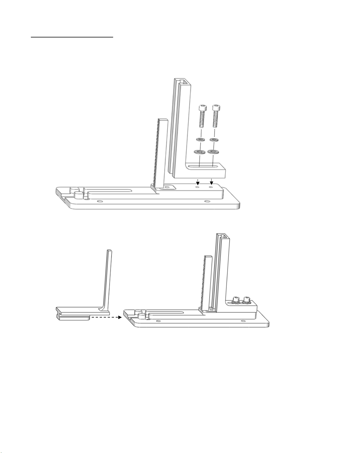
Assembly of the Platform
1. Place the main base (part A) on a flat surface. Slide the small washers (part M) onto the two bolts (part
J). Then slide the larger washers (part N) onto the bolts. Slide the bolts through the guide (part D) and
screw them into the main base. The bolts should be loose enough so that the guide can slide back and
forth.
2. Slide the sliding post (part B) into the main base.
6
Page 8

3. Partially screw the bolt (part I) into the clamping bar (part C); several rotations of the bolt is sufficient.
Then, place the clamping bar into the inset of the main base.
1
2
4. Illustration of platform after complete assembly:
7
Page 9

OPERATING INSTRUCTIONS
The clamping bar
1. Place the costal cartilage between the two posts.
2. Tighten the horizontal bolt that goes through the clamping bar in order to compress the cartilage
between the posts. Compress the cartilage to flatten any curvature and to secure it tightly in place.
may need to be
pressed down to
hold it in place
while tightening
the bolt.
8
Page 10

1
Top view:
3. Slide the cutting jig through the guide until it rests on top of the cartilage. With the bolts of the guide
loosened, position the guide so the blades of the cutting jig are between the posts and at the center of
the cartilage. Once the cutting jig is properly positioned, secure the guide by tightening the two bolts.
The bolts may be tightened using the supplied wrench, but be careful not to damage the device by
excessive tightening.
Ensure that the blades are
centered and that the
cartilage will fit through the
opening of the cutting jig.
3
2
4. With a steady downward force, push the cutting jig through the cartilage.
It is recommended to push
down on rear component of
the cutting jig.
9
Page 11

2
3
5. Once the blade has reached the bottom and the cartilage is cut, loosen the horizontal bolt that is
attached to the clamping bar and loosen the bolts going through the guide. Then, remove the cutting jig
and cartilage.
1
10
Page 12

 Loading...