

Page 1
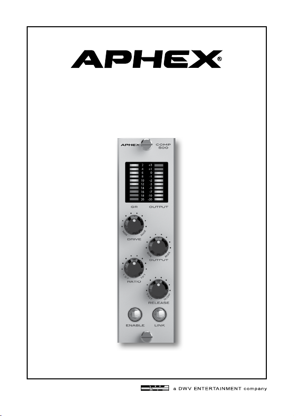
COMP 500
OPTICAL COMPRESSOR
500 SERIES MODULE
Owner’s Manual
®
Page 2
SAFETY DECLARATIONS
T
SAFETY DECLARATIONS
CAUTION: For continued protection against risk of fire, replace
only with the same type and rating of fuse.
ATTENTION: pour une protection continue contre les risques
d’incendie, ne remplacer qu’avec la même valeur et même type de
fusible.
WARNING: Do not place objects containing liquid on this unit as
it is not designed to protect against spillage. Do not expose this
unit to dripping or splashing of liquids as the unit is not designed
to protect against these occurrences.
WARNING: This unit must be connected to a mains socket outlet
with a protective earthing connection.
WARNING: The COMP 500 has been tested and meets the FCC,
CE and European Union rules, regulations, and guidelines for use.
Do not attempt to modify or change the COMP 500, as this could
void the regulatory compliance, which would place you at risk of
losing your authority to operate the COMP 500.
WARNING: Do not place objects on top of this unit if they weigh
more than 10 pounds.
Page 2
This equipment has been tested and found to comply with the limits
for a Class B digital device, pursuant to part 15 of the FCC rules.
These limits are designed to provide reasonable protection against
harmful interference in a residential installation. This equipment
generates, uses and can radiate radio frequency energy and, if not
installed and used in accordance with the instructions, may cause
harmful interference to radio communications. However, there is
no guarantee that interference will not occur in a particular installation. If this equipment does cause harmful interference to radio
or television reception, which can be determined by turning the
equipment off and on, the user is encouraged to try to correct the
interference by one or more of the following measures.
1. Reorient or relocate the receiving antenna.
2. Increase the separation between the equipment and receiver.
3. Connect the equipment into an outlet on a circuit different from
that to which the receiver is connected.
4. Consult the dealer or an experienced radio/TV technician for help.
Page 3
Page 3
TABLE OF CONTENTS
1.0 INSTALLATION 5
2.0 INTRODUCTION 6
3.0 CONTROLS AND INDICATORS 6
3.1 Drive Control 6
3.2 Ratio Control 7
3.3 Gain Reduction Meter 7
3.4 Release Control 7
3.5 Output Level Meter 8
3.6 Enable Button 8
3.7 Link Button 8
4.0 COMPRESSION 9
5.0 OPTICAL COMPRESSION 10
6.0 SERVICE & WARRANTY 11
6.1 Limited Warranty 11
6.2 Service Information 12
7.0 SPECIFICATIONS 12
1.0 INSTALLATION
1. Turn off and unplug your 500 series rack frame. Inspect the
card slot you intend to use to make sure that it is clean and free
of any debris.
2. Before removing your COMP 500 from its box, discharge any
static electricity buildup you may have by touching your 500
series rack.
3. Pull your COMP 500 module out of its box and carefully slide
it into place in the designated opening. Sight down the back of
the module (use a flashlight if necessary) and ensure the card
edge connector is aligned to seat into the card slot of the frame.
4. Firmly and evenly push the COMP 500 module into place
until it is positively seated in the card slot.
5. Use the 2 thumb screws in the module to mount the COMP
500 front panel to the 500 series rack. These screws have a
pretty tight fit; please be careful not to cross thread.
6. Plug your 500 series rack back into the AC source and power
up your rack. Your COMP 500 will automatically power up with
your 500 series rack.
Page 4
Page 5
Page 4

2.0 INTRODUCTION
The COMP 500 module is an optical compressor. It features an electronically balanced input and uses a Jensen JT-11DL nickel output
balancing transformer. The optocoupler was designed to be as fast
as possible and is produced exclusively for Aphex. The COMP 500
also features stereo linking.
3.2 RATIO CONTROL
The Ratio control determines how hard the
input signal is compressed. It has a range of
1.5:1 to 10:1. This means that with the knob
set fully clockwise, for every 10dB of input
signal only 1dB of signal is sent to the output.
Page 6
• Transparency in the behavior of the optical
element.
• Flexibility of being able to control the
release time from a leveling amp behavior
to a compression behavior.
• Character of the Jensen output transformer.
• The combination of these features makes
the COMP 500 unique.
3.0 CONTROLS & INDICATORS
3.1 DRIVE CONTROL
The Drive control determines the amount
of input signal sent to the compressor. The
COMP 500 has a maximum input level of
+27dB. Turning this knob clockwise will
result in more gain reduction. However, the
total amount of gain reduction is determined
by the Ratio control.
3.3 GAIN REDUCTION METER
The 10-segment Gain Reduction meter provides visual feedback as to the amount of
gain reduction measured in dB. The example
above would register about 12dB of gain
reduction.
3.4 RELEASE CONTROL
The Release control determines the amount
of time it takes for the audio signal to return
to normal levels after the signal is no longer
being compressed. Use a slower setting for a
leveling affect when inserting the COMP 500
on a buss. A faster setting would be more
appropriate for compressing a dynamic signal
like a vocal or kick drum.
Page 7
Page 5

3.5 OUTPUT LEVEL CONTROL
This knob controls the overall output level of
the module and drives the output level meter.
3.6 OUTPUT LEVEL METER
This 10-sement meter provides visual feedback
of the output level of the device. The meter
range if from -20dBu to +3dBu.
3.7 ENABLE BUTTON
This is essentially a bypass for the device. When
the module is active this button will light up.
The light will go off when the unit is bypassed.
3.8 LINK BUTTON
Two COMP 500 modules can be stereo linked
when they are installed as adjacent odd/even
pairs. Slot 1 & 2, 3 & 4, etc. This follows API’s
protocol for linking. Frames made by other
manufacturers may be different. Check your
frames’ manual for details on stereo linking.
Engaging the LINK button on both modules
will cause the module with the most gain reduction to be the master and the same amount of
gain reduction will be applied to the adjacent
module. This feature helps maintain a wide
stereo image. The Drive and Output parameters must be set so that the gain structure is
the same on both modules for this function to
work properly. Pin 6 of the modules are used
for this function.
4.0 COMPRESSION
It you are reading this, congratulations! Learning more about
what compression is and how it benefits you will ensure
you get the best results from your COMP 500 module.
COMPRESSORS-WHAT THEY DO
The basic idea is that a wide range of input levels is automatically
“compressed” into a smaller range of output levels. After compression, sounds that were low in volume are higher in volume
and sounds that were high in volume are made lower in volume.
This results in more consistent volume levels that sit “just right”
in a mix without some parts being too loud with other parts too
soft.
PUNCH AND SUSTAIN
When a compressor reduces the volume of a loud sound, it does
so in way that is unique to each type of compressor. The time
it takes for this volume reduction to occur is called “attack”. An
attack that is too fast can change the natural character of an
instrument while too slow can lose the benefits of compression.
The COMP 500s interactive attack adapts to the input signal,
controlling volume without changing character and enhancing
punch while retaining articulation.
Typically, compression creates more sustain by raising the level
as the sound decays. This is more or less apparent, depending on
the input signal.
Page 8
Page 9
Page 6

5.0 OPTICAL COMPRESSION-WHAT IS IT?
There are many ways to create a circuit that controls the gain
reduction of a compressor. Each method has its own characteristics and all have produced popular compressors over the years.
One of the most popular types is the optical compressor.
An optical compressor is created from the combination of a light
sensitive resistor called a photocell, and a light source such as a
small bulb or LED. Devices called optocouplers combine a photocell and light source inside a light-proof package. The photocell
increases its resistance when input level increases the intensity
of the light - that increased resistance provides the compression.
While attack is the time it takes for compression to occur, “release”
is the time it takes for the signal to return to normal. Photocells
have a characteristic called “memory” that makes such a compressor interactive. When just a few brief attacks have been
experienced, the photocell recovers quite fast, bringing back the
level more quickly. However, after repeated and constant attacking, the photocell builds up a memory of the light pulses and
recovers more gradually. This helps to smooth out the compression and preserve the character of the sound.
6.0 SERVICE & WARRANTY
6.1 LIMITED WARRANTY
PERIOD
One year from date of purchase.
SCOPE
All defects in workmanship and materials. The following are not covered:
a. Voltage conversions.
b. Units on which the serial number has been defaced, modified, or removed
c. Damage or deterioration:
1. Resulting from installation and/or removal of the unit.
2. Resulting from accident, misuse, abuse, neglect, unauthorized
product modification or failure to follow instructions contained
in the User’s Manual.
3. Resulting from repair or attempted repair by anyone not
authorized by Aphex.
4. Occurring fr om shipping (claims must be presented to shipper).
WHO IS PROTECTED
This warranty will be enforceable by the original purchaser and by any subsequent
owner(s) during the warranty period, so long as a copy of the original Bill of
Sale is submitted whenever warranty service is required.
WHAT WE WILL PAY FOR
We will pay for all labor and material expenses for covered items. We will pay
return shipping charges if the repairs are covered by the warranty.
LIMITATION OF WARRANTY
No warranty is made, either expressed or implied, as to the merchantability
and fitness for any particular purpose. Any and all warranties are limited to
the duration of the warranty stated above.
EXCLUSION OF CERTAIN DAMAGES
Aphexs’ liability for any defective unit is limited to the repair or replacement
of said unit, at our option, and shall not include damages of any other kind,
whether incidental, consequential, or otherwise.
Some States do not allow limitations on how long an implied warranty lasts
and/or do not allow the exclusion or limitation of incidental or consequential
damages, so the above limitations and exclusions may not apply to you.
This warranty gives you specific legal rights, and you may also have other
rights which vary from State to State.
Page 10
Page 11
Page 7

6.2 SERVICE INFORMATION
If it becomes necessary to return this unit for repair, you must first contact
Aphex for a Return Authorization (RMA number), which will need to be
included with your shipment for proper identification. If available, repack
this unit in its original carton and packing material. Otherwise, pack the
equipment in a strong carton containing at least 2 inches of padding on
all sides. Be sure the unit cannot shift around inside the carton. Include a
letter explaining the symptoms and/or defect(s). Be sure to reference the
RMA number in your letter and mark the RMA number on the outside of
the carton. If you believe the problem should be covered under the terms of
the warranty, you must also include proof of purchase. Insure your shipment
and send it to:
APHEX
3500 N. San Fernando Blvd. Burbank, CA. 91505 USA
PH: 818.767.2929 FAX: 818.767.2641
7.0 SPECIFICATIONS
OPERATING LEVEL
Switch Setting:
INPUT
Impedance:
Max Input Level (comp off):
Max Input Level (comp on):
OUTPUT
Impedance:
Nominal Operating Level:
Maximum Level:
Level Meter Peak:
AUDIO
Frequency Response:
POWER
Current draw:
Page 12
+4dBu
Transformerless, active balanced
Type:
40kohm balanced, 20kohm unbalanced
>40dB @ 60Hz
CMRR:
N/A - true bypass
>26dBu
Transformer balanced
Type:
100 ohm nominal
+4dBu
+26dBu
+18 dBu
+0.1/-1.0dB <10Hz to 45kHz
<0.003% @ +4dBu input
THD:
min ratio, no compression)
<0.05% @ +10dBu input (Drive/Output mid,
THD:
max ratio, ~6dB compression)
60 mA
(Drive/Output mid,
CONNECTOR PINOUT
1 CHASSIS GROUND
2 OUTPUT + (+4 LEVEL)
3 (unused)
4 OUTPUT - (+4 LEVEL)
5 COMMON
6 LINK
7 (unused)
8 INPUT- (+4 LEVEL)
9 (unused)
10 INPUT+ (+4 LEVEL)
11 (unused)
12 +16VDC
13 POWER SUPPLY COMMON
14 -16VDC
15 (unused)
3500 N San Fernando Blvd. Burbank, CA 91505 USA
PH: 818.767.2929 FAX: 818.767.2641
www.APHEX.com
Page 13
 Loading...