

Page 1
I N T E R FACES
M O D E L 1 4 1 / 1 4 2 / 1 4 4
O W N E R ’ S G U I D E
Page 2
Model 141 ADAT to Analog Converter
INSTRUCTION-ANUAL
A MESSAGE FROM THE PRESIDENT
Safety Declarations
This equipment has been tested and found to comply with the limits for a Class A digital device pursuant to
The user is cautioned that changes and modifications made to the equipment without approval of the manufacturer could
Model 142 Analog to ADAT Converter
Model 144 AES/ADAT Bi-directional Converter
1.0 Introduction
The Aphex Models 141, 142 and 144 were developed as interfaces between the Aphex Anaconda
digital snake system and other devices. Each model was designed to do its job without any extra
unnecessary bells or whistles. While they each fulll that design specication, each model is an
excellent, useful product in it own right.
Since the I/O of the Anaconda is ADAT, there is an ADAT connection in each model. The ADAT eight
channel format has been a standard in the audio industry for years. It is a reliable, mature, cost
effective technology albeit with limitations. The prime limitation is the distance that ADAT audio can
be safely transmitted through ‘Lightpipe’ ber. Some claim that it could be as far as 30 feet, but our
experience shows that there can be signicant audible artifacts at 20 feet. We strongly recommend
that the distance be as short as possible, preferably less than 10 feet (3 meters).
The other limitation is that its maximum sample rate is 48kHz for eight channel operation. There is
a technology called S-Mux that doubles the maximum frequency but halves the channel count. We
have elected to stay with the sample rate of 48kHz in the Model 142, but Models 141 and 144 can
work at 44.1 or 48kHz.
There are many other products on the market that do similar functions. But none as simply or as
well or as cost effectively, as these units. You will enjoy many years of excellent uninterrupted
performance.
Page 1
Page 3
Model 141 ADAT to Analog Converter
Model 142 Analog to ADAT Converter
Model 144 AES/ADAT Bi-directional Converter
2.0 Installation and Interfacing
Rack Installation
All three models are 1.75” high (1RU), 8.25” wide and 7.25” deep. They can be rack mounted by
using the Aphex accessory # 44-008SA rack kit. One kit can be used to mount a pair of units or a
single unit in 1RU. Follow the instructions included with the rack kit for assembly.
Make sure that there is sufcient airow around the units. Do not mount them directly on top of
equipment that generates excessive heat or near equipment that generates large magnetic hum
elds.
AC connections
All the models have internal power supplies that are preset to a specic operating voltage. Make sure
that the unit is set to the proper voltage for your area before connecting to AC power.
Audio connections
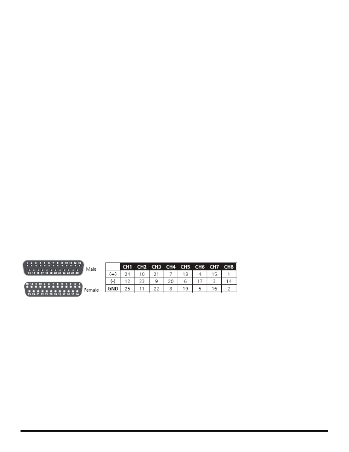
Analog audio connections in the Models 141 and 142 are through TASCAM analog standard 25 pin
D-Sub. Both input on the Model 142 and output on the Model 141 are female D-Sub connectors on
the chassis. D-Sub connections are as follows:
Balanced inputs
The analog audio input stages in the Model 142 are balanced. They can be driven by either a
balanced or an unbalanced input. If unbalanced, connect the “Hot” to the “+” pin on the input
connector. Connect ground to the “G” pin and “ - “ pin. Maximum input level, balanced or unbalanced
is +24dBu.
Balanced outputs
The analog audio outputs of the Model 141 are impedance balanced. This is a true balanced circuit,
however audio signals appear only on the “+” connector pins. If driving a balanced input connect the
output pins “+” and “-” to the appropriate input connections. It is recommended that the ground be
connected only at the receiving end. If driving an unbalanced input connect “+” to the “hot” input and
connect “G” to the ground connection at the receiving end. You can leave the “-” unconnected or it
can be tied to ground. Maximum output level is +24dBu.
Page 2
Page 4

Owner’s Manual
Model 141 ADAT to Analog Converter
Model 142 Analog to ADAT Converter
Model 144 AES/ADAT Bi-directional Converter
ADAT connections
ADAT connections use a standard TOSLINK optical transmitter and receiver on the Model 144, a
receiver on the Model 141 and a transmitter on the Model 142. Keep ADAT connections as short as
possible.
AES connections
AES connections use Aphex standard 15 pin D-Sub. The AES output from the Model 144 is female
and the AES input to the Model 144 is male. The connections are as follows:
Word clock
The Anaconda system is designed to work at 48kHz sampling frequency only. In order to achieve its
unmatched performance, the clock must be within +/-5Hz of 48kHz. That is why the Anaconda has its
own super stable and accurate clock generator and distribution system.
The Model 142 has a word clock input on a standard BNC with an internal 75Ω terminating resistor.
If there is no word clock connected, the clock will be approximately 48kHz, but not exactly. It is highly
recommended that a 48kHz word clock be connected to the Model 142 even if the unit is not part of
an Anaconda system.
The Model 141 needs no clock as it converts whatever is on the ADAT input to analog. It can accept
44.1kHz or 48kHz.
The Model 144 has no separate clock input. However, the same word clock (either 44.1kHz or 48kHz)
must be used for all the AES sources. Also, AES input channels 1 and 2 must be connected to the
Model 144 in order for the clock to be derived for the ADAT output.
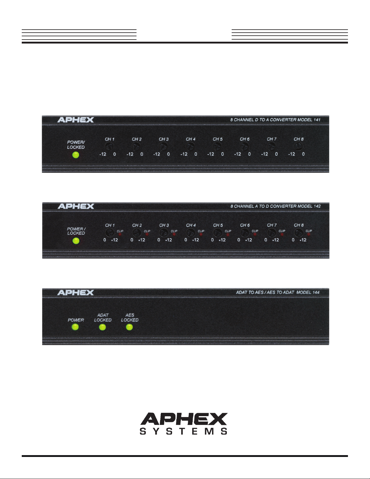
LED Indicators
Models 141 and 142 have a single bi-color red/green LED labeled “Power/Locked”. The LED will
be red when power is supplied but without any ADAT connected to the Model 141 or word clock
connected to the Model 142. When there is a valid ADAT signal (either at 44.1kHz or 48kHz)
connection to the Model 141 the LED will turn green.
Page 3
4
Page 5

Model 141 ADAT to Analog Converter
Model 142 Analog to ADAT Converter
Model 144 AES/ADAT Bi-directional Converter
When there is a valid word clock connection to the Model 142 (at 48 kHz only ), the LED will turn
green.There is a red LED next to each input trimmer on Model 142. It illuminates when the input
signal exceeds +24dBu to indicate clipping on that channel.
There are three green LED’s on the Model 144. When power is applied the “Power” LED is lit.
When a valid ADAT signal is present (either at 44.1kHz or at 48kHz) the “ADAT LOCKED” LED is lit.
Wen
When there is AES input (there must be the connection to AES Channel 1,2 at either 44.1 or 48kHz)
the “AES LOCKED” LED is lit.
If there are any red LED’s illuminated it indicates a problem somewhere in the system.
Note: The ADAT to AES circuit is completely independent from the AES to ADAT circuit.
Analog Audio Level
+24dBu is the maximum analog audio input level into the Model 142 and the maximum analog audio
output level from the Model 141. This level corresponds to 0dBfs (full scale) in the digital domain.
There is a trimmer for each analog audio input to the Model 142 that adjusts the gain by 12dB.If the
unit is being fed by a professional level device (0Vu = +4dBu) the gain trimmer should be set to “0”. If
the Model 142 is being fed by a consumer level device (0Vu = -10dBV) the trimmer should be set to
“+12”.
There is a trimmer for each analog audio output of the Model 141 that adjusts the gain by 12 dB. If
the unit is feeding a professional level device (0Vu = + 4 dBu ) then the trimmer should be set to “ 0 “ .
If the Model 141 is feeding a consummer level device ( 0 Vu = - 10 dBV ) the trimmer should be set
to “- 12“.
Page 4
Page 6

Model 141 ADAT to Analog Converter
Model 142 Analog to ADAT Converter
Model 144 AES/ADAT Bi-directional Converter
3.0 specication
Specications
Model 141 142 144
Max Input 0dBfs +24dBu 0dBfs
Max Output +24dBu 0dBfs 0dBfs
THD+Noise -100dB -100dB N/A
Dynamic Range 114dB 114dB N/A
Trim Range 12dB 12dB N/A
Jitter <1nsec <1nsec <1nsec
Power Consumption 10 Watts
Frequency Response 20Hz 20kHz ±0.5dB N/A
Size 1RU 1/2 Rack Width 1.75”H x 8.25”W x 7.25”D
Weight 3.5lbs (1.6kg) (44.5mm x 209.5mm x 184.2mm)
Connectors Toslink Toslink Toslink (2)
25 Pin D-sub Tascam Format 25 Pin D-sub Tascam Format 15 Pin D-sub Aphex Format (2)
BNC Word Clock
All specications are subject to change without notice.
Page 5
COPYRIGHT 2008 by Aphex Systems, LTD . All rights reserved . All Aphex products are trademarks or registered trademarks of Aphex Systems , LTD .
Other brand and product names are Trademarks of their respective holders.
Page 7

Model 141 ADAT to Analog Converter
MODEL 141
8 CHANNEL
D TO A CONVERTER
APHEX SYSTEMS
AC LINE
10 WATTS
Model 142 Analog to ADAT Converter
AC LINE
10 WATTS
SUN VALLEY, CA
MADE IN USA
From ADAT source
MODEL 142
8 CHANNEL
A TO D CONVERTER
APHEX SYSTEMS
SUN VALLEY, CA
MADE IN USA
To ANALOG input
WORD
CLOCK
INPUT
ADAT
INPUT
ADAT
OUTPUT
ANALOG OUTPUTS
CH2
CH4 CH6
NC
-
G
CH1
G
+
-
G
+
CH3
-
-
G
+
G
-
G
+
+
CH5
ANALOG INPUTS
CH2
CH4 CH6
NC
-
G
CH1
G
+
-
G
+
CH3
-
-
G
+
G
-
G
+
+
CH5
CHAN
POS(+) NEG(-) GND
24
12
CH8
-
G
+
-
G
+
CH7
CH8
-
G
+
-
G
+
CH7
1
10
2
+
-
+
-
21
3
7
4
18
5
4
6
15
7
1
8
PIN 13 NC - NO CONNECTION
CHAN
POS(+) NEG(-) GND
24
1
10
2
21
3
7
4
18
5
4
6
15
7
1
8
PIN 13 NC - NO CONNECTION
25
23
11
9
22
20
8
6
19
17
5
3
16
14
2
12
25
23
11
9
22
20
8
6
19
17
5
3
16
14
2
From WORD CLOCK
source
To ADAT input
From ANALOG source
Model 144 AES/ADAT Bi-directional Converter
MODEL 144
APHEX SYSTEMS
AC LINE
10 WATTS
From ADAT source
SUN VALLEY, CA
MADE IN USA
ADAT TO AES
AES TO ADAT
To AES input
ADAT
INPUT
AES OUTPUTS
CH7,8
CH5,6 CH3,4
-
-
+
G
G G G
CH1,2
-
+
-
+
+
From AES source *
* Channel 1,2 must
be connected
AES INPUTS
CH1,2
CH3,4 CH5,6
-
+
+
G
G G G
-
CH7,8
-
+
+
To ADAT input
-
ADAT
OUTPUT
Page 6
Page 8

Aphex Systems Ltd.
USA
C
HANNEL
11068 Randall St.
Sun Valley CA 91352 , USA
Tel: (818) 767 - 2929
Fax: (818) 767- 2641
Web: www.aphex.com
Email: sales@aphex.com
 Loading...