

Page 1

APG
Resistive Chain Continuous Level Probes
User Manual
Series RPE and RPX
Doc #9002671
R
Part #200582
Rev C, 10/2020
Page 2

Table of Contents
Introduction ................................................................................................................ iii
Warranty and Warranty Restrictions .................................................................... iv
Chapter 1: Specications and Options.....................................................................1
Dimensions ....................................................................................................................................1-2
Specications ............................................................................................................................... 3-4
Model Number Congurators ........................................................................................................ 5
Wire Color and Terminal Tables ................................................................................................... 6
Chapter 2: Installation and Removal Procedures and Notes ..............................7
Tools Needed .....................................................................................................................................7
Physical Installation Notes ...........................................................................................................7
Installation Notes ............................................................................................................................7
Mounting Instructions ................................................................................................................... 8
Electrical Installation .....................................................................................................................8
Removal Instructions ..................................................................................................................... 8
Chapter 3: Maintenance .............................................................................................9
General Care ...................................................................................................................................... 9
Offset and Span Calibration ...........................................................................................................9
Repair and Returns ........................................................................................................................ 10
Chapter 4: Hazardous Location Installation and Certication ........................ 11
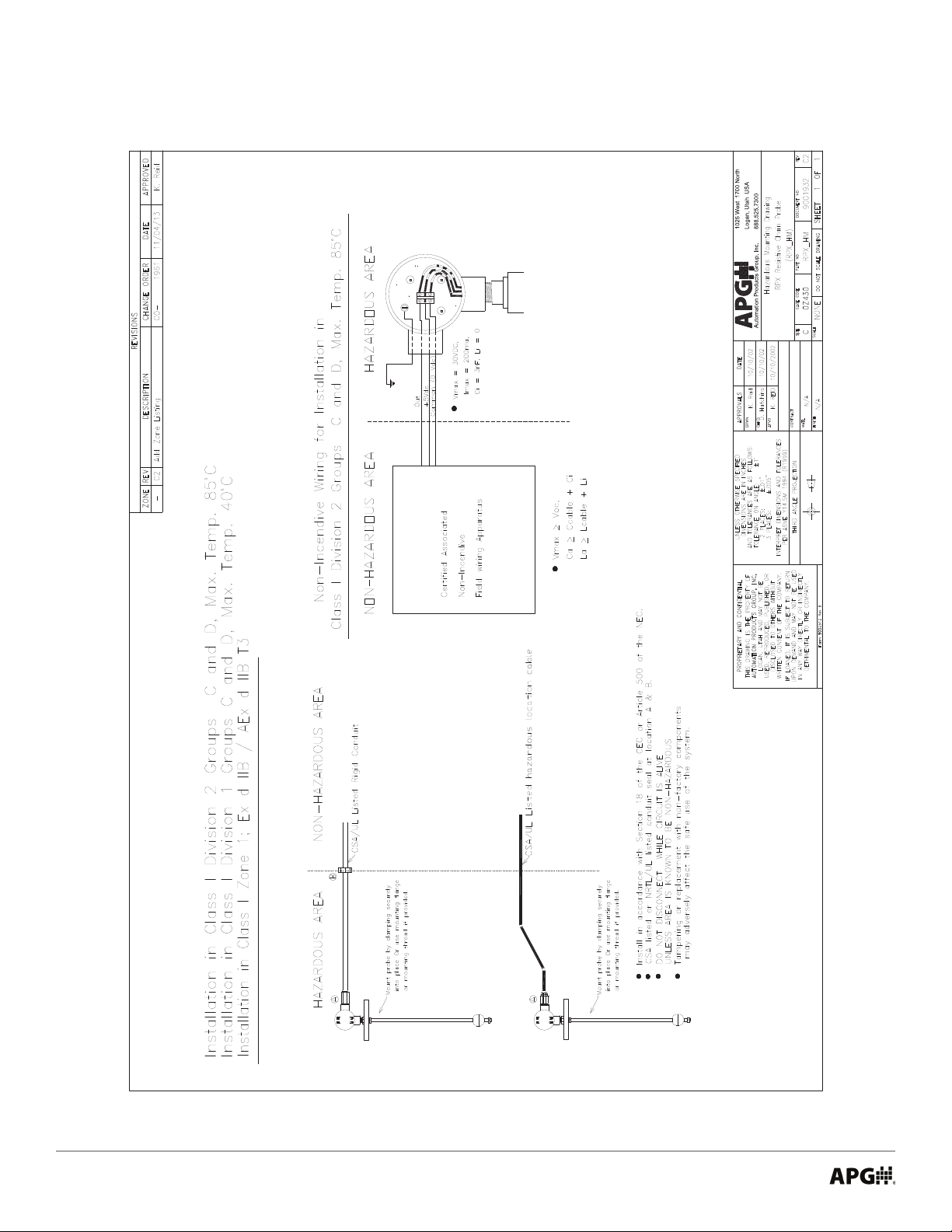
Hazardous Installation Drawing For RPX ............................................................................11
IS
Hazardous Mounting Drawing RPX ........................................................................................... 12
CSA Certicate of Compliance ............................................................................................... 13-17
ii
Tel: 1/888/525-7300 • Fax: 1/435/753-7490 • www.apgsensors.com • [email protected]
Page 3

Introduction
237484
Thank you for purchasing a RP Resistive Chain Continuous Level Probe from APG. We appreciate your
business! Please take a few minutes to familiarize yourself with your RPE or RPX and this manual.
The RP resistive probes contain reed switches in a 1/2” Ø stainless steel stem and a permanent magnet
in a oat. As the oat rises or falls with the level of the liquid, the magnet inside the oat acts on the
corresponding reed switches inside the stem changing the output of the probe. The RPX carries explosion
proof, intrinsically safe, and non-incendive hazardous location approvals.
Reading your label
Every APG instrument comes with a label that includes the instrument’s model number, part number, and
serial number. Please ensure that the part number on your label matches your order.
RPX Electrical ratings
Class I Division 1, Groups C, and D T3
Ta 40°C
Rated: 5 - 24 VDC, 100 mA, or 12 - 24 VDC, 4-20 mA
C
Ex d, IIB T3
Class I Zone1, AEx, IIB T3
Ta 40°C
Rated: 5 - 24 VDC, 100 mA, or 12 - 24 VDC, 4-20 mA
US
Class I Division 2, Groups C, and D T3
Ta 85°C
Rated: 5 - 24 VDC, 100 mA, or 12 - 24 VDC, 4-20 mA
Class I Division 2, Groups C, and D T3
Ta 85°C
Field wiring is non-incendive when installed per drawing 9001932
Rated: 5 - 15 VDC, 100 mA, or 12 - 24 VDC, 4-20 mA
Class I Division 1, Groups C, and D T3C
Max Ta 85°C
Intrinsically Safe when installed per drawing 9001930 with following entity parameters:
V
Rated: loop-powered 24 VDC, 4-20 mA converter module
= 30 V, I
max
= 130 mA, Ci = 3 nF, Li = 0 μH
max
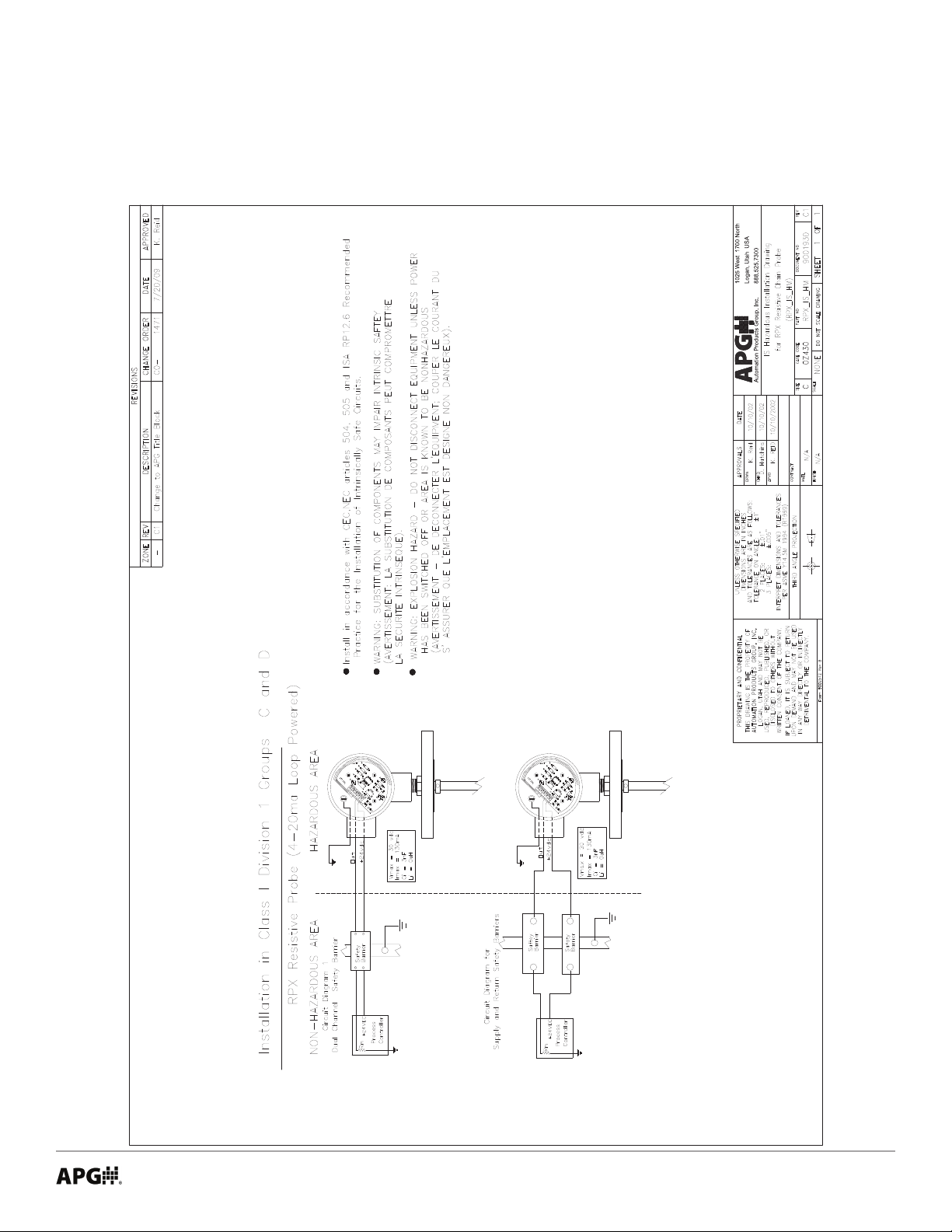
IMPORTANT: Your RPX MUST be installed according to drawing 9001930 (IS Hazard-
ous Installation Drawing For RPX) or 9001932 (Hazardous Mounting Drawing RPX) to meet
listed approvals. Faulty installation will invalidate all safety approvals and ratings.
Tel: 1/888/525-7300 • Fax: 1/435/753-7490 • www.apgsensors.com • [email protected]
iii
Page 4
DANGER: OPEN CIRCUIT BEFORE REMOVING COVER or KEEP COVER TIGHT WHILE CIRCUITS ARE ALIVE;
AVERTISSEMENT -- COUPER LE COURANT AVANT D’ENLEVER LE COUVERCLE, ou GARDER LE COUVERCLE
FERME TANT QUE LES CIRCUITS SONT SOUS TENSION.
IMPORTANT: SEAL SHALL BE INSTALLED WITHIN 50 mm OF THE ENCLOSURE;
IMPORTANT -- UNSCELLEMENT DOIT ETRE INSTALLE A MOINS DE 50 mm DU BOITIER.
DANGER: EXPLOSION HAZARD-DO NOT DISCONNECT WHILE CIRCUIT IS LIVE UNLESS AREA IS KNOWN TO
BE NON-HAZARDOUS;
AVERTISSEMENT -- RISQUE D’EXPLOSION. NE PAS DEBRANCHER TANT QUE LE CIRCUIT EST SOUS TENSION, A
MOINS QU’IL NE S’AGISSE D’UN EMPLACEMENT NON DANGEREUX.
WARNING: SUBSTITUTION OF COMPONENTS MAY IMPAIR INTRINSIC SAFETY;
AVERTISSEMENT -- LA SUBSTITUTION DE COMPOSANTS PEUT COMPROMETTRE LA SECURITE INTRINSEQUE.
Warranty and Warranty Restrictions
This product is covered by APG’s warranty to be free from defects in material and workmanship under
normal use and service of the product for 24 months. For a full explanation of our Warranty, please visit
https://www.apgsensors.com/about-us/terms-conditions. Contact Technical Support to receive a Return
Material Authorization before shipping your product back.
Scan the QR code below to read the full explanation of our Warranty on your tablet or smartphone.
iv
Tel: 1/888/525-7300 • Fax: 1/435/753-7490 • www.apgsensors.com • [email protected]
Page 5
Chapter 1: Specications and Options
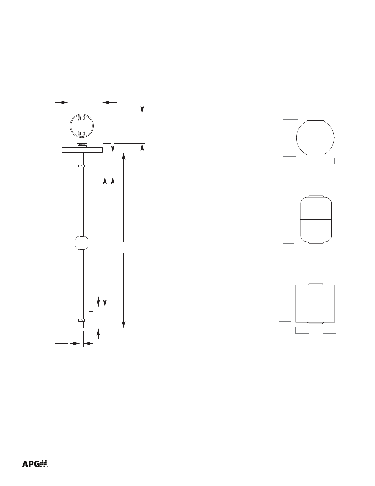
• Dimensions
RPX or
RPE with Large Aluminum Housing
4.5”
114 mm
114 mm
S1
M
L
RPE/RPX Floats
Float E
4.5”
2.01”
51 mm
2.01”
51 mm
Float F
2.17”
55 mm
1.48”
38 mm
S2
0.5”
13 mm
Legend
L = Total Stem Length
M = Measured Length
S1 = Top Deadband (1.75” / 44.5 mm)
S2 = Bottom Deadband (1.75” / 44.5 mm)
L = M + S1 + S2 M = L - S1 - S2
Maximum Stem Length:
RPX: 96” / 2440 mm
Float G
1.77”
45 mm
1.89”
48 mm
Tel: 1/888/525-7300 • Fax: 1/435/753-7490 • www.apgsensors.com • [email protected]
1
Page 6
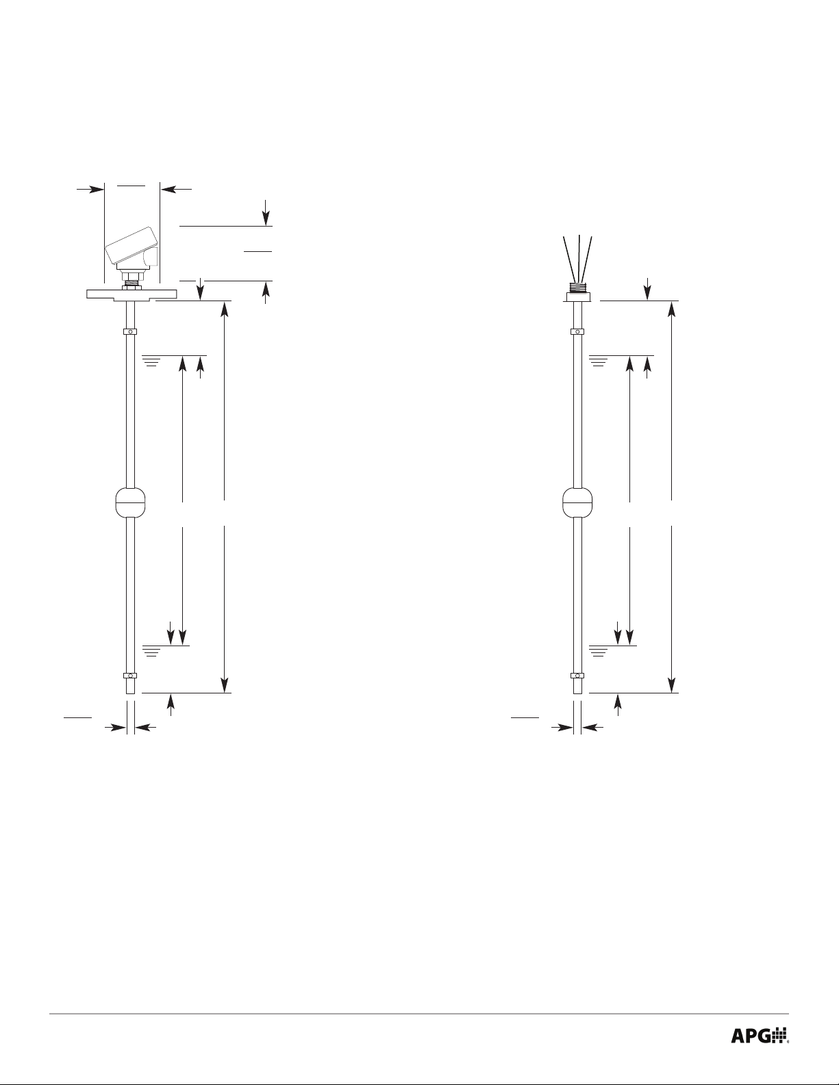
RPE with Small Housing
Nylon or Aluminum
3.5”
89 mm
4.0”
102 mm
RPE with No Housing
0.5”
13 mm
S2
S1
M
L
0.5”
13 mm
S2
S1
M
L
Legend
L = Total Stem Length
M = Measured Length
S1 = Top Deadband (1.75” / 44.5 mm)
S2 = Bottom Deadband (1.75” / 44.5 mm)
L = M + S1 + S2 M = L - S1 - S2
Maximum Stem Length:
RPE: 153” / 3890 mm
2
Tel: 1/888/525-7300 • Fax: 1/435/753-7490 • www.apgsensors.com • [email protected]
Page 7

• Specications
RPX
Performance
Resolution ±0.25 in. (6.4 mm)
Accuracy ±0.12 in. (3 mm)
Environmental
Temperature See Chart Below
Maximum pressure 72.5 PSI (5 bar)
Enclosure Protection NEMA 4 & 7, IP65
Electrical
Output 4-20 mA; Resistive
Typical Current (Resistive Output) I = VDC supply / (45 Ω * Length in inches)
Internet Connectivity via RST-5003; 4-20 mA output only
Materials of Construction
Stem 316L Stainless Steel
Floats 316L Stainless Steel, or Buna
Housing Die Cast Aluminum
Mechanical
Conduit connection 3/4” NPTM
Maximum stem length 96 inches / 8 feet / 2440 mm
Float Specic Gravity 0.39, 0.57, or 0.65
RPX Outputs with Temperature and Power Requirements for Hazardous Locations
Output
A - 4-20 mA,
Hazardous
R -Resistive,
Hazardous
I - 4-20 mA,
Intrinsically
Safe
Intrinsically Safe
Class I, Div. 1
Groups C & D T3C
--
--
Loop powered 24
VDC;
Install per dwg
9001930
-40° - 85° C / (-40° -
185°F)
Class I, Div. 1 Groups C & D T3;
Class I, Zone 1 Ex/AEx d, IIB T3
12-24 VDC Supply
-40° - 40° C / (-40° - 104°F)
5-24 VDC Supply, 100 mA max
-40° - 40° C / (-40° - 104°F)
Explosion Proof
-- -- --
Non-incendive
Class I, Div. 2
Groups C & D T3
12-24 VDC Supply;
Install per dwg 9001932
-40° - 85° C / (-40° - 185°F)
5-15 VDC Supply, 100 mA
max
Install per dwg 9001932
-40° - 85° C / (-40° - 185°F)
Class I, Div. 2
Groups C & D, T3.
12-24 VDC Supply
-40° - 85° C / (-40° - 185°F)
5-15 VDC Supply, 100 mA
max
-40° - 85° C / (-40° - 185°F)
Tel: 1/888/525-7300 • Fax: 1/435/753-7490 • www.apgsensors.com • [email protected]
3
Page 8

RPE
Performance
Resolution ±0.25 in. (6.4 mm)
Accuracy ±0.12 in. (3 mm)
Environmental
Temperature -40 - 85°C / -40 - 185°F
Maximum Pressure 72.5 PSI (5 bar)
Enclosure Protection
Large Aluminum NEMA 4 & 7, IP65
Small Nylon IP65
Small Aluminum NEMA 4X, IP68
Electrical
Output 4-20 mA; Resistive
Voltage and Current Ratings
Resistive 5 - 24 VDC, 100 mA (max)
4-20 mA 12 - 24 VDC, 4-20 mA
Typical Current (Resistive Output) I = VDC supply / (45 Ω * Length in inches)
Hookup wire 22 AWG
Internet Connectivity via RST-5003; 4-20 mA output only
Masterials of Construction
Materials
Stem 316L Stainless Steel
Floats 316L Stainless Steel, or Buna
Housing
Large Cast Aluminum
Small Nylon
Small Aluminum
Mechanical
Conduit connection
Large Aluminum 3/4” NPT
Small Nylon 1/2” NPT
Small Aluminum 3/4” NPT
Maximum stem length 153 inches / 12.75 feet / 3890 mm
Float Specic Gravity 0.39, 0.57, or 0.65
4
Tel: 1/888/525-7300 • Fax: 1/435/753-7490 • www.apgsensors.com • [email protected]
Page 9

• Model Number Congurator
Model Number: RPX - _____ - _____ _____ - __S6__ - _____ - _____
A B C D E F
A. Output
□ A Hazardous, 4-20 mA output
□ R Hazardous, resistive output
□ I Intrinsic safety, 4-20 mA output
B. Mounting Type, Option, and Size
□ F Flat Face ANSI 150# Flange (size=1.5, 2, 2.5, 3, 4)
□ R Raised Face ANSI 150# Flange (size=1.5, 2, 2.5, 3, 4)
□ S Triclamp (size=2, 2.5, 3, 4)
□ P Externally-mounted NPT Plug 150#
(size=1.5†, 2, 2.5, 3, 4)
□ N None
D. Stem Material
□ S6 316L Stainless Steel
E. Float Type
□
E 316L SS 2.01 in. (53 mm) Round; 0.57 SG
□ F 316L SS 2.17h x 1.48w in. (55h x 38w mm); 0.65 SG
□ G Buna 1.77h x 1.89w in. (45h x 48w mm); 0.39 SG
F. Stem Length in Inches
□ __
C. Mounting Connection
□ W Welded (xed)
□ S Slide with Compression Fitting
†Note: Size 1.5 NPT Externally-mounted (P1.5) requires oat F.
Model Number: RPE - _____ - _____ _____ - __S6__ - _____ - _____ - _____ _____
A B C D E F G H
Min. 11 in. - Max 96 in.
A. Output
□ A 4-20 mA output†
□ R Resistive output
B. Mounting Type, Option, and Size
□ F Flat Face ANSI 150# Flange (size=1.5, 2, 2.5, 3, 4)
□ R Raised Face ANSI 150# Flange (size=1.5, 2, 2.5, 3, 4)
□ S Triclamp (size=2, 2.5, 3, 4)
□ P Externally-mounted NPT Plug 150#
(size=1.5††, 2, 2.5, 3, 4)
□ I Internally-mounted NPT Plug 150#†††
(size=0.25, 0.375, 0.5, 0.75, 1, 1.25, 1.5)
□ N None
C. Mounting Connection
□ W Welded (xed)
□ S Slide with Compression Fitting
D. Stem Material
□ S6 316L Stainless Steel
†Note: Output A 4-20 mA requires Housing A Large Aluminum.
††Note: Size 1.5 NPT Externally-mounted (P1.5) requires oat F.
†††Note: Mounting Type I Internally-mounted NPT Plug requires
Housing W Hookup Wire and Output R Resistive.
E. Float Type
□
E 316L SS 2.01 in. (53 mm) Round; 0.57 SG
□ F 316L SS 2.17h x 1.48w in. (55h x 38w mm); 0.65 SG
□ G Buna 1.77h x 1.89w in. (45h x 48w mm); 0.39 SG
F. Stem Length in Inches
□ __
Min. 11 in. - Max 153 in.
G. Housing, Cable Entry Size
□ A
□ B
□ C
□ W Hookup wire (no housing)
Large Aluminum, 3/4” NPT
Small Nylon, 1/2” NPT
Small Aluminum, 3/4” NPT
H. Hookup Wire Length
□ 12 12 in.
□ 24 24 in.
□ __
Specify length in inches
Tel: 1/888/525-7300 • Fax: 1/435/753-7490 • www.apgsensors.com • [email protected]
5
Page 10
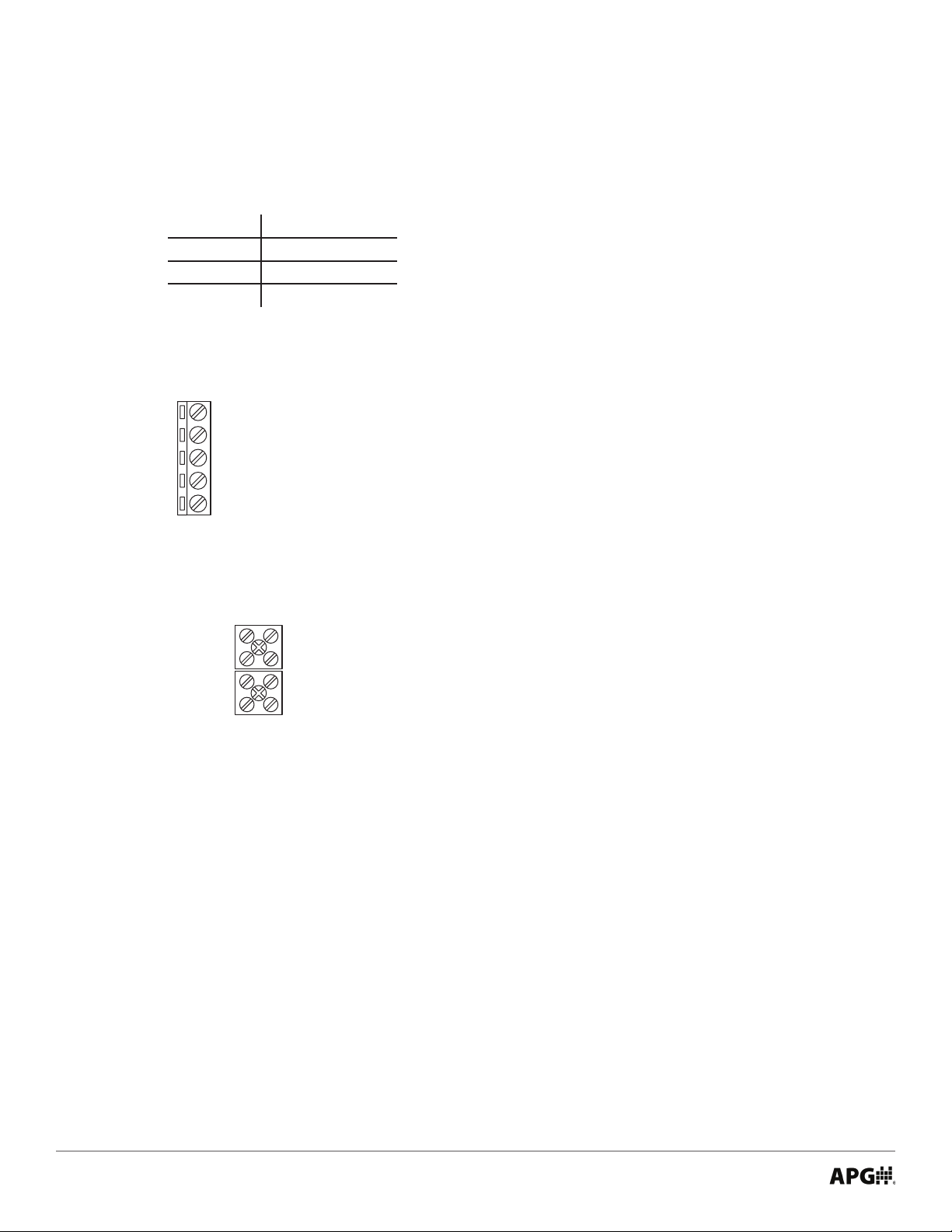
• Wire Color and Terminal Tables
Wire Colors For RPE-R with Hookup Wires
Wire Resistive Output
Red +24 VDC
Black DC Ground
White Voltage Out
Terminals for RPX-A, RPX-I, and RPE-A (4-20 mA Output)
Black (Internal)
White (Internal)
Red (Internal)
Output
+24 VDC
Terminals for RPE-R with Housing and RPX-R (Resistive Output)
Output
Ground
VDC Supply
White (Internal)
Black (Internal)
Red (Internal)
6
Tel: 1/888/525-7300 • Fax: 1/435/753-7490 • www.apgsensors.com • [email protected]
Page 11
Chapter 2: Installation and Removal Procedures and Notes
• Tools Needed
• Wrench sized appropriately for your RPE’s or RPX’s mounting
• Wrench sized appropriately for conduit connections
• Thread tape or sealant compound for threaded connections
• Physical Installation Notes
The RPE or RPX should be installed in an area--indoors or outdoors--which meets the following conditions:
• IEC-664-1 Conductive Pollution Degree 2
• IEC 61010-1 Measurement Category II
• Altitude up to 2000 meters (6560 feet)
• Relative humidity up to 100%
• DC power supply
• Ambient temperature between -40°C and 85°C (-40°F to +185°F)
• No chemicals corrosive to stainless steel (such as NH3, SO2, Cl2 etc.)
• Ample space for maintenance and inspection
Additionally, locate the probe:
• Away from strong magnetic elds, such as those produced by motors, transformers, solenoid valves,
etc.
• Away from excessive vibration.
• In a medium free from metallic substances and other foreign matter.
• Installation Notes
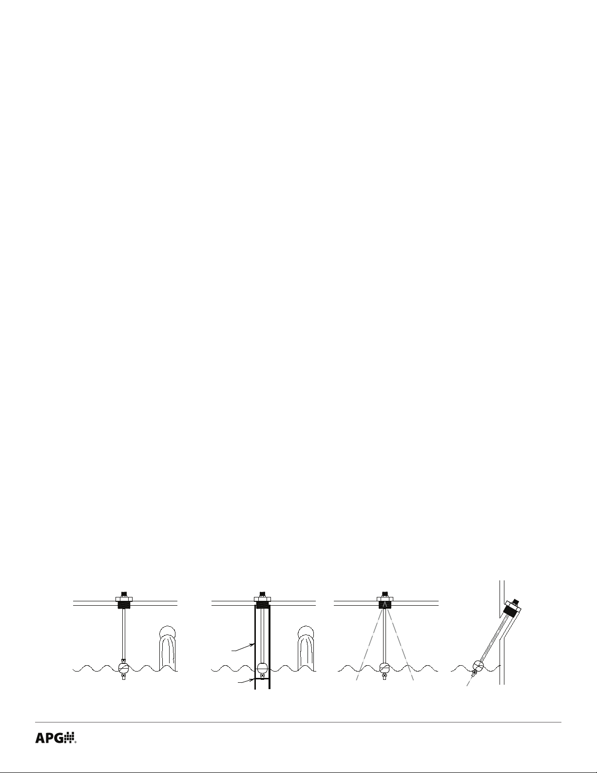
• Do not locate your RP series level sensor near inlets/outlets.
• If there is surface wave action, then use a time-delay relay or stilling tube. If a stilling tube is used, drill
vent holes in the tube and use a spacer to assure the oat has free travel inside the tube (See Figure
2.1).
• The RPE and RPX can be mounted up to 20° from vertical.
Inflow Inflow
Stilling
Tube
20° 20°
Spacer
Figure 2.1
Tel: 1/888/525-7300 • Fax: 1/435/753-7490 • www.apgsensors.com • [email protected]
20°
7
Page 12
• Mounting Instructions
Flange Mounting
Provide the compatible mating ange on the tank and install using a suitable gasket.
Plug Mounting
Provide the compatible female boss on the tank and install the probe with thread tape.
• Electrical Installation
DANGER: Do not remove the housing cover until the atmosphere is determined safe,
and the power supply is turned o.
For RPX and RPE probes with Housings
• Install conduit and/or cable with necessary seal(s) per Drawing 9001930 or 9001932 for hazardous
locations.
• Remove housing cover.
• Check the Wire Color and Terminal Tables on page 6 before making any connections.
• Connect the wire for your system to the appropriate terminal.
• Replace housing cover.
For RPE probes with hookup wires
• Pull probe hookup wires through conduit as appropriate before attaching conduit to top of probe.
• Check the Wire Color and Terminal Tables on page 6 before making any connections.
• Connect the wires from the probe to your system appropriately.
IMPORTANT: Your RPX MUST be installed according to drawing 9001930 (IS Hazard-
ous Installation Drawing For RPX) or 9001932 (Hazardous Mounting Drawing RPX) to meet
listed approvals. Faulty installation will invalidate all safety approvals and ratings.
• Removal Instructions
Removing your RP probe from service must be done with care.
• Ensure all circuits are de-energized, and any hazardous atmosphere has dispersed.
• Disconnect wires, at terminals in RP head or at your system.
• Remove the RP with an appropriately sized wrench (per your mounting type).
• Clean the RP’s stem and oat of any debris (see General Care) and inspect for damage.
• Store your RP in a dry place, at a temperature between -40° and 40°C (-40° and 104°F).
8
Tel: 1/888/525-7300 • Fax: 1/435/753-7490 • www.apgsensors.com • [email protected]
Page 13
Chapter 3: Maintenance
• General Care
Your RP series continuous level probe is very low maintenance and will need little care as long as it is
installed correctly. However, in general, you should:
• Periodically inspect the stem and oat for any trapped debris, sediment, or other foreign material.
• Avoid applications for which the RP was not designed, such as extreme temperatures, contact with
incompatible corrosive chemicals, or other damaging environments.
• If your RPX or RPE has an NPT mount, inspect the threads whenever you remove it from duty or
change its location.
• For units with housing, never leave the housing cover o. If the cover is damaged or lost, order a re-
placement immediately.
• Offset and Span Calibration (4-20 mA output probes only)
NOTE: This procedure can be performed in a non-hazardous area, either prior to
installation, or by temporarily uninstalling your 4-20 mA RP probe.
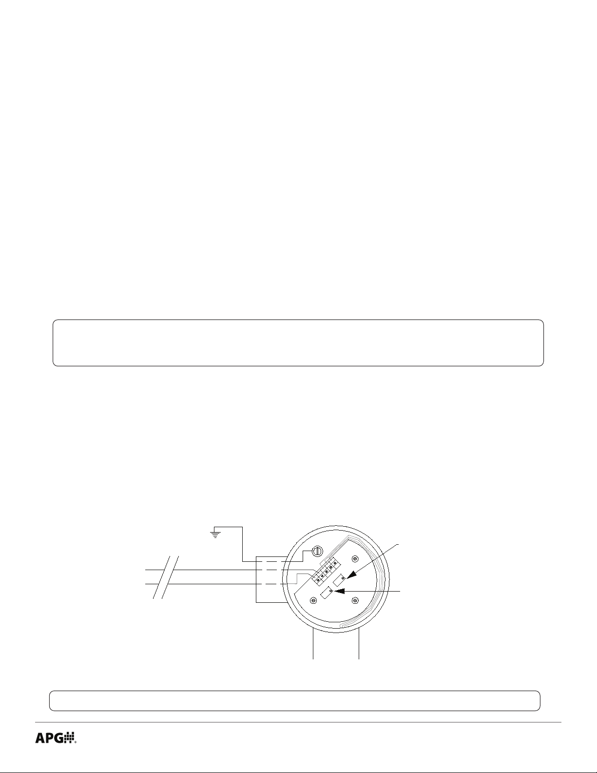
1. Remove the housing cover.
2. Set DC power supply to 24 VDC, and connect to RP probe, with ammeter in loop.
3. Move oat to desired position for 4 mA output.
4. Using a jeweler’s screwdriver or a suitable instrument, adjust the “Oset” potentiometer until you
have a 4 mA output.
5. Move oat to desired position for 20 mA output.
6. Using a jeweler’s screwdriver or a suitable instrument, adjust the “Span” potentiometer until you have
a 20 mA output.
7. Repeat steps 3 - 6 as necessary to ne tune calibration.
Offset (4 mA)
Adjustment
Span (20 mA)
Adjustment
4 to 20ma Out
+24vdc
RED
BLK
WH
OUT
OFFSET
24V
SPAN
Figure 3.1
NOTE: You may also return the RP probe to the factory for repair and/or adjustment.
Tel: 1/888/525-7300 • Fax: 1/435/753-7490 • www.apgsensors.com • [email protected]
9
Page 14

• Repair and Returns
Should your RPX or RPE require service, please contact the factory via phone, email, or online chat. We will
issue you a Return Material Authorization (RMA) number with instructions.
• Phone: 888-525-7300
• Email: [email protected]
• Online chat at www.apgsensors.com
Please have your probe’s part number and serial number available. See Warranty & Warranty Restrictions
for more information.
10
Tel: 1/888/525-7300 • Fax: 1/435/753-7490 • www.apgsensors.com • [email protected]
Page 15
Chapter 4: Hazardous Location Installation and Certication
• IS Hazardous Installation Drawing For RPX
Tel: 1/888/525-7300 • Fax: 1/435/753-7490 • www.apgsensors.com • [email protected]
11
Page 16
• Hazardous Mounting Drawing RPX
12
Tel: 1/888/525-7300 • Fax: 1/435/753-7490 • www.apgsensors.com • [email protected]
Page 17
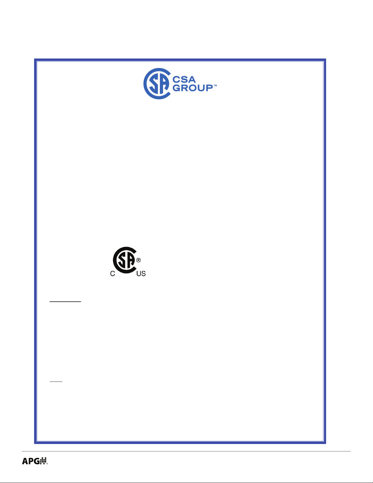
• CSA Certicate of Compliance
Certificate:
2167400
Master Contract:
237484
Project:
70193876
Date Issued:
2019-04-09
Issued To:
Automation Products Group Inc
1025 West 1700 North
Logan, Utah, 84321
United States
Certificate of Compliance
Attention: Joe James
The products listed below are eligible to bear the CSA Mark shown
with adjacent indicators 'C' and 'US' for Canada and US or with adjacent
indicator 'US' for US only or without either indicator for Canada only.
Issued by:
PRODUCTS
CLASS 2252 06 - PROCESS CONTROL EQUIPMENT
CLASS 2252 86 - PROCESS CONTROL EQUIPMENT (Certified to U.S. Standards)
Float Level Sensors, permanently connected, indoor and outdoor use, max. operating ambient 85°C:
Models FLXx and FLRx, rated 220 V, 0.5 A;
Models RPMx, RPXx and RPEx, rated 5 - 15 Vdc, 100 mA, or 12 to 24 Vdc, 4-20mA;
Model RPAx, rated 12 to 24 Vdc, 4-20mA;
Model CTR-0100 (P/Ns 110101 and 110101-0001), Loop Powered 4-20mA Module, rated 4-20mA output is
12 to 24 Vdc.
Note: The above models are Pollution Degree 2, Measurement Category II.
Notes for Models FLXx, FLRx, RPMx, RPAx, RPXx, RPEx:
1. The "x" in the Model designations may be any alpha-numeric character, to denote minor mechanical options,
not affecting safety. Refer to Illustration 28 for Model designator and suffix details.
Albert Jansen
Albert Jansen
DQD 507 Rev 2018-11-12 © 2018 CSA Group. All rights reserved. Page 1
Tel: 1/888/525-7300 • Fax: 1/435/753-7490 • www.apgsensors.com • [email protected]
13
Page 18
Certificate: 2167400
Master Contract: 237484
Project: 70193876
Date Issued: 2019/04/09
2. The equipment is intended to be installed as required by the applicable electrical code (CEC, NEC) and as
specified by the manufacturer’s Installation Instructions.
3. The circuit board P/N STF-CTR-01** from the Model RPMx Probe may be supplied as a component part
where the suitability of the final installation will be inspected by the authority with jurisdiction in the area
where installed.
4. The installation will be inspected by the authority with jurisdiction in the area where installed.
FS-400, FS-410 and FS-500 float switches. Single Seal (MWP 1000psi). Ambient temperature -40°C to 260°C.
Type 4X (NPT Connection Only). Ratings as follows:
0.416A, 240Vac (50/60 Hz)
0.833A, 120Vac (50/60 Hz)/Vdc
1.00A, ≤100Vac (50/60 Hz)/Vdc
Conditions of Acceptability for FS-400, FS-410, and FS-500
The equipment must be connected to a purely resistive load
The equipment must be grounded through final installation
CLASS 2258 02 - PROCESS CONTROL EQUIPMENT - FOR HAZARDOUS LOCATIONS
CLASS 2258 82 - PROCESS CONTROL EQUIPMENT - FOR HAZARDOUS LOCATIONS, U.S.
Requirements
Class I, Division 1, Groups C, and D T3
Float Level Sensors, model FLXx, rated 220 V, 0.5 A, max. or rated 24Vdc, 0.5A, max., and model RPMx
and RPXx, rated 5 - 24 Vdc, 100mA or 12 to 24 Vdc, 4-20mA; operating ambient 40°C.
Ex d, IIB T3
Class I, Zone 1, AEx d, IIB T3
Float Level Sensors, model FLXx, rated 24 Vdc, 0.5 A, max., and model RPMx and RPXx, rated 5 - 24 Vdc,
100mA or 12 to 24 Vdc, 4-20mA; operating ambient 40°C.
Notes for Models FLXx, RPMx, RPXx:
1. The "x" in the Model designations may be any alpha-numeric character, to denote minor mechanical options,
not affecting safety.
2. The equipment is intended to be installed as required by the applicable electrical code (CEC, NEC) and as
specified by the manufacturers Installation Instructions.
3. The installation will be inspected by the authority with jurisdiction in the area where installed.
DQD 507 Rev 2018-11-12 © 2018 CSA Group. All rights reserved. Page 2
14
Tel: 1/888/525-7300 • Fax: 1/435/753-7490 • www.apgsensors.com • [email protected]
Page 19
Certificate: 2167400
Master Contract: 237484
Project: 70193876
Date Issued: 2019/04/09
Class I, Division 2, Groups C, and D T3
Float Level Sensor model FLXx, rated 220 V, 0.5 A, model RPMx and RPXx, rated 5 - 15 Vdc, 100mA, or
rated 12 to 24 Vdc, 4-20mA, and model RPAx, rated 12 to 24 Vdc, 4-20mA; max; operating ambient 85°C.
Notes for Models FLXx, RPMx, RPAx, RPXx:
1. The "x" in the Model designations may be any alpha-numeric character, to denote minor mechanical options,
not affecting safety.
2. The equipment is intended to be installed as required by the applicable electrical code (CEC, NEC) and as
specified by the manufacturers Installation Instructions.
3. The installation will be inspected by the authority with jurisdiction in the area where installed.
Class I Division 1 Groups A, B, C, and D, Class II Division 1 Groups E, F, Class III; T3
Class I Division 2 Groups A, B, C, and D, Class II Division 2 Groups F, G; T200°C
FS-400, FS-410, and FS-500 (NPT Connection) float switches. Single Seal (MWP 1000psi). Ambient temperature
-40°C to 187°C. Type 4X. Seal Not Required. Ratings as follows:
0.416A, 240Vac (50/60 Hz)
0.833A, 120Vac (50/60 Hz)/Vdc
1.00A, ≤100Vac (50/60 Hz)/Vdc
Conditions of Acceptability
The equipment must be connected to a purely resistive load
The equipment must be grounded through final installation
CLASS 2258 03 - PROCESS CONTROL EQUIPMENT - INTRINSICALLY SAFE AND NON INCENDIVE
SYSTEMS - FOR HAZARDOUS LOCATIONS
CLASS 2258 83 - PROCESS CONTROL EQUIPMENT - INTRINSICALLY SAFE AND NON INCENDIVE
SYSTEMS - FOR HAZARDOUS LOCATIONS, CERTIFIED TO U.S. STANDARDS
Class I, Division 2, Groups C, and D T3
Float Level Sensor model RPMx and RPXx, rated 5 - 15 Vdc, 100mA, or rated 12 to 24 Vdc, 4-20mA, and
model RPAx, rated 12 to 24 Vdc, 4-20mA; max; operating ambient 85°C. Field wiring is non-incendive when
installed per drawings 9001415, 9001932 and 9002023 respectively.
Notes for Models RPMx, RPAx, RPXx:
1. The "x" in the Model designations may be any alpha-numeric character, to denote minor mechanical options,
not affecting safety.
2. The equipment is intended to be installed as required by the applicable electrical code (CEC, NEC) and as
specified by the manufacturers Installation Instructions.
3. The installation will be inspected by the authority with jurisdiction in the area where installed.
DQD 507 Rev 2018-11-12 © 2018 CSA Group. All rights reserved. Page 3
Tel: 1/888/525-7300 • Fax: 1/435/753-7490 • www.apgsensors.com • [email protected]
15
Page 20
Certificate: 2167400
Master Contract: 237484
Project: 70193876
Date Issued: 2019/04/09
CLASS 2258 04 - PROCESS CONTROL EQUIPMENT - INTRINSICALLY SAFE, ENTITY
- FOR HAZARDOUS LOCATIONS
CLASS 2258 84 - PROCESS CONTROL EQUIPMENT - INTRINSICALLY SAFE, ENTITY
- FOR HAZARDOUS LOCATIONS, U.S. Requirements
Class I, Division 1, Groups C, and D
Float Level Sensors, model RPMx, RPAx, RPXx and model CTRx loop powered 24Vdc, 4-20mA converter
module, max. operating ambient 85°C; Temperature Code rating T3C; Intrinsically Safe when connected as
per drawing 9001414, 9001423 and 9001930 with the following Entity Parameters: Vmax = 30V, Imax =
130mA, Ci = 3nF, Li = 0uH.
Notes for Models RPMx, RPAx and RPXx:
1. The "x" in the Model designations may be any alpha-numeric character, to denote minor mechanical options,
not affecting safety.
2. The equipment is intended to be installed as required by the applicable electrical code (CEC, NEC) and as
specified by the manufacturers Installation Instructions.
3. The installation will be inspected by the authority with jurisdiction in the area where installed.
DQD 507 Rev 2018-11-12 © 2018 CSA Group. All rights reserved. Page 4
16
Tel: 1/888/525-7300 • Fax: 1/435/753-7490 • www.apgsensors.com • [email protected]
Page 21
Certificate: 2167400
Master Contract: 237484
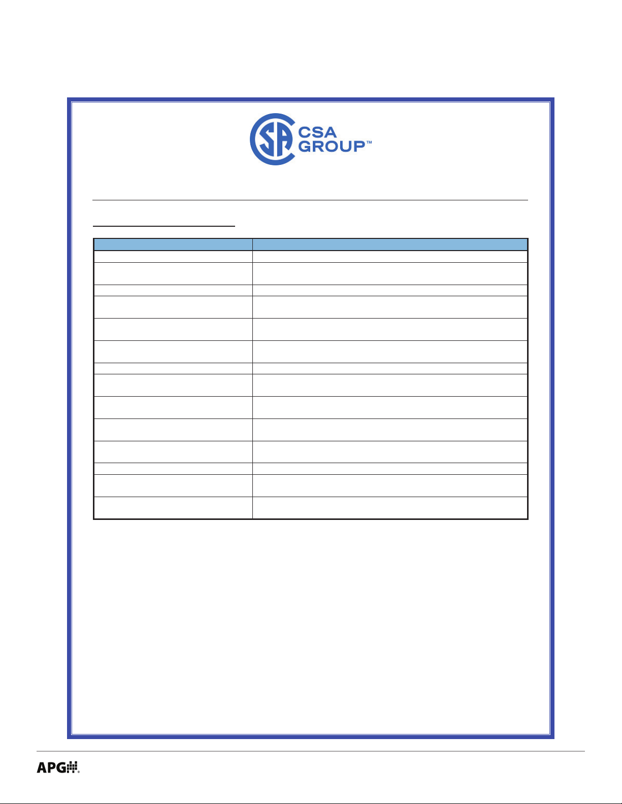
Standard
Title
CSA C22.2 No. 0-10
General Requirements - Canadian Electrical Code, Part II
CSA C22.2 No. 25-17
Enclosures for use in Class II, Division 1, Groups E, F, and G
hazardous locations
CSA C22.2 No. 30-M1987
Explosion-Proof Enclosures for Use in Class I Hazardous Locations
CAN/CSA C22.2 No. 61010-1-12
Safety Requirements for Electrical Equipment for Measurement,
Control, and Laboratory Use, Part 1: General Requirements
CSA C22.2 No. 157-M1992
Intrinsically Safe and Non-Incendive Equipment for Use in
Hazardous Locations
CSA C22.2 No. 213-17
Non-Incendive Electrical Equipment for Use in Class I, Division 2
Hazardous Locations
CSA C22.2 No. 60079-0:15
Explosive atmospheres – Part 0: Equipment – General requirements
CSA C22.2 No. 60079-1:11
Explosive atmospheres – Part 1: Equipment protection by flameproof
enclosures “d”
ANSI/UL 61010-1 (3rd Edition)
Safety Requirements for Electrical Equipment for Measurement,
Control, and Laboratory Use - Part 1: General Requirements
UL 913, Eighth Edition
Intrinsically Safe Apparatus and Associated Apparatus for use in
Class I, II, III, Division 1, Hazardous (Classified) Locations
UL1203, Fifth Edition
Explosion-Proof and Dust-Ignition-Proof Electrical Equipment for
Use in Hazardous (Classified) Locations
UL/ISA 60079-0, Sixth Edition
Explosive atmospheres – Part 0: Equipment – General requirements
UL/ISA 60079-1, Seventh Edition
Explosive Atmospheres – Part 1: Equipment Protection by
Flameproof Enclosures “d”
FM 3611, December 2018
Nonincendive Electrical Equipment for Use in Class I and II,
Divisions 1 and 2 Hazardous (Classified) Locations
Project: 70193876
APPLICABLE REQUIREMENTS
Date Issued: 2019/04/09
DQD 507 Rev 2018-11-12 © 2018 CSA Group. All rights reserved. Page 5
Tel: 1/888/525-7300 • Fax: 1/435/753-7490 • www.apgsensors.com • [email protected]
17
Page 22

APG
R
Tel: 1/888/525-7300 • Fax: 1/435/753-7490 • www.apgsensors.com • [email protected]
Automation Products Group, Inc.
 Loading...