

Page 1

APG
0.5% Industrial Pressure Transmitter
User Manual
Series PT-200
R
Doc #9004739
Rev C, 01/23
Page 2

Table of Contents
Introduction ................................................................................................................ iii
Warranty and Warranty Restrictions .................................................................... iv
Chapter 1: Specications and Options..................................................................... 1
Dimensions ........................................................................................................................................1
Specications ................................................................................................................................... 2
Model Number Congurator .......................................................................................................... 3
Electrical Connectors, Pinout Table, and Supply Power Table .............................................. 4
Wiring Diagram ................................................................................................................................ 4
Chapter 2: Installation and Removal Procedures and Notes ..............................5
Tools Needed .....................................................................................................................................5
Mounting Instructions ................................................................................................................... 5
Electrical Installation ..................................................................................................................... 5
Removal Instructions ..................................................................................................................... 5
Chapter 3: Maintenance .............................................................................................6
General Care ...................................................................................................................................... 6
Repair and Returns .......................................................................................................................... 6
ii
Tel: 1/888/525-7300 • Fax: 1/435/753-7490 • www.apgsensors.com • [email protected]
Page 3

Introduction
Thank you for purchasing a series PT-200 0.5% industrial pressure transmitter from APG. We appreciate
your business! Please take a few minutes to familiarize yourself with your PT-200 and this manual.
The series PT-200 pressure transmitters are rugged, general purpose sensors that oer reliable and
accurate measurements under harsh conditions. The sensor tting is machined from a solid piece of 17-
4PH to provide stable operation when subjected to shock and vibration. PT-200s also incorporate digital
compensation and temperature correction for high accuracy and stability.
Reading your label
Every APG instrument comes with a label that includes the instrument’s model number, part number, serial
number, and a wiring pinout table. Please ensure that the part number and pinout table on your label
match your order.
Tel: 1/888/525-7300 • Fax: 1/435/753-7490 • www.apgsensors.com • [email protected]
iii
Page 4

Warranty and Warranty Restrictions
This product is covered by APG’s waranty to be free from defects in material and workmanship under
normal use and service of the product for 24 months. For a full explanation of our Warranty, please visit
https://www.apgsensors.com/about-us/terms-conditions. Contact Technical Support to recieve a Return
Material Authorization before shipping your product back.
Scan the QR code below to read the full explanation of our Warranty on your tablet or smartphone.
iv
Tel: 1/888/525-7300 • Fax: 1/435/753-7490 • www.apgsensors.com • [email protected]
Page 5
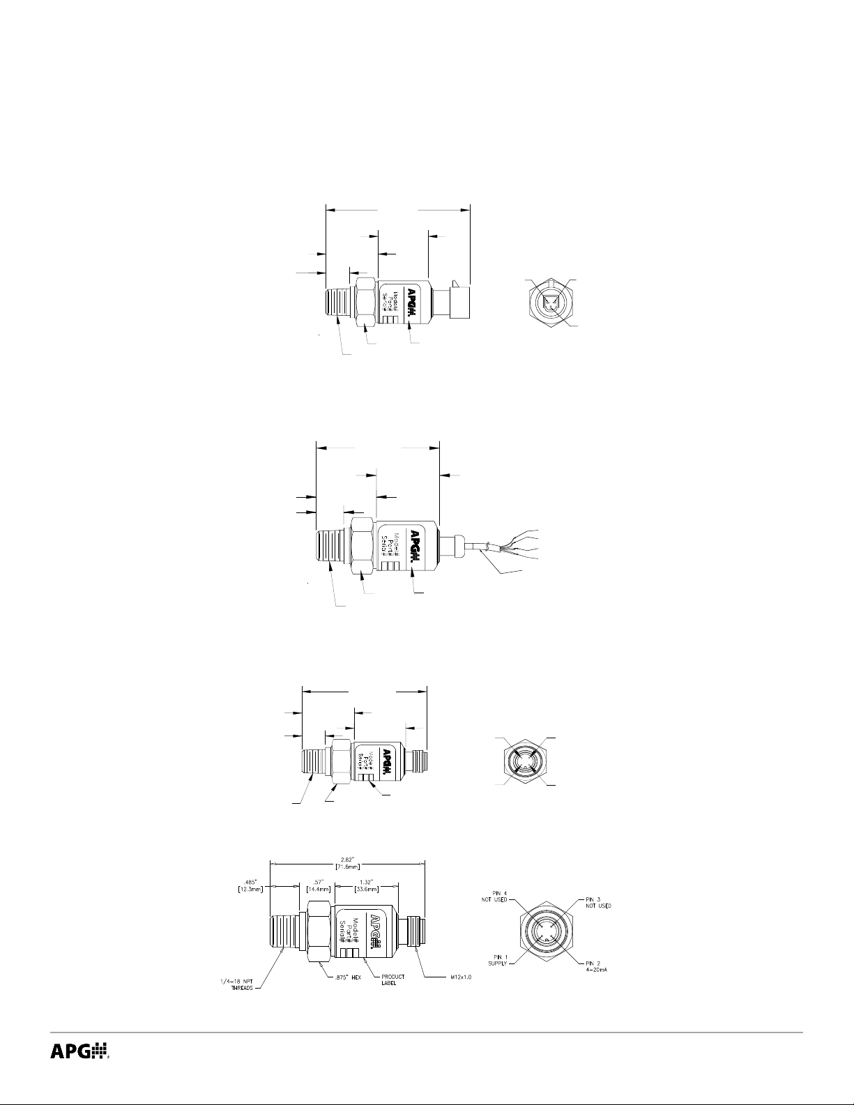
Chapter 1: Specications and Options
.485"
[12.32mm]
1.080"
[27.43mm]
[27.13mm]
1.068"
2.588"
[65.74mm]
1/4-18 NPT
FITTING
.875 HEX
PRODUCT
LABEL
PIN 1
SUPPLY
PIN 2
4-20mA
PIN 3
NOT USED
PIN 4
NOT USED
• Dimensions
2.853"
72.47mm
1.028"
26.11mm
7/8 HEX
1/4"-18 NPT
FITTING
Product Label
Packard Connector
2.148"
54.56mm
1.068"
27.13mm
7/8 HEX
1/4"-18 NPT
FITTING
Product Label
.485"
12.32mm
.485"
12.32mm
1.080"
27.43mm
1.080"
27.43mm
Pin A
Bare Shield
Red
Black
White
Cable Length 60 cm
(23.6")
Pin B
Pin C
3-Conductor Pigtail
M12 Connector
M12 Connector for 100 psi and 150 psi Units
Tel: 1/888/525-7300 • Fax: 1/435/753-7490 • www.apgsensors.com • [email protected]
1
Page 6

• Specications
Performance
Pressure Ranges 0 to 10K PSIG
Analog Output 4-20mA
Proof Pressure 2X Full Scale
Burst Pressure 3.5X Full Scale or 3x Full Scale*
Life span 4 million full scale cycles
Accuracy
Linearity, Hysteresis & Repeatability ±0.5% of Full Scale (BFSL)
Thermal Zero Shift ±0.01% FSO/°C (±0.02% FSO/°F) or ±1.5% FS*
Thermal Span Shift ±0.02% FSO/°C (±0.04% FSO/°F) or ±2% FS*
Long Term Stability <±0.35% FSO/year or< ±0.25% FS/year*
Zero Span Oset Tolerance ±1.75% FSO or ±1.5%FSO*
Environmental
Operating Temperature -10 to 100°C (14 to 212°F) or -10° to 85°C (14° to
185°F)*
Compensated Temperature 0 to 85°C (32 to 185°F) or 0° to 70°C (32° to 158°F)*
Electrical
Supply Voltage (at sensor) 9-32 VDC
Loop Resistance < 100 Ω
Materials of Construction
Wetted Materials 17-4PH Stainless Steel
Mechanical
Process Connection 1/4”-18 Male NPT
Environmental
Enclosure Protection IP65
Note: *This option refers to M12 connectors with 100 psi and 150 psi units only
2
Tel: 1/888/525-7300 • Fax: 1/435/753-7490 • www.apgsensors.com • [email protected]
Page 7

• Model Number Congurator
Model Number: PT-200 -_____ - __________ - _____ - _____
A B C D E
A. Output
□ L1 4-20 mA
B. Common Pressure Ranges
□ 100 □ 250 □ 500 □ 2500 □ 10000
□ 200 □ 300 □ 1000 □ 5000
C. Unit of Measure
□ PSIG Gauge
D. Electrical Connection
□ E4 M12 Connector
□ E5 Pigtail with 2 ft. (60 cm) of cable
□ E51 Packard Connector
E. Process Connection
□ P0 1/4”-18 Male NPT
Tel: 1/888/525-7300 • Fax: 1/435/753-7490 • www.apgsensors.com • [email protected]
3
Page 8
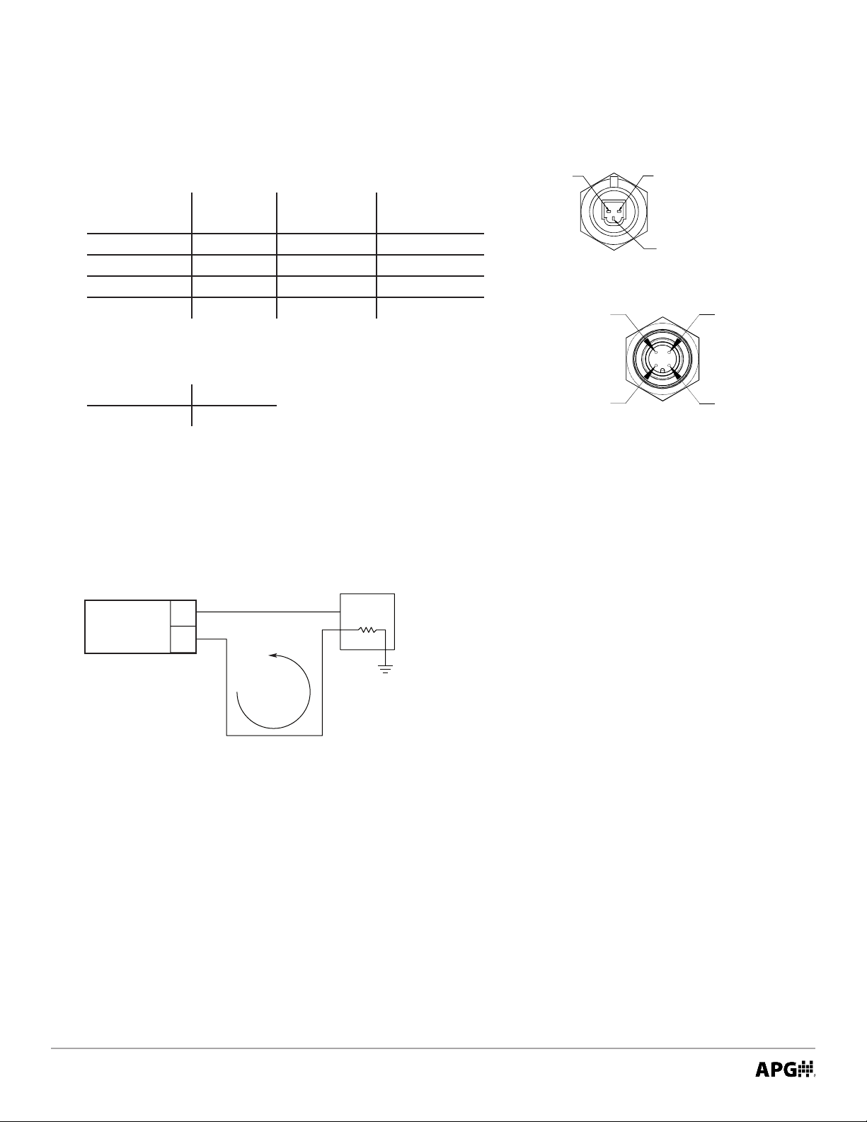
• Electrical Connectors, Pinout Table, and Supply Power Table
Process
PT-200 Pin Out Table
Pin A
Packard
Connector
Excitation - A Black Pin 2
Excitation + B Red Pin 1
No Connection C White Pins 3,4
Gnd - Shield
N/C indicates no connection
Pigtail 3/C
with Shield
M12 Connector
PIN 4
NOT USED
Pin B
Packard
Connector
Pin C
PIN 3
NOT USED
PT-200 Series Supply Power Table
4-20 mA
Power Supply 9-32 VDC
• Wiring Diagram
PT-200
+ Excitation
– Excitation
4-20 mA
Current
Loop
4-20 mA Output Wiring Diagram
Controller
+VDC
R
L
PIN 1
SUPPLY
PIN 2
4-20mA
M12 Connector
The 4-20 mA PT-200 is a 2 wire, loop powered
transducer/transmitter. A voltage of between 9 and 32
VDC must be maintained at this connection. Completion
of the earth or system ground is recommended for
proper circuit protection.
Power supply voltage must be sucient to maintain
a minimum of 9 VDC at the transducer/transmitter
terminals after “dropping” voltage across RL at full scale
current (20 mA). Example: If RL = 250 Ω then “drop” is
0.02 Amps X 250 Ω = 5 volts. Therefore power supply
minimum is 5V + 9 V = 14V.
4
Tel: 1/888/525-7300 • Fax: 1/435/753-7490 • www.apgsensors.com • [email protected]
Page 9

Chapter 2: Installation and Removal Procedures and Notes
• Tools Needed
• 7/8” Hex wrench.
• Thread tape or sealant compound for threaded connections.
• Mounting Instructions
Mounting your pressure transducer is easy if you follow a few simple steps:
• Never over-tighten the sensor. This can compress the diaphragm, changing how it reacts to pressure.
In all cases, tighten the sensor as little as possible to create an adequate seal.
• Always use thread tape or sealant compound on tapered threads. Wrap thread tape in the opposite
direction of the threads so it does not unravel as you screw the sensor into place. Unraveling can cause
uneven distribution and seal failure.
• Always start screwing in your sensor by hand to avoid cross-threading. Thread failure can be a problem
if you damage threads by over-tightening them or by crossing threads.
• Electrical Installation
• Check the pinout table on your PT-200 against your order.
• Check that your electrical system wiring matches the pinout table on your PT-200.
• For instruments with connectors, make the connection. For instruments with pigtails, run the cable to
a junction box in a suitable location to connect to your system.
• Removal Instructions
Removing your PT-200 from service must be done with care. It’s easy to create an unsafe situation, or
damage your sensor, if you are not careful to follow these guidelines:
• Make sure the pressure is completely removed from the line or vessel where your sensor is installed.
Follow any and all procedures for safely isolating any media contained inside the line or vessel.
• Remove the sensor with an 7/8” Hex wrench.
• Carefully clean the sensor’s tting and diaphragm of any debris (see General Care) and inspect for
damage.
• Store your sensor in a dry place, at a temperature between -20 to 125°C (-4 to 257°F).
DANGER: Removing your PT-200 Pressure Transmitter while there is still pressure in
the line could result in injury or death.
Tel: 1/888/525-7300 • Fax: 1/435/753-7490 • www.apgsensors.com • [email protected]
5
Page 10

Chapter 3: Maintenance
• General Care
Your series PT-200 pressure transmitter is very low maintenance and will need little care as long as it was
installed correctly. However, in general, you should:
• Keep the transmitter and the area around it generally clean.
• Avoid applications for which the transmitter was not designed, such as extreme temperatures, contact
with incompatible corrosive chemicals, or other damaging environments.
• Inspect the threads whenever you remove the transmitter from duty or change its location.
• Avoid touching the diaphragm. Contact with the diaphragm, especially with a tool, could permanently
shift the output and ruin accuracy.
• Clean the diaphragm or the diaphragm bore with extreme care. If using a tool is required, make sure it
does not touch the diaphragm.
IMPORTANT: Any contact with the diaphragm can permanently damage the sensor.
Use extreme caution.
• Repair and Returns
Should your series PT-200 pressure transmitter require service, please contact the factory via phone, email,
or online chat. We will issue you a Return Material Authorization (RMA) number with instructions.
• Phone: 888-525-7300
• Email: [email protected]
• Online chat at www.apgsensors.com
Please have your PT-200’s part number and serial number available. See Warranty and Warranty
Restrictions for more information.
6
Tel: 1/888/525-7300 • Fax: 1/435/753-7490 • www.apgsensors.com • [email protected]
Page 11

Page 12

APG
R
Tel: 1/888/525-7300 • Fax: 1/435/753-7490 • www.apgsensors.com • [email protected]
Automation Products Group, Inc.
 Loading...