

Page 1

APG
True Echo
Series PRL for Liquids and Series PRS for Solids
TM
Pulse Radar Level Transmitter
User Manual
Doc #9002986
R
Part #200213
Rev B, 01/2019
Page 2

Table of Contents
Introduction ................................................................................................................ iii
Warranty and Warranty Restrictions .................................................................... iv
Chapter 1: Specications and Options.....................................................................1
Dimensions ........................................................................................................................................1
Specications ...................................................................................................................................2
Model Number Congurators .................................................................................................... 3-4
Electrical Terminals and System Wiring Diagrams ............................................................. 5-6
Chapter 2: Installation and Removal Procedures and Notes ..............................7
Tools Needed .....................................................................................................................................7
Installation Notes ............................................................................................................................7
Mounting Instructions ................................................................................................................... 7
Electrical Installation .....................................................................................................................8
Software Installation .......................................................................................................................8
Removal Instructions ..................................................................................................................... 8
Chapter 3: Maintenance .............................................................................................9
General Care ...................................................................................................................................... 9
Low Dielectric Material Setting ....................................................................................................9
Field Calibration ............................................................................................................................... 9
Repair and Returns ........................................................................................................................ 10
ii
Tel: 1/888/525-7300 • Fax: 1/435/753-7490 • www.apgsensors.com • [email protected]
Page 3

Introduction
Thank you for purchasing a True EchoTM series PRL or PRS Pulse Radar Level Transmitter from APG. We
appreciate your business! Please take a few minutes to familiarize yourself with your True EchoTM Radar
Level Transmitter and this manual.
True EchoTM series Pulse Radar Level Transmitters bring the unassailably accurate level readings of radar
sensors to dicult to solids and liquids. Whether powders or pellets, grains or granules, the True EchoTM
PRS Dual Frequency Pulse Radar Level Transmitter For Solids quickly and accurately reads the complex
reections from piled solids. The True EchoTM PRL Pulse Radar Level Transmitter For Liquids comes with a
variety of housing and antenna materials, but all are IP68 for worry-free level measurement, All True EchoTM
sensors are eld calibratable and fully programmable via RS-232, RS-485 Modbus, or Hart communications.
Reading your label
Every APG instrument comes with a label that includes the instrument’s model number, part number, serial
number, and a wiring pinout table. Please ensure that the part number and pinout table on your label
match your order.
FCC Information
This equipment has been tested and found to comply with limits for a Class A digital device, pursuant to Part
15 of the FCC Rules. These limits are designed to provide reasonable protection against harmful interference
when the equipment is operated in a commercial environment. This equipment generates, uses, and can
radiate radio frequency energy and, if not installed and used in accordance with the instruction manual,
may cause harmful interference to radio communications. Operation of this equipment in a residential area
is likely to cause harmful interference in which case the user will be required to correct the interference at
his own expense.
IMPORTANT: Changes or Modications not expressly approved by factory could void
the user’s authority to operate the equipment.
Tel: 1/888/525-7300 • Fax: 1/435/753-7490 • www.apgsensors.com • [email protected]
iii
Page 4

Warranty and Warranty Restrictions
This product is covered by APG’s warranty to be free from defects in material and workmanship under
normal use and service of the product for 24 months. For a full explanation of our Warranty, please visit
https://www.apgsensors.com/about-us/terms-conditions. Contact Technical Support to receive a Return
Material Authorization before shipping your product back.
Scan the QR code below to read the full explanation of our Warranty on your tablet or smartphone.
iv
Tel: 1/888/525-7300 • Fax: 1/435/753-7490 • www.apgsensors.com • [email protected]
Page 5
Chapter 1: Specications and Options
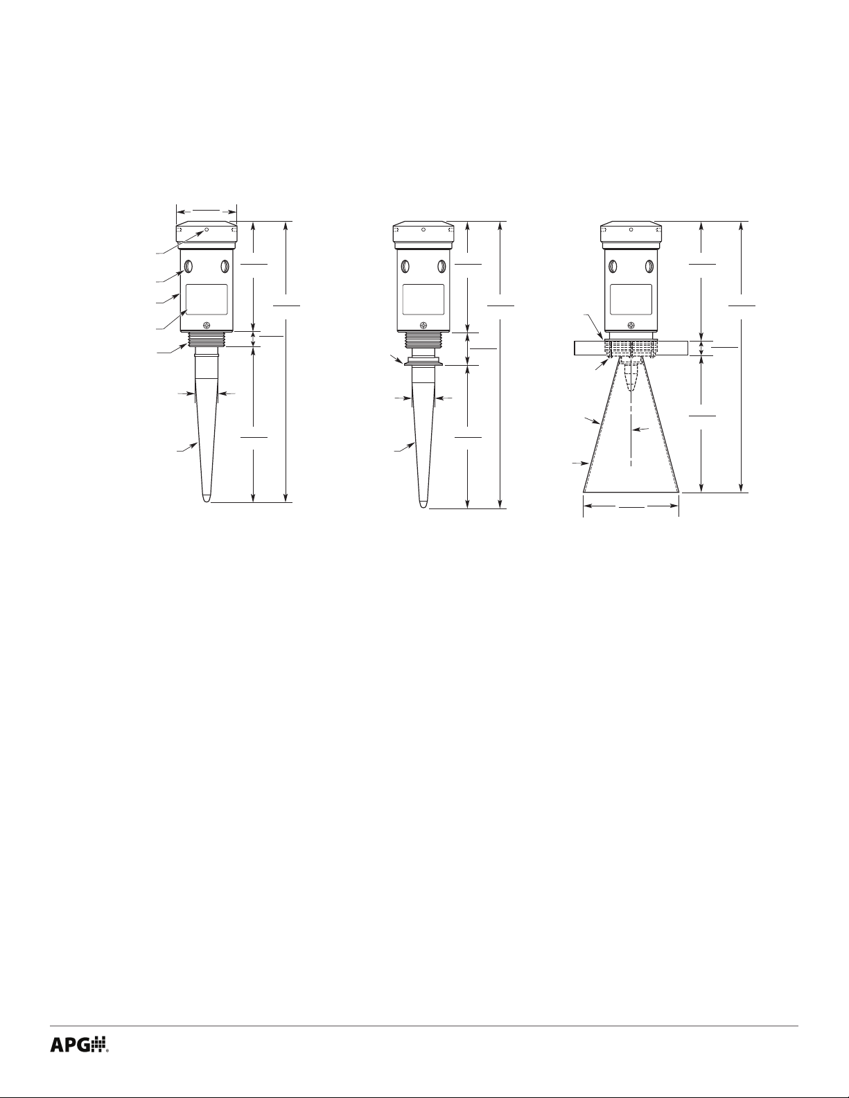
• Dimensions
4.00
Radar with
Standard Antenna
Cover Tool
Access Hole
2x ½" 14 NPT
Conduit Entry
Electronics
Enclosure
FCC Approval
Nameplate
Mounting Threads
2" 11– ½ NPT or
1–½" 11–½ NPT
Teflon Antenna
101.6
Ø1.5
7.30
185.42
10.30
261.62
472.44
1.00
25.40
18.60
Radar with
Sanitary Antenna
2" Tri-Clamp
Fitting
Teflon Antenna
Ø1.5
7.30
185.42
2.125
53.97
9.40
238.76
18.80
477.52
(Not Provided)
Radar with
Horn Antenna
3" ANSI
FF Flange
4x Socket
Head Screws
316 SS
15º
160.02
6.30
7.30
185.42
9.00
228.60
1.60
40.64
17.90
454.66
Tel: 1/888/525-7300 • Fax: 1/435/753-7490 • www.apgsensors.com • [email protected]
1
Page 6

• Specications
Performance
Operating Range 0 - 17 ft. / 0 - 5 m
0 - 50 ft. / 0 - 15 m
0 - 100 ft. / 0 - 30 m
Transducer Frequency PRL: 6.3 MHz
PRS: 6.3 MHz & 26 MHz
Target Dielectric Constant εr > 2
Beam Spread Teon Antenna: 6° from center
316L SS Horn: 3° from center
Accuracy
Accuracy ±0.25% of measured range
Resolution 6.1 μA
Environmental
Housing Operating Temperature -40 to 140°F (-40 to 60°C)
Process/Probe Temperature
Standard Temperature -40 to 176°F (-40 to 80°C)
High Temperature -40 to 350°F (-40 to 177°C)
Sanitary Temperature -40 to 400°F (-40 to 204°C)
Extreme Temperature -40 to 572°F (-40 to 300°C)
Maximum Process Pressures
Standard Temp/Pressure 5 bar (72.5 psi)
Standard Temp/High Pressure 70 bar (1015.3 psi)
High/Sanitary/Extreme Temps 2 bar (29 psi)
Housing Enclosure Rating NEMA 6 / IP 68
Electrical
Supply Voltage 12-30 VDC; 20-35 VDC (HART)
115 VAC @ 60 Hz / 230 VAC @ 50 Hz
Current Draw 70 mA max, 1.68 W @ 24 VDC
1.7 VA for 115/230 VAC
Materials of Construction
Housing Aluminum, 316L Stainless Steel
Antenna Teon, 316L Stainless Steel Horn
Mounting
Teon Antenna 1.5” or 2” NPT
Sanitary Teon Antenna 1.5” or 2” Sanitary Tri-Clamp
316L SS 6” Ø Horn 3” NPT
316L SS 13” Ø Horn 13” Ø Flange
Communication
Output 4-20 mA (shared common or isolated); HART
Calibration & Diagnostics RS-232, RS-485 Modbus, HART
2
Tel: 1/888/525-7300 • Fax: 1/435/753-7490 • www.apgsensors.com • [email protected]
Page 7

• Model Number Congurators
Model Number: PRL - ____ - _____ - _____ - _____ - _____ - _____ - _____
A B C D E F G
A. Range
□ 017
□ 050
□ 100 100 ft (30m)
17 ft (5m)
50 ft (15m)
B. Supply Voltage, Signal
□ V115 115 VAC (60 Hz) - 4-wire, Isolated 4-20 mA
□ V230 230 VAC (50 Hz) - 4-wire, Isolated 4-20 mA
□ V024
common
□ V20L 20-35 VDC - 2-wire HART†
▲
12-30 VDC - 3-wire, 4-20 mA w/ shared
C. PC Communications
□ C2 RS-232
□ C4▲ RS-485
□ CH HART†
D. Housing Material
□ AL▲ Aluminum
□ SS 316 Stainless Steel
Note: † CH HART PC Communications requires V20L 20-35 VDC
Supply Voltage
E. Antenna Material
□ TE▲ Teon Rod
□ TE6 Teon Rod with 6 in. extension
□ TE8 Teon Rod with 8 in. extension
□ LT Teon Rod with 1.5 in. built-in extension
□ ST Sanitary Tri-Clamp mount, Teon Ant.†
□ HT High Temperature Radar, Tefon Ant.
□ PT High Pressure Tefon Rod Ant.(≤70 bar)†††
□ S6 316L Stainless Steel 6” Ø Horn††
□ HS High Temperature Radar, 316L SS Horn††
F. Mounting
□ T15 1.5 in. NPT
□ T2▲ 2 in. NPT
□ T3 3 in. NPT
□ S15 1.5 in. Sanitary Tri-Clamp (ST only)
□ S2 2 in. Sanitary Tri-Clamp (ST only)
□ BF 13 in. Ø 316L SS Bottom Flange (S6, HS only)
G. Firmware
□ S▲ Standard
□ F Fast Firmware
□ OW Oil-Water Interface Detection††††
Note: † ST Teflon Rod Ant. with Sanitary Tri-Clamp mount
requires S15 1.5 in. or S2 2 in. Sanitary Tri-Clamp
mount
Note: †† S6 and HS 316L SS horns require T3 3 in. NPT or BF
13 in. Bottom Flange mount
Note: ††† PT High Pressure Teflon Rod requires T2 2 in NPT
mount
Note: †††† OW Oil-Water Interface Detection requires Supply
Voltage V024: 12-30 VDC and either TE Teflon Rod
antenna or S6 316L SS horn antenna
▲
This option is standard
Tel: 1/888/525-7300 • Fax: 1/435/753-7490 • www.apgsensors.com • [email protected]
3
Page 8

Model Number: PRS - ____ - _____ - _____ - _____ - _____ - _____ - _____
A B C D E F G
A. Range
□ 017
□ 050
□ 100 100 ft (30m)
17 ft (5m)
50 ft (15m)
B. Supply Voltage, Signal
□ V115 115 VAC (60 Hz) - 4-wire, Isolated 4-20 mA
□ V230 230 VAC (50 Hz) - 4-wire, Isolated 4-20 mA
□ V024
common
□ V20L 20-35 VDC - 2-wire HART†
▲
12-30 VDC - 3-wire, 4-20 mA w/ shared
C. PC Communications
□ C2 RS-232
□ C4▲ RS-485
□ CH HART†
Note: † CH HART PC Communications requires V20L 20-35 VDC
Supply Voltage
D. Housing Material
□ AL▲ Aluminum
□ SS 316 Stainless Steel
E. Antenna Material
□ S6▲ 316L Stainless Steel 6” Ø Horn
□ HS High Temp. Radar, 316L SS 6” Ø Horn
F. Mounting
□ T3▲ 3 in. NPT
□ BF 13 in. Ø 316L SS Bottom Flange
□ A3 8 in. Ø Swivel Aimer
G. Firmware
□ S▲ Standard
□ F Fast Firmware
▲
This option is standard
4
Tel: 1/888/525-7300 • Fax: 1/435/753-7490 • www.apgsensors.com • [email protected]
Page 9
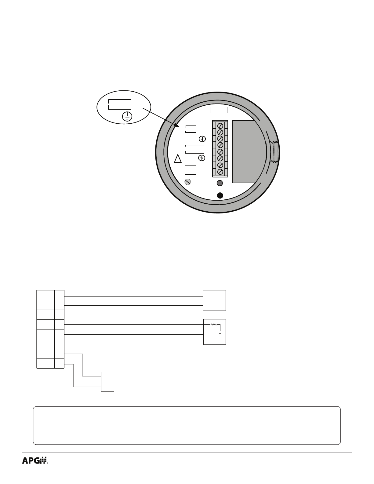
• Electrical Terminals and System Wiring Diagrams
Terminals
12– 30 VDC
+8
-7
6
IN
AC/DC
OUT
4-20 mA
!
RS-232/485
- F1 / 8 A 250 V
L1
8
L2/N
7
6
5
4
3
2
A/TX
1
B/RX
STATUS
CALIBRATION
SWITCH
Power & Control Wiring For 115 or 230 1Ø VAC Supply
115 / 230 VAC Power
True Echo
Terminals
VAC L1
VAC L2/N
Ground
Out +
Out -
Ground
A/TX
B/RX
8
7
6
Isolated 4-20mA Output
5
4
3
2
1
Communication
Network Node
A/TX
B/RX
Supply Voltage
115 / 230 VAC
1 Phase
4-20mA
Input Card
Passive
FUSE
R
L
Recommended Wiring:
• Power - 3 Conductor, 22 AWG,
300V.
• Signal - 1 Shielded Twisted
Pair, 24 AWG, 300V.
• Communication - 1 Shielded
Twisted Pair, 24 AWG, 300V.
NOTE: For RS-232 or RS-485 direct to PC wiring, see Communication Connection Dia-
grams.
Tel: 1/888/525-7300 • Fax: 1/435/753-7490 • www.apgsensors.com • [email protected]
5
Page 10
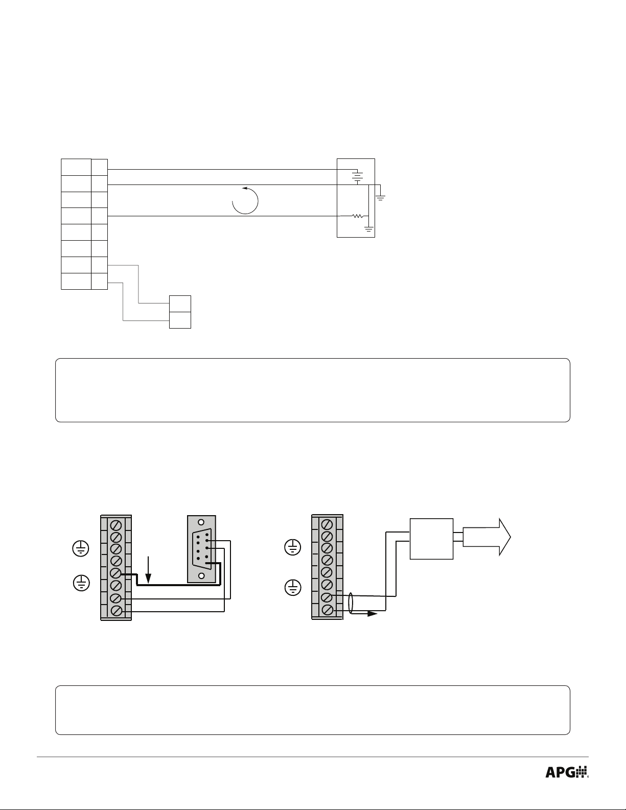
Power & Control Wiring For 12-30 VDC Supply
12-30 VDC Power
Recommended Wiring:
• Power & Signal - 3 Conductor,
True Echo
Terminals
24VDC +
24VDC -
Ground
Out +
Out -
Ground
A/TX
B/RX
8
7
6
4-20mA Output
5
4
3
2
1
4-20 mA
CURRENT
LOOP
Note: For 12-30 VDC sensors, terminal 7
is tied to terminal 4 inside sensor.
Communication
Network Node
A/TX
B/RX
Supply Voltage
4-20mA Input
Process
Controller
+
DC Gnd
R
L
Shielded, 24 AWG, 300V.
• Communication - 1 Shielded
Twisted Pair, 24 AWG, 300V.
NOTE: For RS-232 or RS-485 direct to PC wiring, see Communication Connection Dia-
grams.
Communication Connection Diagrams for RS-232 and RS-485/Modbus
DB9
L1 8
L2/N 7
A/TX 2
PRL/S Terminals
B/RX 1
6
+ 5
-- 4
3
SHIELD
Red
WHT. or BLK.
1
6
2
3
7
4
8
5
9
L1 8
L2 / N 7
PR/S Terminals
A/TX 2
B/RX 1
6
+ 5
-- 4
3
RS485 to
USB
Converter
Red
WHT. or BLK.
Shield
RS-485/Modbus Connection to PCRS-232 Serial Connection to PC
IMPORTANT: Shield wire for RS-485/Modbus must only be connected on one end. If
connecting at radar terminals, use terminal 3.
To PC
USB Port
6
Tel: 1/888/525-7300 • Fax: 1/435/753-7490 • www.apgsensors.com • [email protected]
Page 11
Chapter 2: Installation and Removal Procedures and Notes
• Tools Needed
TM
• You should not need any tools to install your True Echo
using a stand pipe to mount your radar, you will probably need tools to install the stand pipe.
• Installation Notes
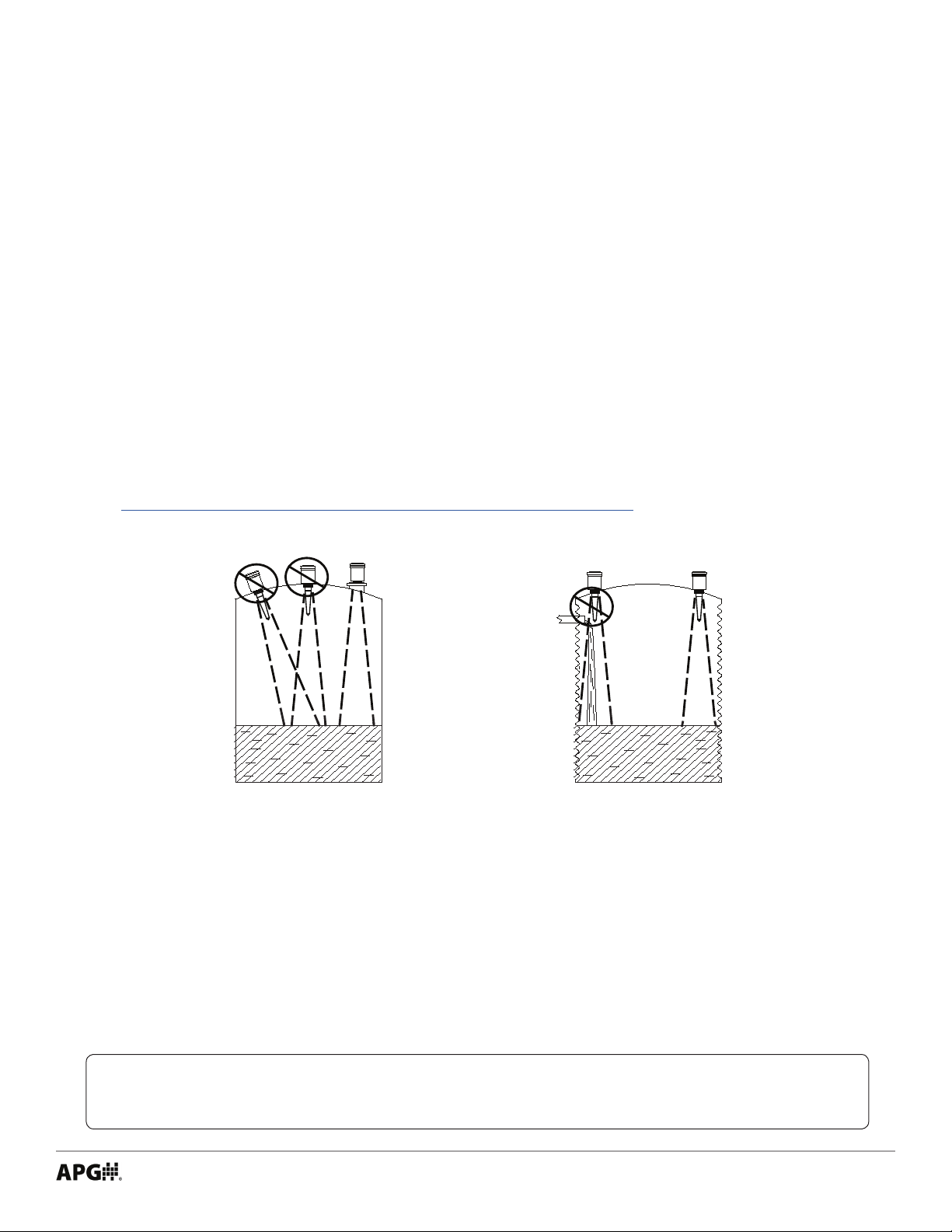
• Mount your True EchoTM series radar so that it has a clear, perpendicular path to the surface being
monitored. Your sensor should be mounted away from tank or vessel inlets. Do not mount radar in
center of domed tank. (See Figure 2.1)
• The radar path should be free from obstructions and as open as possible for the 4° o axis beam pat-
tern.
• If you are using a stand pipe, please see our guide to stand pipes on our website:
http://www.apgsensors.com/about-us/blog/how-to-install-a-stand-pipe.
series Radar Level Transmitter. If you are
Figure 2.1
• Mounting Instructions
Mounting your radar level transmitter is easy if you follow a few simple steps:
• Never over-tighten the sensor.
• Always screw in your sensor by hand to avoid cross-threading. Thread failure can be a problem if you
damage threads by over-tightening them or by crossing threads.
IMPORTANT: Do not over tighten! The sensor should be threaded in only hand tight.
Tel: 1/888/525-7300 • Fax: 1/435/753-7490 • www.apgsensors.com • [email protected]
7
Page 12

NOTE: Do not mount the sensor where the beam will intersect objects such as ll
streams, pipes, ladder rungs, wall seams, or corrugated tank walls.
• Electrical Installation
• Unscrew top lid of radar, exposing electrical terminals.
• Feed wires from your control system through 1/2” NPT conduit hole on side of radar.
• Attach the wires of your control system to the radar according to the appropriate Power & Control
Wiring Diagram on page 5 and 6.
• Secure conduit in 1/2” NPT hole.
• Replace lid of radar.
• Software Installation
• Download the Probe Gateway software ziple from http://apgsensors.com/support.
• Open the zip le.
• Choose “Install” from the options at the top of the zip le window.
• The installation process will prompt you as needed to complete the installation.
• Removal Instructions
• Ensure that power (VAC or VDC, control power, and communication power) to the radar is o.
• Unscrew top lid and detach wires from terminals.
• Disconnect conduit from radar.
• Remove the radar and store it in a dry place, at a temperature between -40° F and 140° F.
• If the radar was installed in a hazardous location, ensure that the cables will not energize while the
sensor is disconnected.
DANGER: Do not disconnect equipment installed in hazardous locations unless power
has been switched o or area is known to be non-hazardous.
8
Tel: 1/888/525-7300 • Fax: 1/435/753-7490 • www.apgsensors.com • [email protected]
Page 13

Chapter 3: Maintenance
• General Care
Your True EchoTM Radar Level Transmitter is very low maintenance and will need little care as long as it was
installed correctly. However, in general, you should:
• Avoid applications for which the sensor was not designed. Follow all temperature range restrictions,
and avoid contact with incompatible corrosive chemicals and fumes, or other damaging environments.
• Inspect the threads whenever you remove the sensor from duty or change its location.
• Low Dielectric Material Setting
Your True EchoTM Pulse Radar Level Transmitter has a setting to more accurately measure target materials
with low dielectrics (ε < 4). The Low Dielectric Materials mode can be turned on or o via the Calibration
Switch on the radar.
• Unscrew the lid of the radar.
- Blinking Green Status LED (see Terminals on Page 5) indicates Low Dielectric Materials mode is ON.
- Solid Green Status LED indicates Low Dielectric Materials mode is OFF.
• To toggle the Low Dielectric Materials mode, press and hold the Calibration Switch button until the
Status LED cycles from Yellow to Red and then o (see Terminals on page 5).
• Replace lid of radar when nished.
• Field Calibration
All True EchoTM Pulse Radar Level Transmitters can be calibrated in the eld to set minimum or maximum
material levels for 4 mA or 20 mA output.
For Full/Maximum Level Calibration
• Turn Low Dielectric Materials mode OFF (see instructions above).
• With target material at maximum desired level, press and hold Calibration Switch button.
- For 20 mA output, release button when Status LED turns Yellow.
- For 4 mA output, release button when Status LED turns RED.
• Status LED will ash after release to conrm setting.
For Empty/Minium Level Calibration
• Turn Low Dielectric Materials mode OFF (see instructions above).
• With target material at minimum desired level, press and hold Calibration Switch button.
- For 20 mA output, release button when Status LED turns Yellow.
- For 4 mA output, release button when Status LED turns RED.
• Status LED will ash after release to conrm setting.
Tel: 1/888/525-7300 • Fax: 1/435/753-7490 • www.apgsensors.com • [email protected]
9
Page 14

IMPORTANT: Low Dielectric Material mode must be OFF before performing level/
output calibration. To calibrate for low dielectric materials, do not turn on Low Dielectric
Material Mode until AFTER performing level/output calibration.
• Repair and Returns
Should your True EchoTM Pulse Radar Level Transmitter require service, please contact the factory via
phone, email, or online chat. We will issue you a Return Material Authorization (RMA) number with
instructions.
• Phone: 888-525-7300
• Email: [email protected]
• Online chat at www.apgsensors.com
Please have your radar’s part number and serial number available. See Warranty and Warranty Restrictions
for more information.
10
Tel: 1/888/525-7300 • Fax: 1/435/753-7490 • www.apgsensors.com • [email protected]
Page 15

Page 16

APG
R
Tel: 1/888/525-7300 • Fax: 1/435/753-7490 • www.apgsensors.com • [email protected]
Automation Products Group, Inc.
 Loading...