

Page 1
APG
Thank You
Thanks for purchasing a MPX series magnetostrictive level sensor from us! We appreciate your
business and your trust. Please take a moment to familiarize yourself with the product and this
manual before installation. If you have any questions, at any time, don’t hesitate to call us at 888525-7300.
NOTE: Scan the QR code to the right to see the full
user manual on your tablet or smartphone. Or visit
www.apgsensors.com/support to nd it on our website.
Table of Contents
MPX Magnetostrictive Level Sensors
Installation Guide
For MPX-E, MPX-E Chemical, and MPX-R
1.Description
2. How To Read Your Label
3. Warranty
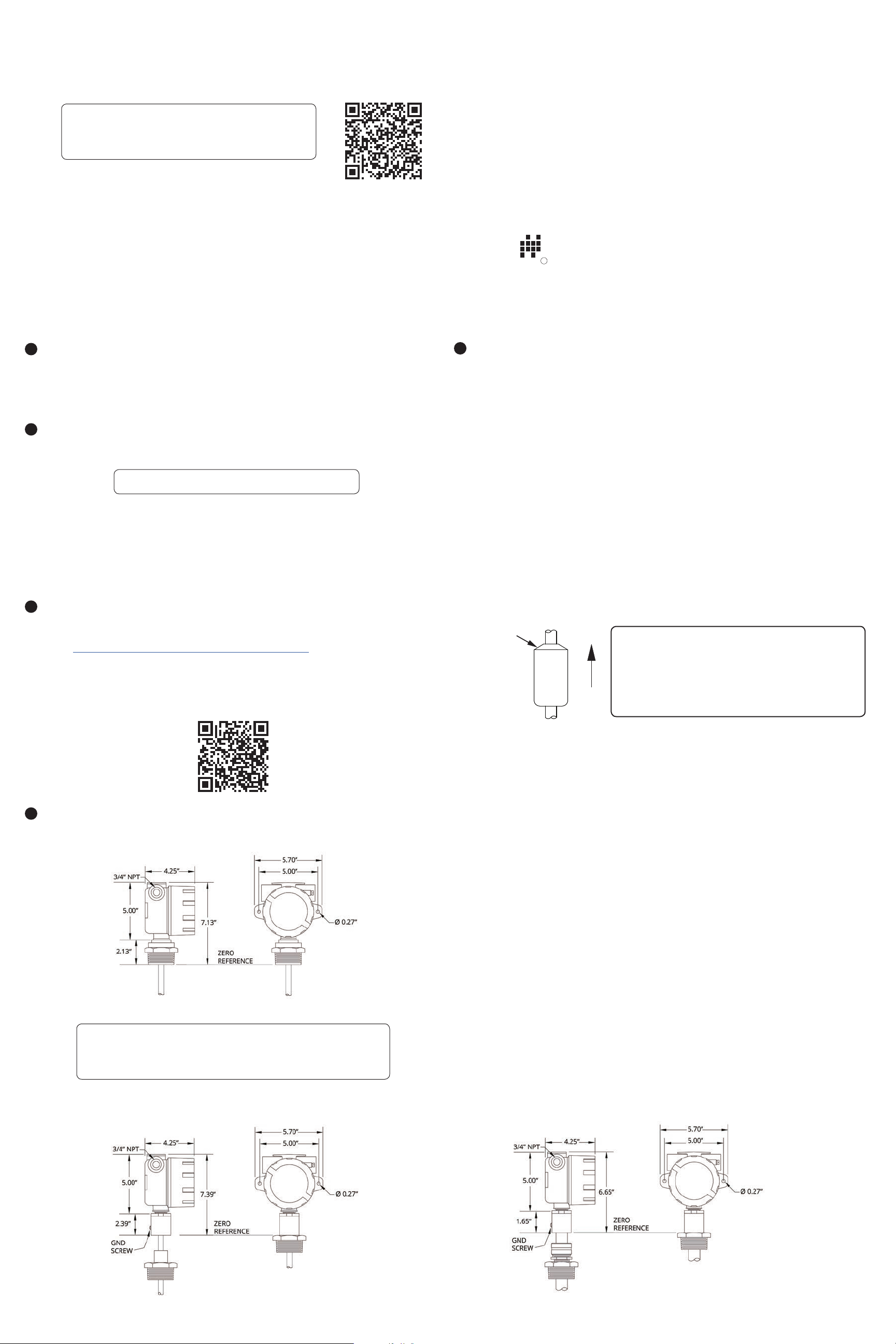
4. Dimensions
Description
1
The MPX series magnetostrictive level sensor provides highly accurate and repeatable level
readings in a wide variety of liquid level measurement applications. It is certied for installation in
hazardous areas in the US and Canada by CSA for Class I, Division 1 & 2 and Class I, Zones 1 and 2
environments.
How To Read Your Label
2
Each label comes with a full model number, a part number, and a serial number. The model
number for the MPX will look something like this:
SAMPLE: MPX-R3-ZY-F2.5WB-120
The model number correlates with all the congurable options and tells you exactly what you have.
Compare the model number to the options on the datasheet to identify your exact conguration.
You can also call us with the model, part, or the serial number and we can help you.
You’ll also nd all hazardous certication information on the label.
Warranty
3
5. Installation Guidelines &
Instructions
6. Sensor and System Wiring
7.General Care
8. Repair Information
9. Hazardous Location Wiring
R
Automation Products Group, Inc.
1025 W 1700 N Logan, UT 84321
www.apgsensors.com | phone: 888-525-7300 | email: [email protected]
Installation Guidelines & Instructions
5
The MPX should be installed in an area--indoors or outdoors--which meets the following
conditions:
• Ambient temperature between -40°F and 185°F (-40°C to 85°C)
• Relative humidity up to 100%
• Altitude up to 2000 meters (6560 feet)
• IEC-664-1 Conductive Pollution Degree 1 or 2
• IEC 61010-1 Measurement Category II
• No chemical corrosive to stainless steel (such as NH
• Ample space for maintenance and inspection
Additional care must be taken to ensure:
• The probe is located away from strong magnetic elds, such as those produced by motors,
transformers, solenoid valves, etc.
• The medium is free from metallic substances and other foreign matter.
• The probe is not exposed to excessive vibration.
• The oat(s) t through the mounting hole. If the oat(s) does/do not t, it/they must be
mounted on the stem from inside the vessel being monitored.
• The oat(s) is/are oriented properly on the stem (See Figure 5.1 below). MPX-E oats will be
installed by the factory. MPX-R oats are typically installed by customer.
, SO2, Cl2, etc.)
3
Part # 122950-0003
Doc #9004081 Rev D
This product is covered by APG’s waranty to be free from defects in material and workmanship
under normal use and service of the product for 24 months. For a full explanation of our Warranty,
please visit https://www.apgsensors.com/about-us/terms-conditions. Contact Technical Support to
receive a Return Material Authorization before shipping your product back.
Scan the QR code below to read the full explanation of our Warranty on your tablet or smartphone.
Dimensions
4
MPX-E Chemical Housing Dimensions
Taper
IMPORTANT: Floats must be oriented properly
UP
Figure 5.1
Installation Instructions:
• If your sensor’s stem and oats t through the mounting hole, carefully lower the assembly
into the vessel, then secure the sensor to the vessel.
• If the oats do not t, mount them on the stem from inside the vessel being monitored. Then
secure the sensor to the vessel.
• For sensors with oat stops, refer to the assembly drawing included with the sensor for oat
stop installation locations.
• For MPX-E Chemical, ensure probe is concentric with tting so as not to scrape chemical
resistant coating o against threads of tting.
Electrical Installation Instructions:
• Remove the housing cover of your MPX.
• Feed system wires into MPX through 3/4” NPT conduit openings. Fittings must be UL/CSA
Listed for CSA installation.
• Connect wires to MPX terminals. Use crimped ferruls on wires, if possible.
• Replace housing cover.
• For lightning and surge protection on MPX-E4, -R4 models, either connect the grounding
screw (see Dimensions section 4) to an earth ground, or ensure that tank mounting of MPX is
grounded.
on the stem, or sensor readings will be inaccurate
and unreliable. Untapered oats will have a sticker
indicating the top of the oat. Remove sticker prior to
use.
NOTE: For MPX-E Chemical with E4 output option, there is no
ground screw on the coupler/NPT. Internal housing ground must be
used for lightning protect.
MPX-E Housing Dimensions MPX-R Housing Dimensions
See Sensor and System Wiring Diagrams (section 6) for Modbus and 4-20 mA wiring examples.
Page 2
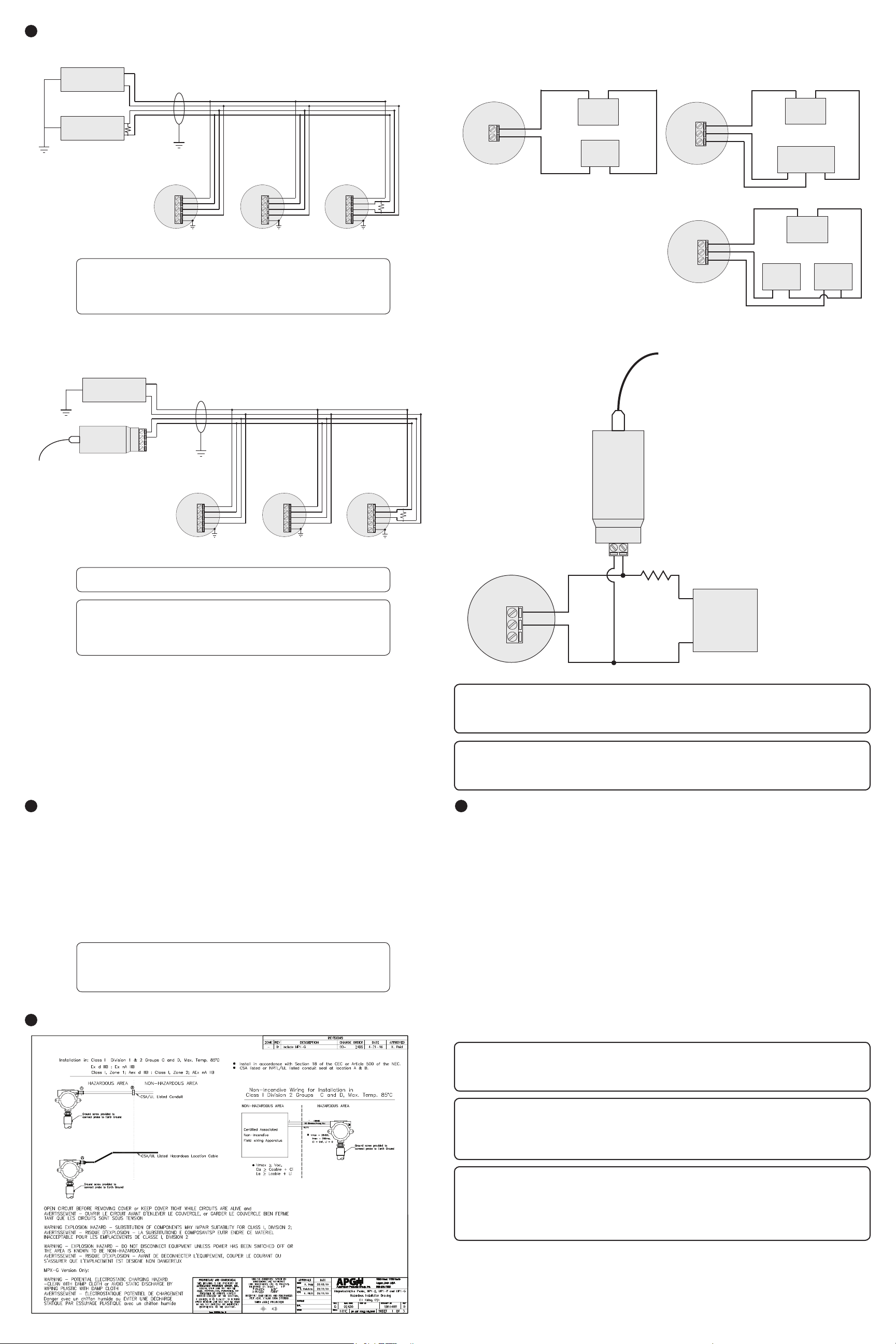
Sensor and System Wiring Diagrams
last sensor
4-20 mA Dual Float Loop Wiring
4-20 mA Single Float Loop Wiring
6
MPX-E4, -R4 Modbus System Wiring
Power
Supply
Master
Device
Note: Earth Ground terminal is factory
connected to internal housing ground
lug.
+12-24 Vdc
GND
RS-485 A
RS-485 B
120 Ω
terminating
resistor
MPX-E4, -R4
series sensor
Sensor 1
V+
B
A
GND
EARTH
GND
Use Shielded Cable
IMPORTANT: For lightning and surge protection on an MPX-E/
R4, either connect the grounding screw (see section 4) to an earth
ground, or ensure that tank mounting of the MPX-E/R4 is grounded.
MPX-E4, -R4
series sensor
Sensor 2
V+
B
A
GND
EARTH
GND
MPX-E4, -R4
series sensor
Sensor 3
V+
B
A
GND
EARTH
GND
120 Ω
terminating
resistor at
last sensor
MPX-E/R2 / MPX-E/R3 System Wiring
(MPX-E2 and MPX-R2 Series)
+
−
Power Source
(12-24 Vdc)
12-24 Vdc
12-24 Vdc
Out
Sensor
Receiver
Input Com
12-24 Vdc
MPX-E/R2 / MPX-E/R3 Programming Wiring
Sensor
Out 1
Out 2
Sensor
Out 1
Out 2
(MPX-E3 and MPX-R3 Series)
+
Power Source
(12-24 Vdc)
Receiver
Input 1 Input 2 Com
OR
+
Power Source
(12-24 Vdc)
Receiver 1
Input Com
−
−
Receiver 2
Input Com
MPX-E4, -R4 Modbus System Wiring with RST-6001
+12-24 Vdc
Power
Supply
RST-6001
Modbus
Controller
USB to computer
with APG Modbus
software
Note: An independent +12-24 Vdc
power supply is required when
using an RST-6001 Modbus Controller.
The RST-6001 can only supply ±5 Vdc,
not the +12-24 Vdc required by the MPX.
Note: Earth Ground terminal is factory
connected to internal housing ground lug.
GND
-5V
+5V
A
B
IMPORTANT: Refer to section 9 for Hazardous Location Wiring.
NOTE: For APG Modbus programming instructions, please see
MPX user manual. APG Modbus software can be downloaded from
www.apgsensors.com/support.
Equivalent 120 Ω
terminating resistor
internal to RST-6001
MPX-E4, -R4
series sensor
Sensor 1
V+
B
A
GND
EARTH
GND
Use Shielded Cable
MPX-E4, -R4
series sensor
Sensor 2
V+
B
A
GND
EARTH
GND
MPX-E4, -R4
series sensor
Sensor 3
V+
B
A
GND
EARTH
GND
120 Ω
terminating
resistor at
Programming configuration is
for programming ONLY. After
programming, sensor must be
reintegrated to 4-20 mA loop
for proper system operation.
MPX-E2, -R2 or
MPX-E3, -R3 series
sensor.
Sensor
12-24 Vdc
Out (1)
Out 2
RST-4100
Out 24V
Load Resistor
(150 Ω to 700 Ω)
Wired in series for
programming.
USB to computer
with APG Modbus
software
Programming Module
and APG Modbus software
required for programming
MPX-E2, -R2 and MPX-E3,
-R3 series sensors.
Note: a minimum of
14 Vdc is required to
establish communications
with the RST-4100
+
Power
Source
(14- 24 Vdc)
−
General Care
7
Your level sensor is very low maintenance and will need little care as long as it was installed
correctly. However, in general, you should periodically inspect your MPX unit to ensure the stem
is free of any heavy buildup that might impede the movement of the oat(s). If sediment or other
foreign matter becomes trapped between the stem and oat(s), detection errors can occur.
If you need to remove the oats(s) from the stem of your MPX, be sure to note the orientation of
the oat(s) prior to removal. This will help ensure proper re-installation of the oat(s).
Also, ensure that the housing cover is snuggly secured. If the cover becomes damaged or is
misplaced, order a replacement immediately.
NOTE: For MPX-E Chemical sensors: Chemical resistant coating
will scar and expose stainless steel if scraped or abused. Use caution
when handling. Always transport in packaging to protect probe and
coating.
IMPORTANT: MPX level sensor MUST be installed according to drawing 9003468
(Hazardous Installation and Non-Incendive Wiring Drawing) in section 9 to meet listed
approvals. Faulty installation will invalidate all safety approvals and ratings.
IMPORTANT: All repairs and adjustments of the MPX level sensor must be made by the
factory. Modifying, disassembling, or altering the MPX, other than patching the chemical
resistant coating on an MPX-E Chemical probe, is strictly prohibited.
Repair Information
8
The MPX-E Chemical’s chemical resistant coating is a durable thermoplastic. This means that if
damage occurs, repair is possible:
• Use a heat gun on a low setting to heat the damaged location until coating becomes soft and
malleable. If coating begins to ripple or bubble, too much heat has been applied.
• With a blunt object, gently smear the coating to recover the damaged area.
• Allow chemical resistant coating patch to cool before reinstalling probe.
• Keep MPX-E Chemical probe and chemical resistant coating away from ammable material
during patching process.
If your MPX level sensor needs repair, contact us via email, phone, or online chat on our website.
We will issue you an RMA number with instructions.
• Phone: 888-525-7300
• Email: [email protected]
• Online chat at www.apgsensors.com
Hazardous Location Wiring
9
DANGER: OPEN CIRCUIT BEFORE REMOVING COVER or KEEP COVER TIGHT WHILE
CIRCUITS ARE ALIVE;
AVERTISSEMENT -- OUVRIR LE CIRCUIT AVANT D’ENLEVER LE COUVERCLE, or GARDER LE
COUVERCLE BIEN FERME TANT QUE LES CIRCUITS SONT SOUS TENSION.
DANGER: WARNING -- EXPLOSION HAZARD -- SUBSTITUTION OF COMPONENTS MAY
IMPAIR SUITABILITY FOR CLASS I, DIVISION 2;
AVERTISSEMENT -- RISQUE D’EXPLOSION -- LA SUBSTITIOND E COMPOSANTSP EUTR
ENDRE CE MATERIEL INACCEPTABLE POUR LES EMPLACEMENTS DE CLASSE I, DIVISION 2.
DANGER: WARNING -- EXPLOSION HAZARD -- DO NOT DISCONNECT EQUIPMENT
UNLESS POWER HAS BEEN SWITCHED OFF OR THE AREA IS KNOWN TO BE NONHAZARDOUS;
AVERTISSEMENT -- RISQUE D’EXPLOSION -- AVANT DE DECONNECTER L’EQUIPEMENT,
COUPER LE COURANT OU S’ASSURER QUE L’EMPLACEMENT EST DESIGNE NON
DANGEREUX.
 Loading...