

Page 1
APG
Thank You
Thanks for purchasing an LOE ultrasonic level sensor from us! We appreciate your business and
your trust. Please take a moment to familiarize yourself with the product and this manual before
installation. If you have any questions, at any time, don’t hesitate to call us at 888-525-7300.
NOTE: Scan the QR code to the right to see the full
user manual on your tablet or smartphone. Or visit
https://www.apgsensors.com/support to nd it on our
website.
Table of Contents
LOE Ultrasonic Level Sensors
Installation Guide
Web Enabled Controller
1.Description
2. How To Read Your Label
3. Warranty
4. Installation Guidelines
Description
1
The LOE Ultrasonic Level Sensor and Web Enabled Controller oers a wide degree of integrated,
exible, remote and local control and monitoring for your system. The LOE can control up to 10
APG Modbus sensors--any combination of level, pressure, magnetostrictive and ultrasonic--and
two output relay terminals. The LOE also had exible power options: it can use either POE or an
independent 12-28 VDC power source.
How To Read Your Label
2
Each label comes with a full model number, a part number, and a serial number. The model
number for your LOE will look something like this:
SAMPLE: LOE-3136
5. Dimensions
6. System Wiring Diagrams
7. Accessing the LOE’s
Embedded Webpage
8. Removal Instructions
9. General Care
10. Repair Information
R
Automation Products Group, Inc.
1025 W 1700 N Logan, UT 84321
www.apgsensors.com | phone: 888-525-7300 | email: [email protected]
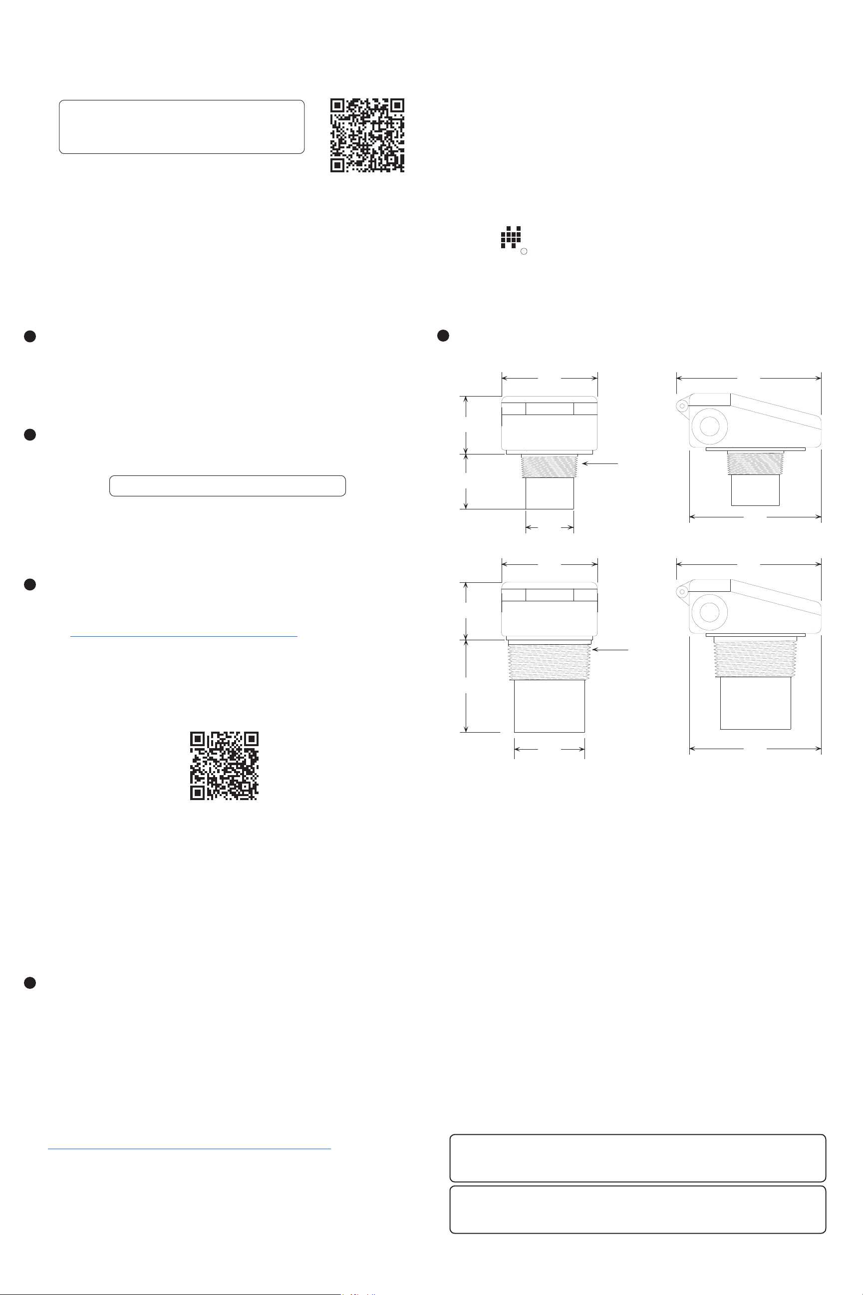
Dimensions
5
LOE-2126, LOE-6126
4.00”
101.6mm
2.40”
61.0mm
2” NPT
2.30”
58.4mm
6.05”
153.7mm
Part # 122950-0019
Doc #9004260 Rev A
The model number tells you exactly what you have. You can also call us with the model, part, or the
serial number and we can help you.
You’ll also nd all hazardous certication information on the label.
Warranty
3
This product is covered by APG’s waranty to be free from defects in material and workmanship
under normal use and service of the product for 24 months. For a full explanation of our Warranty,
please visit https://www.apgsensors.com/about-us/terms-conditions. Contact Technical Support to
recieve a Return Material Authorization before shipping your product back.
Scan the QR code below to read the full explanation of our Warranty on your tablet or smartphone.
2.40”
61.0mm
3.86”
98.0mm
2.00”
50.8mm
4.00”
101.6mm
3.00”
76.2mm
5.50”
139.7mm
LOE-3136
6.05”
153.7mm
3” NPT
5.50”
139.7mm
Installation Guidelines
4
Your LOE should be installed in an area--indoors or outdoors--which meets the following
conditions:
• Ambient temperature between -40°C and 60°C (-40°F to +140°F)
• Ample space for maintenance and inspection
Additional care must be taken to ensure:
• The sensor has a clear, perpendicular sound path to the surface being monitored.
• The sensor is mounted away from tank or vessel walls and inlets.
• The sound path is free from obstructions and as open as possible for the 9° o axis beam
pattern.
• The sensor is tightened by hand to avoid cross-threading.
• If you are using a stand pipe, please see our guide to stand pipes on our website:
http://www.apgsensors.com/about-us/blog/how-to-install-a-stand-pipe.
*Important:
• Use a at head screwdriver to remove knockouts for cables.
• If you are using a stand pipe to mount your LOE, you will probably need tools to install the
stand pipe.
• For any attached Modbus sensors, please consult each sensor’s user manual for installation
notes and instructions.
For sensor conguration and software operation see the full user manual.
Connecting your LOE is easy if you follow a few simple steps:
• Make any relay connections rst.
• Connect LOE to Ethernet/network.
• Connect independent 12-28 VDC supply if not using POE.
• Connect and set up one Modbus sensor at a time.
Please keep the following limitation in mind:
• Up to 10 Modbus sensors can be connected to the LOE in any combination.
IMPORTANT: Each Modbus sensor must be added to the network individually and
assigned a unique Sensor Number before the next sensor can be added.
NOTE: If you can control power to each Modbus sensor individually, you can connect
them all simultaneously, and power them on individually.
Page 2
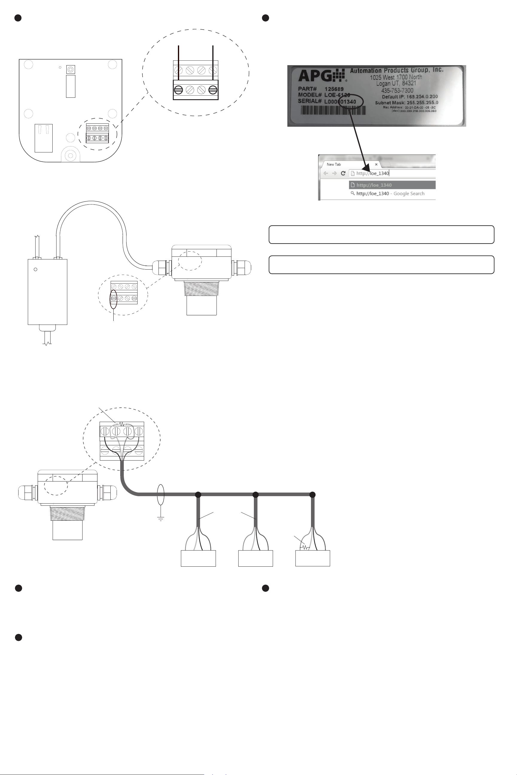
System Wiring Diagrams
6
Accessing the LOE’s Embedded Webpage
7
ETHERNET
PORT
To 12-28 VDC Power Supply
+
-
Each Modbus sensor attached to your LOE must be congured via the LOE’s embedded webpage
before the next sensor can be added. The easiest way to access access the embedded webpage is
to type loe_xxx into a web browser on a computer connected to the same local network as the LOE.
xxx represents the numeric portion of the LOE’s serial number. See Figures 7.1 and 7.2.
COM
OK
SEND/
RESET
TR1 TR1 TR2 TR2
24V B A GND
RS-485
24V B A GND
RS-485
NOTE: Power terminals for 24V and
GND can be used to power Modbus
sensors, or sensors can be powered
independently.
Figure 7.1
To
Network
Connection
POWER
POE
Power
Injector
To AC
power
Figure 7.2
NOTE: Port 6700 must be open on your local netwrook for the LOE to connect.
LAN + DCLAN
24V B A GND
RS-485
NOTE: For access to your remote monitoring site, contact APG.
Terminal inside housing
supplies 24 Vdc to power
attached Modbus devices
when powering the LOE
from a POE source.
270 Ω terminating
resistor NOT internal
to LOE
RS-485
24VBAGND
TR1TR1TR2TR2
Use shielded cable
NOTE: Power terminals for 24V and
GND can be used to power Modbus
sensors, or sensors can be powered
independently.
Note: Terminating resistor size recommended
based on input resistance of LOE. Length
of cable and overall impedence of network may
necessitate a different size resistor.
Trunk Line
Sensor Line Drops
B
A
V+
GND
Sensor 1
B
A
Sensor 2
GND
270 Ω
terminating
resistor at
last sensor
V+
B
A
Sensor 3
GND
V+
Removal Instructions
8
• Disconnect power to the LOE rst.
• Disconnect network connection.
• Disconnect any sensors, relays, and switched inputs.
• Remove the LOE and store it in a dry place, at a temperature between -40° F and 180° F.
General Care
9
Your level sensor is very low maintenance and will need little care as long as it was installed
correctly. However, in general, you should periodically inspect your LOE sensor to ensure the
sensor face is free of any buildup that might impede the function of the sensor. If sediment or other
foreign matter becomes trapped on the sensor face, detection errors can occur.
If you need to remove the sensor, be sure to store it in a dry place at a temperature between -40°
and 180° F.
Repair Information
10
If your LOE ultrasonic level sensor needs repair, contact us via email, phone, or online chat on our
website. We will issue you an RMA number with instructions.
• Phone: 888-525-7300
• Email: [email protected]
• Online chat at www.apgsensors.com
 Loading...