

Page 1

AUT OMATION
Operator’s Manual
PRODUCTS
GROUP, INC.
LFE Series
Industrial OEM Low Cost
Liquid Level Switches
Rev . A1, 4/07
Automation Products Group, Inc.
APG...Providing tailored solutions for measurement applications
Tel: 1/888/525-7300 • Fax: 1/435/753-7490 • www.apgsensors.com • E-mail: sales@apgsensors.com
Page 2

LFE Series Rev . A1, 4/07
Table of Contents
Warranty .............................................................................................................3
Introduction ......................................................................................................4
Speci cation ......................................................................................................4
Installation Location .......................................................................................6
Wiring ..................................................................................................................7
Automation Products Group, Inc.
APG...Providing tailored solutions for measurement applications
2
Tel: 1/888/525-7300 • Fax: 1/435/753-7490 • www.apgsensors.com • sales@apgsensors.com
Page 3

Rev . A1, 4/07 LFE Series
• Warranty and Warranty Restrictions
APG warrants its products to be free from defects of material and workmanship
and will, without charge, replace or repair any equipment found defective
upon inspection at its factory, provided the equipment has been returned,
transportation prepaid, within 24 months from date of shipment from factory.
THE FOREGOING WARRANTY IS IN LIEU OF AND EXCLUDES
ALL OTHER WARRANTIES NOT EXPRESSLY SET FORTH HEREIN,
WHETHER EXPRESSED OR IMPLIED BY OPERATION OF LAW OR
OTHERWISE INCLUDING BUT NOT LIMITED TO ANY IMPLIED
WARRANTIES OF MERCHANTABILITY OR FITNESS FOR A
PARTICULAR PURPOSE.
No representation or warranty, express or implied, made by any sales
representative, distributor, or other agent or representative of APG which is
not specifi cally set forth herein shall be binding upon APG. APG shall not be
liable for any incidental or consequential damages, losses or expenses directly
or indirectly arising from the sale, handling, improper application or use of the
goods or from any other cause relating thereto and APG’s liability hereunder, in
any case, is expressly limited to the repair or replacement (at APG’s option) of
goods.
Warranty is specifi cally at the factory. Any on site service will be provided at
the sole expense of the Purchaser at standard fi eld service rates.
All associated equipment must be protected by properly rated electronic/
electrical protection devices. APG shall not be liable for any damage due
to improper engineering or installation by the purchaser or third parties.
Proper installation, operation and maintenance of the product becomes the
responsibility of the user upon receipt of the product.
Returns and allowances must be authorized by APG in advance. APG will
assign a Return Material Authorization (RMA) number which must appear
on all related papers and the outside of the shipping carton. All returns are
subject to the fi nal review by APG. Returns are subject to restocking charges as
determined by APG’s “Credit Return Policy”.
Automation Products Group, Inc.
APG...Providing tailored solutions for measurement applications
Tel: 1/888/525-7300 • Fax: 1/435/753-7490 • www.apgsensors.com • sales@apgsensors.com
3
Page 4

LFE Series Rev . A1, 4/07
• Introduction
The miniature magnetic level sensors are used for liquid level detection.
They have been designed for reliable operation in small tanks and containers.
Their rugged design and careful engineering make them the optimum
solution for OEM and large volume applications.
• Specifi cations
Operational Versions
LFE-11P-0A ........................................for water - PP, 10 VA, NC
LFE-11P-0B ......................................... for water - PP, 10 VA, NO
LFE-11P-1A ........................................for water - PP, 50 VA, NC
LFE-11P-1B ......................................... for water - PP, 50 VA, NO
LFE-11R-0A ........................................ for oil - Buna, 10 VA, NC
LFE-11R-0B .........................................for oil - Buna, 10 VA, NO
LFE-11R-1A ........................................ for oil - Buna, 50 VA, NC
LFE-11R-1B .........................................for oil - Buna, 50 VA, NO
LFE-12P-0A ......................................... for water - PP, 10 VA, NC
LFE-12P-0B .......................................... for water - PP, 10 VA, NO
LFE-12P-1A ......................................... for water - PP, 50 VA, NC
LFE-12P-1B .......................................... for water - PP, 50 VA, NO
LFE-12R-0A .........................................for oil - Buna, 10 VA, NC
LFE-12R-0B .......................................... for oil - Buna, 10 VA, NO
LFE-12R-1A .........................................for oil - Buna, 50 VA, NC
LFE-12R-1B .......................................... for oil, Buna, 50 VA, NO
Automation Products Group, Inc.
APG...Providing tailored solutions for measurement applications
4
Tel: 1/888/525-7300 • Fax: 1/435/753-7490 • www.apgsensors.com • sales@apgsensors.com
Page 5

Rev . A1, 4/07 LFE Series
• Specifi cations (continued)
Characteristics
Switch Rating (resistive load) (50 VA):
Max contact rating ..........................50 VA AC; 50 W DC
Max current ........................................ 0.5 A AC; 0.5 A DC
Max voltage ........................................ 300 V AC; 300 V DC
7
Life expectancy ................................. 10
operations (at 12 VDC, 5 mA)
Switch Rating (resistive load) (10 VA):
Max contact rating ..........................10 VA AC; 100 W DC
Max current ........................................ 0.2 A AC; 0.3 A DC
Max voltage ........................................ 100 V AC; 100 V DC
Life expectancy ................................. 10
7
operations (at 12 VDC, 5 mA)
Max temperature range .................-14 to 194°F (-10 to 90°C)
Max pressure ...................................... Polypropylene oat: 7 psi (0.5 bar)
Buna oat: 145 psi (10 bar)
Min SG .................................................. Polypropylene oat: 0.9
Buna oat: 0.7
Max viscosity ......................................0.5 Pa s
Max humidity ....................................95% RH
Max impact ......................................... 10 G
Automation Products Group, Inc.
APG...Providing tailored solutions for measurement applications
Tel: 1/888/525-7300 • Fax: 1/435/753-7490 • www.apgsensors.com • sales@apgsensors.com
5
Page 6
LFE Series Rev . A1, 4/07
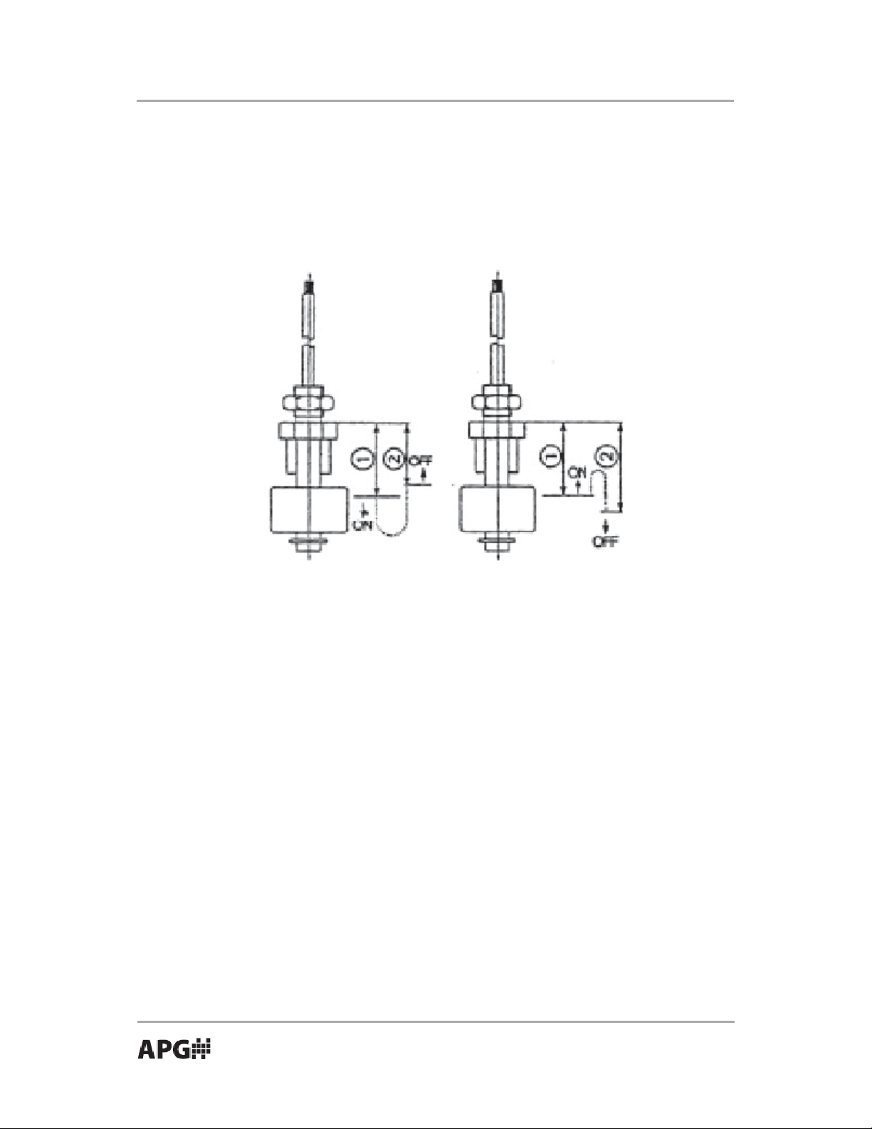
• Installation Location
Locate the LFE at the position where the liquid level variation will actually
make contact with it. DO NOT locate near liquid inlets/outlets. If there is
turbulence, use a time delay relay to dampen the switch action.
Figure A Figure B
LFE-XXX-XA (Switch closes as level falls), see Figure A
LFE-11R LFE-12R LFE-11P LFE-12P
Close as level falls 18 28 15 23
Open as level rises 16.5 26.5 13.5 21.5
LFE-XXX-XB (Switch closes as level rises), see Figure B
LFE-11R LFE-12R LFE-11P LFE-12P
Close as level rises 17 26 14 25
Open as level falls 18.5 27.5 15.5 26.5
Automation Products Group, Inc.
APG...Providing tailored solutions for measurement applications
6
Tel: 1/888/525-7300 • Fax: 1/435/753-7490 • www.apgsensors.com • sales@apgsensors.com
Page 7
Rev . A1, 4/07 LFE Series
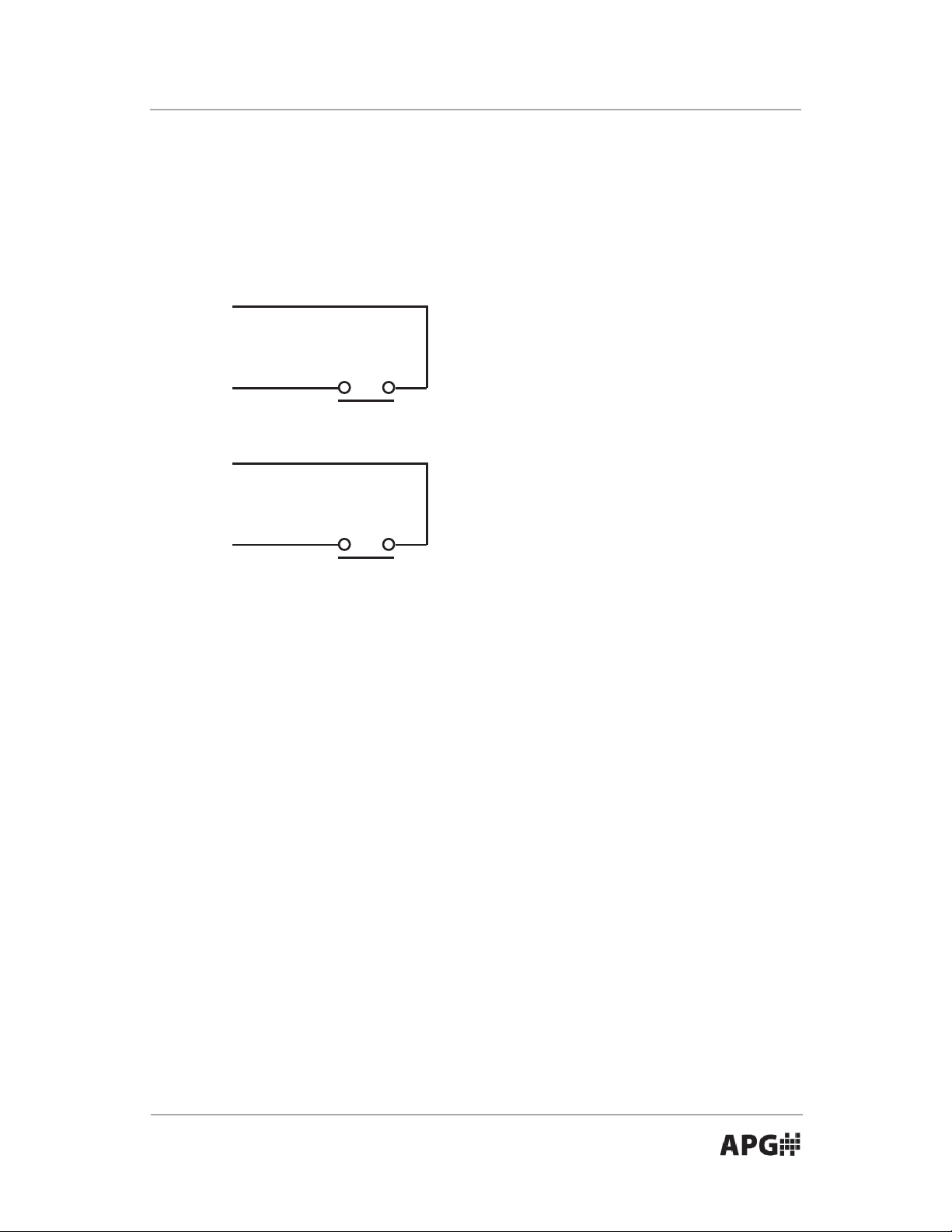
• Wiring
Wiring shall be in accordance with all local codes. Lead wires are #22
AWG, UL listed (UL1430). APG recommends the use of solderless lugs for
Black
Switch Rating (Resistive)
• Max capacity 50 VA, 50 W
• Max current 0.5 A AC, 50 A DC
Black
Yellow
• Max voltage 300 VAC, 300 VDC
Switch Rating (Resistive)
• Max capacity 10 VA, 10 W
• Max current 0.2 A AC, 0.3 A DC
Yellow
• Max voltage 3100 VAC, 100 VDC
Note: Max pull load of the lead wire is 19.6 N. Excessive pulling or kinking of
the lead wire may break the switch.
Caution!
Protection for electrical surges:
• Overvoltage
Reed switches are not designed for the direct starting of inductive
loads such as motors, contactors, solenoid valves, and so on. They are
susceptible to damage from overvoltages. DO NOT EXCEED THE CONTACT
RATINGS. Contact should be wired to miniature relays, suppressors or
similar devices. We recommend the use of our relay unit model RCU-7000.
• Overcurrent
Momentary surge current may be produced by switching lamps or stray
capacity from long cable length. Consequently reed switch is welded.
Contact should be wired to our relay unit model RCU-7000, coils in series
or suppressors.
Automation Products Group, Inc.
APG...Providing tailored solutions for measurement applications
Tel: 1/888/525-7300 • Fax: 1/435/753-7490 • www.apgsensors.com • sales@apgsensors.com
7
Page 8

AUT OMATION
PRODUCTS
GROUP, INC.
APG...Providing tailored solutions
for measurement applications
Automation Products Group, Inc.
Tel: 1/888/525-7300
1/435/753-7300
Fax: 1/435/753-7490
e-mail: sales@apgsensors.com
www.apgsensors.com
Automation Products Group, Inc.
1025 W. 1700 N.
Logan, UT 84321
 Loading...