

Page 1

U
S
ER
MANUAL
#RGZ
VQM9
%
(GDTWCT[
6/
)GPGTCVQT
Advanced Energy Industries,Inc.
1625 Sharp Point Drive
Fort Collins, CO 80525 USA
970.221.4670
technical.support@aei.com
Page 2

Page 3

7UGT/CPWCN
#RGZTM)GPGTCVQT
VQM9
5708009-C
Page 4
Advanced Energy
Read this entire manual and all other publications pertaining to the work to be
performed before you install, operate, or maintain this equipment. Practice all
plant and product safety instructions and precautions. Failure to follow
instructions can cause personal injury and/or property damage. All personnel
who work with or who are exposed to this equipment must take precautions to
protect themselves against serious or possibly fatal bodily injury.
Advanced Energy Industries, Inc., (AE) provides information on its products and
associated hazards, but it assumes no responsibility for the after-sale operation
of the equipment or the safety practices of the owner or user. This equipment
produces or uses potentially lethal high-voltage, high-current, radio frequency
(RF) energy. NEVER DEFEAT INTERLOCKS OR GROUNDS.
All information herein is subject to periodic updates. Inquiries concerning this manual
should be directed to AE. Information provided by AE is believed to be correct and
reliable. However, no responsibility is assumed by AE unless otherwise expressly
taken.
®
Trademarks
Advanced Energy is a registered trademark of Advanced Energy Industries, Inc.
AE is a registered trademark of Advanced Energy Industries, Inc.
Apex is a trademark of Advanced Energy Industries, Inc.
DeviceNet
The Smith
SQS
©
2000
Copyright by Advanced Energy Industries Inc. All rights reserved. Without
written permission, no part of this manual covered by copyright herein may be
reproduced or copied in any form or by any means: graphic, electronic, or mechanical,
including photocopying, recording, taping, or information and retrieval systems.
Written permission must be granted by:
is a registered trademark of Advanced Energy Industries, Inc.
™
is a trademark of Open Vendor Association, Inc., Boca Raton, Fl.
®
chart shown is produced under a copyright license from Analog
Instruments Company, New Providence, New Jersey 07974
™
is a trademark of Tru-Connector Corporation, Peabody, MA
Advanced Energy Industries, Inc.
1625 Sharp Point Drive
Fort Collins, Colorado 80525 USA
4 5708009-C
Page 5

Apex 1 to 5.5 kW Generator
Table of Contents
Chapter 1. Introduction
Read This Section! . . . . . . . . . . . . . . . . . . . . . . . . . . . . . . . . . . . . . . . . . . . . . . . . . 1-1
Using this Manual to Find Information for Your Generator . . . . . . . . . . . . . . . . . . . 1-1
Understanding PIN Numbers and Apex Configuration . . . . . . . . . . . . . . . . . .1-1
Using the PIN to Locate Information in the Manual . . . . . . . . . . . . . . . . . . . . 1-2
Using the PIN to Identify Apex Options . . . . . . . . . . . . . . . . . . . . . . . . . . . . . . 1-3
Interpreting the Manual and Unit Labels . . . . . . . . . . . . . . . . . . . . . . . . . . . . . . . . 1-9
Type Conventions . . . . . . . . . . . . . . . . . . . . . . . . . . . . . . . . . . . . . . . . . . . . . . 1-9
Icons (Symbols) . . . . . . . . . . . . . . . . . . . . . . . . . . . . . . . . . . . . . . . . . . . . . . 1-10
Safety . . . . . . . . . . . . . . . . . . . . . . . . . . . . . . . . . . . . . . . . . . . . . . . . . . . . . . . . . . 1-12
Product Safety/Compliance . . . . . . . . . . . . . . . . . . . . . . . . . . . . . . . . . . . . . . . . . 1-12
Directives and Standards . . . . . . . . . . . . . . . . . . . . . . . . . . . . . . . . . . . . . . . 1-13
Certification . . . . . . . . . . . . . . . . . . . . . . . . . . . . . . . . . . . . . . . . . . . . . . . . . . 1-14
Installation Requirements . . . . . . . . . . . . . . . . . . . . . . . . . . . . . . . . . . . . . . . . . . 1-15
Conditions of Use . . . . . . . . . . . . . . . . . . . . . . . . . . . . . . . . . . . . . . . . . . . . . 1-16
Chapter 2. Theory
General Description . . . . . . . . . . . . . . . . . . . . . . . . . . . . . . . . . . . . . . . . . . . . . . . . 2-1
Functional Description . . . . . . . . . . . . . . . . . . . . . . . . . . . . . . . . . . . . . . . . . . . . . . 2-1
Regulation . . . . . . . . . . . . . . . . . . . . . . . . . . . . . . . . . . . . . . . . . . . . . . . . . . . . 2-1
Cooling . . . . . . . . . . . . . . . . . . . . . . . . . . . . . . . . . . . . . . . . . . . . . . . . . . . . . . 2-1
Interlock . . . . . . . . . . . . . . . . . . . . . . . . . . . . . . . . . . . . . . . . . . . . . . . . . . . . . 2-2
Optional Water Solenoid . . . . . . . . . . . . . . . . . . . . . . . . . . . . . . . . . . . . . . . . . 2-2
Grounding . . . . . . . . . . . . . . . . . . . . . . . . . . . . . . . . . . . . . . . . . . . . . . . . . . . . 2-2
Protection . . . . . . . . . . . . . . . . . . . . . . . . . . . . . . . . . . . . . . . . . . . . . . . . . . . . 2-2
Theory of Operation . . . . . . . . . . . . . . . . . . . . . . . . . . . . . . . . . . . . . . . . . . . . . . . . 2-2
Chapter 3. Specifications
Physical Specifications . . . . . . . . . . . . . . . . . . . . . . . . . . . . . . . . . . . . . . . . . . . . . 3-1
Electrical Specifications . . . . . . . . . . . . . . . . . . . . . . . . . . . . . . . . . . . . . . . . . . . . . 3-5
Input Power Specifications . . . . . . . . . . . . . . . . . . . . . . . . . . . . . . . . . . . . . . . 3-5
Output Electrical Specifications . . . . . . . . . . . . . . . . . . . . . . . . . . . . . . . . . . . 3-6
Other Electrical Specifications . . . . . . . . . . . . . . . . . . . . . . . . . . . . . . . . . . . . 3-9
Cooling Specifications . . . . . . . . . . . . . . . . . . . . . . . . . . . . . . . . . . . . . . . . . . . . . 3-10
Graphical Representations of Flow Rate . . . . . . . . . . . . . . . . . . . . . . . . . . . 3-12
Environmental Specifications . . . . . . . . . . . . . . . . . . . . . . . . . . . . . . . . . . . . . . . . 3-14
5708009-C 5
Page 6

Advanced Energy
®
Chapter 4. Interfaces and Indicators
Apex User Port Options . . . . . . . . . . . . . . . . . . . . . . . . . . . . . . . . . . . . . . . . . . . . . 4-2
25-Pin Apex Standard User Port . . . . . . . . . . . . . . . . . . . . . . . . . . . . . . . . . . 4-2
Satisfying Minimal Requirements for the 25-Pin User Port . . . . . . . . . . . 4-3
Interface Cabling Requirements for 25-pin user port . . . . . . . . . . . . . . . . 4-3
Pin Descriptions for the 25-Pin User Port . . . . . . . . . . . . . . . . . . . . . . . . 4-3
Wiring Diagrams for the Standard 25-Pin User Port . . . . . . . . . . . . . . . . 4-9
15-Pin User Port (Exclusive—Option D) . . . . . . . . . . . . . . . . . . . . . . . . . . . . 4-16
Satisfying Minimal Requirements for Option D 15-Pin User Port . . . . . 4-17
Interface Cabling Requirements for Option D user port . . . . . . . . . . . . . 4-17
Pin Descriptions for Option D User Port . . . . . . . . . . . . . . . . . . . . . . . . 4-18
Wiring Diagrams for Option D 15-Pin User Port . . . . . . . . . . . . . . . . . . 4-20
15-Pin User Port (Exclusive—Option E) . . . . . . . . . . . . . . . . . . . . . . . . . . . . 4-26
Satisfying Minimal Requirements for Option E 15-Pin User Port . . . . . . 4-27
Interface Cabling Requirements for Option E user port . . . . . . . . . . . . . 4-27
Pin Description for Option E User Port . . . . . . . . . . . . . . . . . . . . . . . . . 4-27
Wiring Diagrams for Option E User Port . . . . . . . . . . . . . . . . . . . . . . . . 4-32
Apex Host Port Options . . . . . . . . . . . . . . . . . . . . . . . . . . . . . . . . . . . . . . . . . . . . 4-37
Host Port—RS-232 With AE Bus . . . . . . . . . . . . . . . . . . . . . . . . . . . . . . . . . 4-37
RS-232, AE Bus Host Port Cabling Requirements . . . . . . . . . . . . . . . . 4-39
Communicating Through the RS-232, AE Bus Host Port . . . . . . . . . . . 4-39
AE Bus Protocol . . . . . . . . . . . . . . . . . . . . . . . . . . . . . . . . . . . . . . . . . . . 4-40
Creating an Ideal Communications Transaction . . . . . . . . . . . . . . . . . . 4-42
Host/Apex Communications Transaction Example . . . . . . . . . . . . . . . . 4-43
Command Status Response (CSR) Codes—RS-232, AE Bus Host . . . 4-44
Command Set for the RS-232, AE Bus Host Port . . . . . . . . . . . . . . . . . 4-45
Host Port—Profibus . . . . . . . . . . . . . . . . . . . . . . . . . . . . . . . . . . . . . . . . . . . 4-58
AE Profibus Protocol . . . . . . . . . . . . . . . . . . . . . . . . . . . . . . . . . . . . . . . 4-59
Profibus/Apex Software Commands . . . . . . . . . . . . . . . . . . . . . . . . . . . 4-63
Profibus Command Set . . . . . . . . . . . . . . . . . . . . . . . . . . . . . . . . . . . . . 4-66
Host Port—DeviceNet . . . . . . . . . . . . . . . . . . . . . . . . . . . . . . . . . . . . . . . . . . 4-72
DeviceNet Interface Characteristics . . . . . . . . . . . . . . . . . . . . . . . . . . . 4-73
DeviceNet Rotary Switches: Baud Rate and Addressing . . . . . . . . . . . 4-74
DeviceNet Control Panel LEDs . . . . . . . . . . . . . . . . . . . . . . . . . . . . . . . 4-74
DeviceNet Operation . . . . . . . . . . . . . . . . . . . . . . . . . . . . . . . . . . . . . . . 4-76
Apex Status Indicators (LEDs) . . . . . . . . . . . . . . . . . . . . . . . . . . . . . . . . . . . . . . . 4-79
Apex Panel Illustrations . . . . . . . . . . . . . . . . . . . . . . . . . . . . . . . . . . . . . . . . . . . . 4-80
Chapter 5. Installation, Setup, and Operation
Installing the Generator . . . . . . . . . . . . . . . . . . . . . . . . . . . . . . . . . . . . . . . . . . . . . 5-1
Unpacking . . . . . . . . . . . . . . . . . . . . . . . . . . . . . . . . . . . . . . . . . . . . . . . . . . . . 5-1
Grounding . . . . . . . . . . . . . . . . . . . . . . . . . . . . . . . . . . . . . . . . . . . . . . . . . . . . 5-1
Spacing Requirements . . . . . . . . . . . . . . . . . . . . . . . . . . . . . . . . . . . . . . . . . . 5-2
Mounting the Generator . . . . . . . . . . . . . . . . . . . . . . . . . . . . . . . . . . . . . . . . . 5-4
Connecting Cooling Water . . . . . . . . . . . . . . . . . . . . . . . . . . . . . . . . . . . . . . . 5-4
6 5708009-C
Page 7

Apex 1 to 5.5 kW Generator
Installing the Optional Water Control . . . . . . . . . . . . . . . . . . . . . . . . . . . . . . . 5-4
Connecting Output Power . . . . . . . . . . . . . . . . . . . . . . . . . . . . . . . . . . . . . . . . 5-5
Connecting Input Power . . . . . . . . . . . . . . . . . . . . . . . . . . . . . . . . . . . . . . . . . 5-6
ODU Connector . . . . . . . . . . . . . . . . . . . . . . . . . . . . . . . . . . . . . . . . . . . . 5-7
NonTerminated, four-Conductor Pigtail . . . . . . . . . . . . . . . . . . . . . . . . . . 5-8
Harting Type Han-Q Connector . . . . . . . . . . . . . . . . . . . . . . . . . . . . . . . . 5-9
Connecting I/O and Auxiliary Connectors . . . . . . . . . . . . . . . . . . . . . . . . . . . 5-10
To Control the Generator Through a User Port . . . . . . . . . . . . . . . . . . . 5-11
To Control the Generator through a Host port . . . . . . . . . . . . . . . . . . . . 5-11
To Use the Common Exciter (CEX) Feature (optional) . . . . . . . . . . . . . 5-12
First Time Operation . . . . . . . . . . . . . . . . . . . . . . . . . . . . . . . . . . . . . . . . . . . . . . 5-12
Normal Operation . . . . . . . . . . . . . . . . . . . . . . . . . . . . . . . . . . . . . . . . . . . . . . . . . 5-13
Understanding and Setting Up Pulsing Output . . . . . . . . . . . . . . . . . . . . . . . . . . 5-13
Understanding Pulsing . . . . . . . . . . . . . . . . . . . . . . . . . . . . . . . . . . . . . . . . . 5-14
Enabling and Setting Pulsing . . . . . . . . . . . . . . . . . . . . . . . . . . . . . . . . . . . . 5-14
Chapter 6. Troubleshooting and Customer Support
Troubleshooting guide . . . . . . . . . . . . . . . . . . . . . . . . . . . . . . . . . . . . . . . . . . . . . . 6-1
Checks with the Power Off . . . . . . . . . . . . . . . . . . . . . . . . . . . . . . . . . . . . . . . 6-1
Troubleshooting Questions . . . . . . . . . . . . . . . . . . . . . . . . . . . . . . . . . . . . . . . 6-3
Troubleshooting Procedures . . . . . . . . . . . . . . . . . . . . . . . . . . . . . . . . . . . . . . . . . 6-4
AC On LED not Lit . . . . . . . . . . . . . . . . . . . . . . . . . . . . . . . . . . . . . . . . . . . . . 6-4
Alarm LED Lit . . . . . . . . . . . . . . . . . . . . . . . . . . . . . . . . . . . . . . . . . . . . . . . . . 6-4
Overtemp LED on Solid . . . . . . . . . . . . . . . . . . . . . . . . . . . . . . . . . . . . . . . . . 6-4
Overtemp LED is Flashing . . . . . . . . . . . . . . . . . . . . . . . . . . . . . . . . . . . . . . . 6-4
Interlock LED is not Lit . . . . . . . . . . . . . . . . . . . . . . . . . . . . . . . . . . . . . . . . . . 6-5
RF ON LED Flashing . . . . . . . . . . . . . . . . . . . . . . . . . . . . . . . . . . . . . . . . . . . 6-5
Power Limit LED is Lit . . . . . . . . . . . . . . . . . . . . . . . . . . . . . . . . . . . . . . . . . . . 6-5
External Load Checks - Open/Short RF Output Path . . . . . . . . . . . . . . . . . . . 6-6
Error Codes . . . . . . . . . . . . . . . . . . . . . . . . . . . . . . . . . . . . . . . . . . . . . . . . . . . . . . 6-7
AE Customer Support . . . . . . . . . . . . . . . . . . . . . . . . . . . . . . . . . . . . . . . . . . . . . 6-11
Returning Units for Repair . . . . . . . . . . . . . . . . . . . . . . . . . . . . . . . . . . . . . . . . . . 6-12
Warranty . . . . . . . . . . . . . . . . . . . . . . . . . . . . . . . . . . . . . . . . . . . . . . . . . . . . . . . 6-13
Authorized Returns . . . . . . . . . . . . . . . . . . . . . . . . . . . . . . . . . . . . . . . . . . . . 6-13
Warranty Statement . . . . . . . . . . . . . . . . . . . . . . . . . . . . . . . . . . . . . . . . . . . 6-14
5708009-C 7
Page 8

Advanced Energy
®
8 5708009-C
Page 9

Apex 1 to 5.5 kW Generator
List of Figures
Serial number identification tag . . . . . . . . . . . . . . . . . . . . . . . . . . . . . . . . . . . . . . . . . . . 1-2
Example configuration note . . . . . . . . . . . . . . . . . . . . . . . . . . . . . . . . . . . . . . . . . . . . . . 1-3
Theory of operation block diagram . . . . . . . . . . . . . . . . . . . . . . . . . . . . . . . . . . . . . . . . 2-3
Flow Rate vs. Pressure Drop . . . . . . . . . . . . . . . . . . . . . . . . . . . . . . . . . . . . . . . . . . . 3-12
Water flow vs. Inlet Temperature . . . . . . . . . . . . . . . . . . . . . . . . . . . . . . . . . . . . . . . . 3-13
User Port connector 25 Pin APEX Standard . . . . . . . . . . . . . . . . . . . . . . . . . . . . . . . . . 4-2
User port connector 15 Pin Exclusive for configuration D . . . . . . . . . . . . . . . . . . . . . . 4-17
User Port connector 15 pin exclusive for Configuration E . . . . . . . . . . . . . . . . . . . . . . 4-26
RS-232, AE Bus Host port connector . . . . . . . . . . . . . . . . . . . . . . . . . . . . . . . . . . . . . 4-38
Graphic representation of a RS-232, AE Bus message packet . . . . . . . . . . . . . . . . . 4-40
AE Bus communications transaction . . . . . . . . . . . . . . . . . . . . . . . . . . . . . . . . . . . . . . 4-42
AE Bus communications transaction example . . . . . . . . . . . . . . . . . . . . . . . . . . . . . . 4-44
Host port connector with Profibus . . . . . . . . . . . . . . . . . . . . . . . . . . . . . . . . . . . . . . . . 4-59
DeviceNet connector . . . . . . . . . . . . . . . . . . . . . . . . . . . . . . . . . . . . . . . . . . . . . . . . . . 4-72
DeviceNet control panel . . . . . . . . . . . . . . . . . . . . . . . . . . . . . . . . . . . . . . . . . . . . . . . 4-74
Front Panel . . . . . . . . . . . . . . . . . . . . . . . . . . . . . . . . . . . . . . . . . . . . . . . . . . . . . . . . . 4-81
Rear panel . . . . . . . . . . . . . . . . . . . . . . . . . . . . . . . . . . . . . . . . . . . . . . . . . . . . . . . . . . 4-82
Apex dimensions . . . . . . . . . . . . . . . . . . . . . . . . . . . . . . . . . . . . . . . . . . . . . . . . . . . . . . 5-3
Water control connector . . . . . . . . . . . . . . . . . . . . . . . . . . . . . . . . . . . . . . . . . . . . . . . . 5-5
Optional water solenoid connector . . . . . . . . . . . . . . . . . . . . . . . . . . . . . . . . . . . . . . . . 5-5
Output connector . . . . . . . . . . . . . . . . . . . . . . . . . . . . . . . . . . . . . . . . . . . . . . . . . . . . . . 5-6
ODU input connector . . . . . . . . . . . . . . . . . . . . . . . . . . . . . . . . . . . . . . . . . . . . . . . . . . . 5-8
Harting type Han-Q connector . . . . . . . . . . . . . . . . . . . . . . . . . . . . . . . . . . . . . . . . . . 5-10
5708009-C 9
Page 10

Advanced Energy
®
10 5708009-C
Page 11

Apex 1 to 5.5 kW Generator
List of Tables
Apex PIN Positions and Associated Options . . . . . . . . . . . . . . . . . . . . . . . . . . . . . . . . 1-4
Electromagnetic Compatibility (EMC) . . . . . . . . . . . . . . . . . . . . . . . . . . . . . . . . . . . . . 1-13
Safety . . . . . . . . . . . . . . . . . . . . . . . . . . . . . . . . . . . . . . . . . . . . . . . . . . . . . . . . . . . . .1-13
Block Diagram Explanation . . . . . . . . . . . . . . . . . . . . . . . . . . . . . . . . . . . . . . . . . . . . . . 2-3
Physical Specifications . . . . . . . . . . . . . . . . . . . . . . . . . . . . . . . . . . . . . . . . . . . . . . . . . 3-2
Input Power Specifications . . . . . . . . . . . . . . . . . . . . . . . . . . . . . . . . . . . . . . . . . . . . . . 3-5
Output Specifications . . . . . . . . . . . . . . . . . . . . . . . . . . . . . . . . . . . . . . . . . . . . . . . . . . 3-6
Other Electrical Specifications . . . . . . . . . . . . . . . . . . . . . . . . . . . . . . . . . . . . . . . . . . . 3-9
Cooling Specification . . . . . . . . . . . . . . . . . . . . . . . . . . . . . . . . . . . . . . . . . . . . . . . . . . 3-10
Climatic Specifications . . . . . . . . . . . . . . . . . . . . . . . . . . . . . . . . . . . . . . . . . . . . . . . . 3-14
Environmental Specifications . . . . . . . . . . . . . . . . . . . . . . . . . . . . . . . . . . . . . . . . . . . 3-14
User Port 25-Pin APEX Standard Pin Descriptions . . . . . . . . . . . . . . . . . . . . . . . . . . . 4-4
User Port (15-pin) Connector Pins Exclusive for Configuration D . . . . . . . . . . . . . . . . 4-18
User Port (15-pin) Connector Pins Exclusive for Configuration E . . . . . . . . . . . . . . . . 4-28
RS-232, AE Bus Host Port Pin Descriptions . . . . . . . . . . . . . . . . . . . . . . . . . . . . . . . . 4-39
CSR Codes for RS-232, AE Bus Host . . . . . . . . . . . . . . . . . . . . . . . . . . . . . . . . . . . . 4-44
Host Port Commands for RS-232 with AE Bus . . . . . . . . . . . . . . . . . . . . . . . . . . . . . . 4-45
Profibus Host Port Pins . . . . . . . . . . . . . . . . . . . . . . . . . . . . . . . . . . . . . . . . . . . . . . . . 4-59
Configuration of Download Bytes (Outbytes) . . . . . . . . . . . . . . . . . . . . . . . . . . . . . . . 4-63
Configuration of Profibus Upload Packet (Inbytes) . . . . . . . . . . . . . . . . . . . . . . . . . . .4-63
Upload Status Bytes . . . . . . . . . . . . . . . . . . . . . . . . . . . . . . . . . . . . . . . . . . . . . . . . . . 4-64
Profibus Host Port Commands . . . . . . . . . . . . . . . . . . . . . . . . . . . . . . . . . . . . . . . . . . 4-66
Host Port DeviceNet Pins . . . . . . . . . . . . . . . . . . . . . . . . . . . . . . . . . . . . . . . . . . . . . . 4-72
DeviceNet Voltage Ranges . . . . . . . . . . . . . . . . . . . . . . . . . . . . . . . . . . . . . . . . . . . . . 4-73
MOD Status LED . . . . . . . . . . . . . . . . . . . . . . . . . . . . . . . . . . . . . . . . . . . . . . . . . . . . . 4-75
Network Status LED . . . . . . . . . . . . . . . . . . . . . . . . . . . . . . . . . . . . . . . . . . . . . . . . . . 4-75
Poll Command Message . . . . . . . . . . . . . . . . . . . . . . . . . . . . . . . . . . . . . . . . . . . . . . . 4-77
Response Message . . . . . . . . . . . . . . . . . . . . . . . . . . . . . . . . . . . . . . . . . . . . . . . . . . 4-78
LED Status Indicators . . . . . . . . . . . . . . . . . . . . . . . . . . . . . . . . . . . . . . . . . . . . . . . . . 4-79
Water Control Connector Pins . . . . . . . . . . . . . . . . . . . . . . . . . . . . . . . . . . . . . . . . . . . 5-5
ODU Pin Descriptions . . . . . . . . . . . . . . . . . . . . . . . . . . . . . . . . . . . . . . . . . . . . . . . . . . 5-8
Nonterminated, Four-Conductor Pin Descriptions . . . . . . . . . . . . . . . . . . . . . . . . . . . . 5-9
Harting Type Han-Q Pin Descriptions . . . . . . . . . . . . . . . . . . . . . . . . . . . . . . . . . . . . . 5-10
Error Code Table . . . . . . . . . . . . . . . . . . . . . . . . . . . . . . . . . . . . . . . . . . . . . . . . . . . . . . 6-7
Global Support Locations . . . . . . . . . . . . . . . . . . . . . . . . . . . . . . . . . . . . . . . . . . . . . . 6-11
5708009-C 11
Page 12

Advanced Energy
®
12 5708009-C
Page 13

1Introduction
This chapter contains several kinds of introductory information.
•“Using this Manual to Find Information for Your Generator” on page 1-1
provides important instructions on locating the information in this manual that is
applicable to your Apex unit.
•“Interpreting the Manual and Unit Labels” on page 1-9 provides information on
interpreting the type conventions, safety warnings, and labels found in this manual
and on the Apex unit.
•“Safety” on page 1-12, “Product Safety/Compliance” on page 1-12, and
“Installation Requirements” on page 1-15 provide important safety and
compliance information about the Apex generator.
Apex 1 to 5.5 kW Generator
Chapter
Chapter
1
READ THIS SECTION!
To ensure safe operation, you should read and understand this manual before you
attempt to install or operate the Apex unit. At a minimum, read and heed “Safety” on
page 1-13.
USING THIS MANUAL TO FIND INFORMATION FOR YOUR GENERATOR
The Apex generator can be ordered with many configurable options such as different
output levels, input and output connectors, and so on. This manual covers many of
these options, some of which will apply to your generator and some of which will not.
This section of the manual is designed to help you quickly find the information that
applies to your unit.
Note: This manual does not cover all the Apex generators; some units are covered in
other manuals. To make sure that you will be able to find the correct
information, use the manual that came with that specific unit.
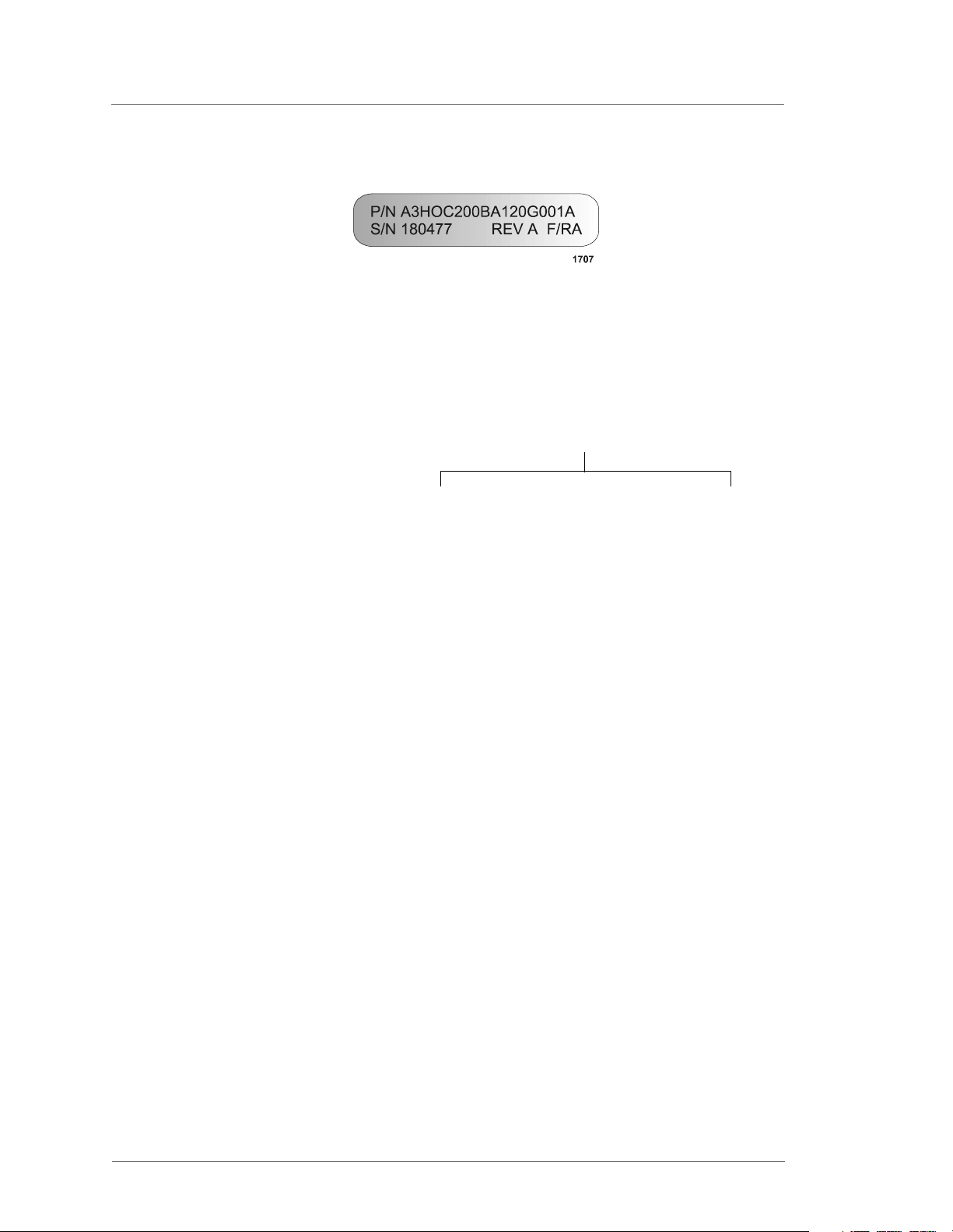
Understanding PIN Numbers and Apex Configuration
The options installed on any Apex generator (that is, the configuration of the
generator) are defined by an PIN number that is located on the serial number tag of the
generator. Figure 1-1 is an example of a serial number tag.
5708009-C 1-1
Page 14
Advanced Energy
Figure 1-1. Serial number identification tag
The PIN is a 17-position alpha-numeric that represents the configuration of your
generator and identifies the options installed on it.
®
PIN positions
Configuration positions— A 1 2 3 4 5 6 7 8 9 10 11 12 13 14 15 16 17
The “A” that precedes the PIN defines the product as an Apex generator, and it is not
counted as one of the PIN positions. The 17 PIN positions that follow the “A” are used
to identify the options installed on the generator.
Using the PIN to Locate Information in the Manual
This manual uses the PIN to help you identify the manual sections that apply to your
unit. To begin using the manual, you will need to first find and record the PIN on your
unit as you may want to refer to it frequently as you work with the manual.
Once you have located the PIN, you are ready to begin using the manual.
The manual provides two basic tools to help you use the PIN in locating correct
information for your unit.
• The next section, “Using the PIN to Identify Apex Options”, provides a complete
list of Apex features and their associated options, which are identified by each
position in the PIN number. When appropriate, it also provides cross-references
to the manual sections containing information for particular options. This table is
the easiest place to find the appropriate section of the manual when you have a
question about your unit.
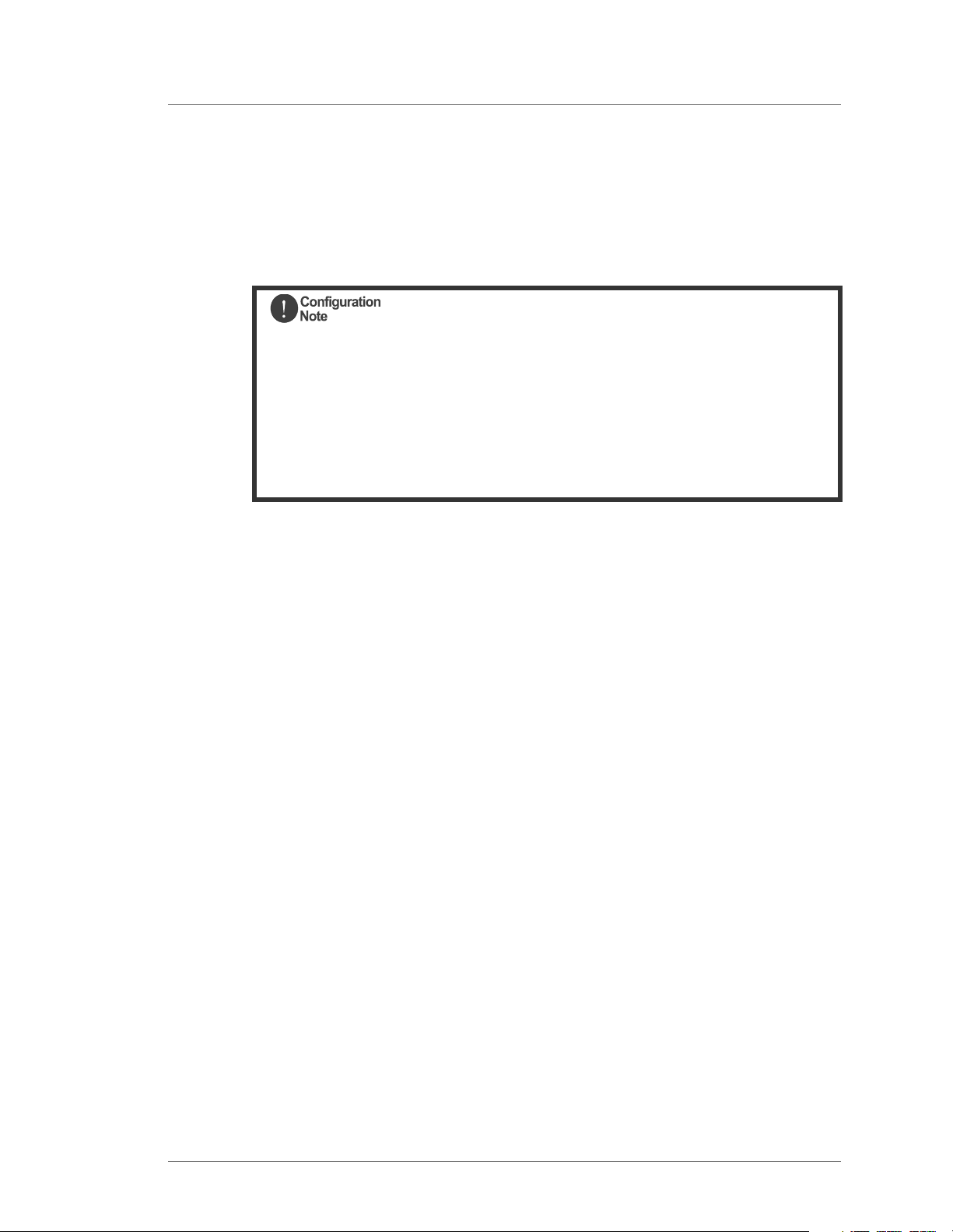
• Throughout the manual, you will also see Configuration Notes similar to the
following example. These configuration notes are placed at the beginning of many
manual sections that provide option-specific information, and they provide
information about the PIN position and option described in that section. These
1-2 5708009-C
Page 15
Apex 1 to 5.5 kW Generator
notes are best used to confirm that a particular section of the manual applies to the
option installed on a specific Apex unit. They also refer back to Table 1-1, which
provides complete configuration information
This section of the manual provides information for the:
DeviceNet option
PIN position 6, (A 1 2 3 4 5 6 7 8 9 10 11 12 13 14 15 16 17) option 2.
(When identifying the PIN position, remember that the A at the beginning of
the PIN is not counted as a position. The PIN option is the number or letter
you should look for in the specified position.)
For more information about the PIN and for a complete list of how PIN
positions correspond to Apex product options, see Table 1-1. on page 1-4.
Figure 1-2. Example configuration note
Using the PIN to Identify Apex Options
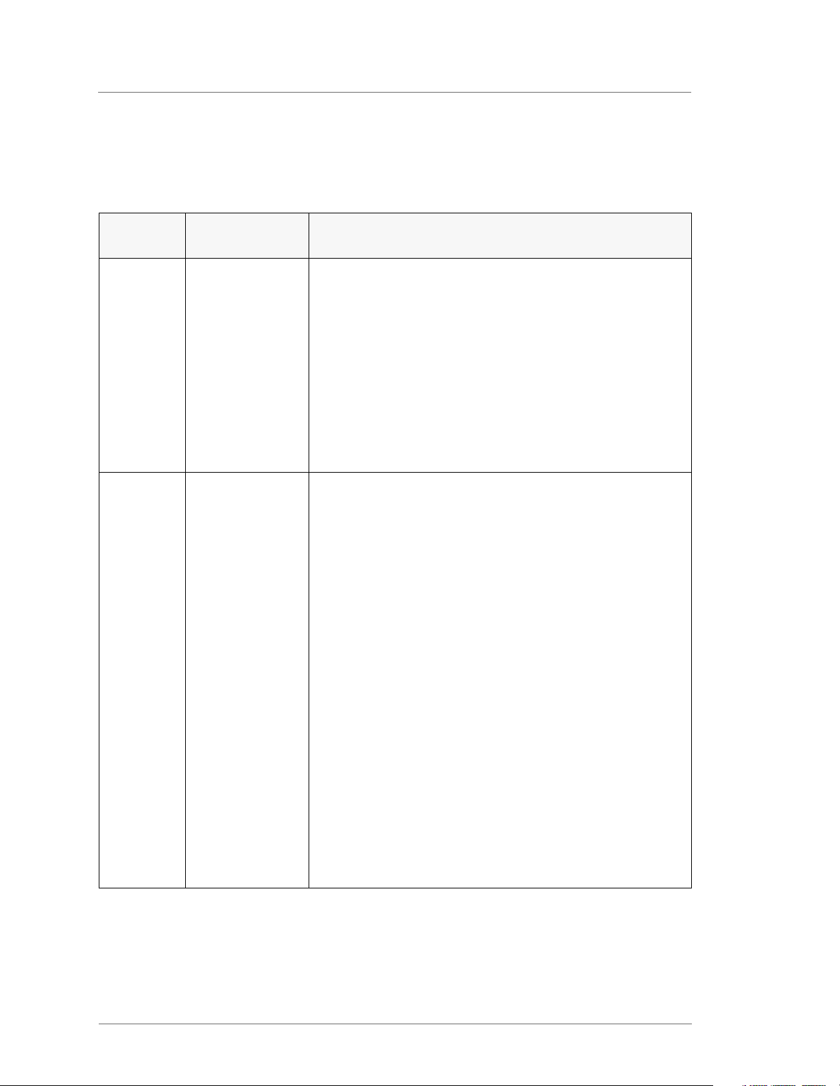
Table 1-1 shows all the options associated with each PIN position. When appropriate,
it also provides cross references to help you locate the sections of the manual
associated with your unit. For example, to find information about the output connector
on your unit, look through the table to find the PIN position associated with output
connectors, which is 11 (see row 11 of the table). Then find that position in the PIN
for your Apex unit (remember, the A at the beginning of the PIN does not count as a
position) and note the number or letter in that position. Using the right-most cell in the
correct row, identify the option installed in your unit and use the cross-reference to
locate the information on that option.
Note: Not all configurations are currently available and this manual does not cover all
currently available options. (Some options are covered in other manuals).
Therefore, not all of the options listed in the table are covered in this manual. To
make sure that you will be able to find the correct information for your unities
the manual that came with that specific unit. Contact AE for any questions
about availability of specific configurations. (For contact information, see “AE
Customer Support” on page 6-11.)
5708009-C 1-3
Page 16
Advanced Energy
®
Table 1-1. Apex PIN Positions and Associated Options
PIN
Apex Feature Options, Descriptions, and Cross-References
Position
1 Output frequency 0—N/A
1—4 MHZ, ±0.005%
2—12.56 MHz, ±0.005%
3—13.56 MHZ, ±0.005%
4—27.12 MHz, ±0.005%
5—40.68 MHz, ±0.005%
For more information on frequency and other specifications,
see “Electrical Specifications” on page 3-5.
2 Power output A—1000 W
B—1500 W
C—2000 W
D—3000 W
E—4000 W
F—5500 W
G—8000 W
H—10000 W
J—5000 W
K—1000 HALO
L—1500 HALO
M—3500 W
N—7000 W
For more information on power output and other
specifications, see “Electrical Specifications” on page 3-5.
1-4 5708009-C
Page 17
Apex 1 to 5.5 kW Generator
Table 1-1. Apex PIN Positions and Associated Options (Continued)
PIN
Apex Feature Options, Descriptions, and Cross-References
Position
3 Input voltage 0—208 V nominal, 187 to 229 Vac, 3φ, 47 to 63 Hz, with
breaker
1—400 V nominal, 360 to 440 Vac, 3
φ, 47 to 63 Hz, with
breaker
2—reserved
3—208 V nominal, 187 to 229 Vac, 3
φ, 47 to 63 Hz,
without breaker
4—400 V nominal, 360 to 440 Vac, 3
φ, 47 to 63 Hz,
without breaker
5—220,208 to 229 Vac, 1 phase, 47/63 Hz w/o breaker
For more information on input voltage and other
specifications, see “Electrical Specifications” on page 3-5.
4 Packaging A—frame mount (
≤ 5500 W)
B—frame mount with rack ears (1/2 rack) (utilities)
C—integrated rack mount
D—1/2 integrated rack mount (left)
E—1/2 integrated rack mount (right)
F—exclusive option #1
G—exclusive option #2
H—exclusive option #3
J—exclusive option #4
K—on board frame mount, opposite end LED’s
L—on board frame mount, opposite end LED’s w/4 handles
M—on board frame mount, opposite end LED’s w/2 handles
N—frame mount w/ rack ears (1/2 rack) (opposite)
5708009-C 1-5
Page 18
Advanced Energy
®
Table 1-1. Apex PIN Positions and Associated Options (Continued)
PIN
Apex Feature Options, Descriptions, and Cross-References
Position
5 Panel 0—none (on-board, frame mount)
1—integrated rack mount with blank panel
2—integrated rack mount with passive digital display
(see “Apex Status Indicators (LEDs)” on page 4-79)
3—N/A
4—exclusive option #1
For panel illustrations, see “Apex Panel Illustrations” on
page 4-80.
6 Serial I/O 0—default (RS-232 with AE Bus) (see “Host Port—RS-
232 With AE Bus” on page 4-37)
1—Multidrop RS-485 with AE Bus (Currently NOT available)
2—DeviceNet (see “Host Port—DeviceNet” on page 4-72)
3—Profibus (see “Host Port—Profibus” on page 4-58)
4—exclusive option #1
5—DeviceNet (serial)
6—exclusive option #3
7—exclusive option #2
7 Serial Port 2 0—default (no secondary serial port)
1—RS 232
2—RS 485
1-6 5708009-C
Page 19

Apex 1 to 5.5 kW Generator
Table 1-1. Apex PIN Positions and Associated Options (Continued)
PIN
Apex Feature Options, Descriptions, and Cross-References
Position
8 User port options A—no User port
B—25-pin APEX standard (see “25-Pin Apex Standard
User Port” on page 4-2)
C—25-pin custom RFG compatible
D—15-pin, exclusive option #2 (see “15-Pin User Port
(Exclusive—Option D)” on page 4-16)
E—15-pin, exclusive option #3 (see “15-Pin User Port
(Exclusive—Option E)” on page 4-26)
F—N/A
G—exclusive option #4
9 Output
A—50
impedance
B—exclusive option #1
C—exclusive option #2
D—exclusive option #5
Ω
10 On-board RF
output connector
location
E—exclusive option #6
F—exclusive option #3
G—exclusive option #4
H— exclusive option #7
J—exclusive option #8
0—opposite end from water connections
1—utilities end (near water connections)
5708009-C 1-7
Page 20
Advanced Energy
®
Table 1-1. Apex PIN Positions and Associated Options (Continued)
PIN
Apex Feature Options, Descriptions, and Cross-References
Position
11 Output connector 0—exclusive option #1
1—7/16 connector)
2—SQS
connector
3—LC connector
4—HN
5—N
6—exclusive option #2
For further information see “Connecting Output Power” on
page 5-5.
12 RF measurement 0—directional coupler
1—V/I sensor
13 AC power input A—ODU connector (see “ODU Connector” on page 5-7)
B—Non-terminated 3 m, 4-conductor, shielded pigtail
(see “NonTerminated, four-Conductor Pigtail” on page 5-8)
C—Non-terminated 12
“NonTerminated, four-Conductor Pigtail” on page 5-8)
D—Harting Type Han-Q (see “Harting Type Han-Q
Connector” on page 5-9)
E—4-terminal, stud mount
F—15´ 4-conductor, with a Hubbell CS8365C plug
G—5´ Harting
H—Term 3m, 4 cond, shielded pigtail Marinco 3015P
J—5’ terminated, 4 conductor, SH with contact LS1 BF.F6 5+PE (30A)
K—ODU connector with 20 degree rotation
L—Harting Type Han-Q (16A) rotated 180 degrees
M—6’,4 conductor with #10 ring lugs on each wire
14 Pulsing 0—no pulsing
1—pulse (see “Understanding and Setting Up Pulsing
Output” on page 5-13)
′, 4-conductor, pigtail (see
1-8 5708009-C
Page 21

Apex 1 to 5.5 kW Generator
Table 1-1. Apex PIN Positions and Associated Options (Continued)
PIN
Position
15 CEX 0—default (no CEX)
16 Water fitting
17 Custom
Apex Feature Options, Descriptions, and Cross-References
1—CEX add (see “To Use the Common Exciter (CEX)
Feature (optional)” on page 5-12)
2—CEX w/1 Meter Cable (see “To Use the Common
Exciter (CEX) Feature (optional)” on page 5-12)
0—default to 3/8 BSP female (metric threads)
threads
configuration
1—3/8 NPT female
2—3/8 BSP to 1/2" NPT
For information on connecting the water, see “Connecting
Cooling Water” on page 5-4.
A—standard configurations
B—exclusive option #1
C—exclusive option #2
D—exclusive option #3
E—exclusive option #4
INTERPRETING THE MANUAL AND UNIT LABELS
The following sections provide information to help you interpret the use of type in the
manual as well as frequently used graphics in the manual. It also provides a reference
chart to help you understand the labels that may be used on the Apex unit.
Type Conventions
To help you quickly find what is being discussed, the manual presents certain words
and phrases in type that are different from the rest of the text. We use the following
type conventions:
• Pin and signal names appear in capitalized italics (DUTY CYCLE.A).
• Labels that are on the unit (switches, indicators, etc.) generally appear in boldface
capital letters (MODIFY); however they appear as you see them on the unit.
Exceptions are port names, which simply begin with a capital letter (User port).
• Commands (162) and command names (setpoint) appear in boldface lowercase
letters.
• Italic refers to any new or unfamiliar term.
5708009-C 1-9
Page 22
Advanced Energy
®
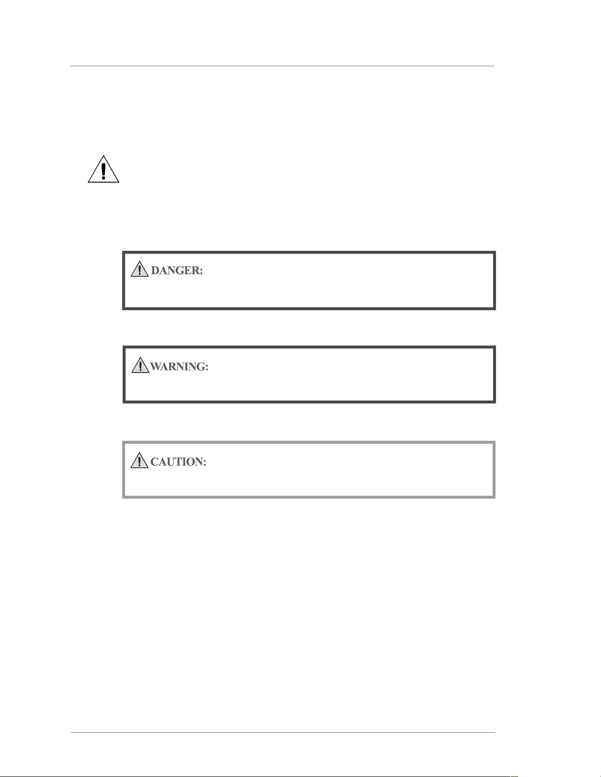
Icons (Symbols)
This symbol represents important notes concerning potential harm to
people, this unit, or associated equipment. It is found whenever
needed in the manual.
We include this symbol in Danger, Warning, and Caution boxes to identify specific
levels of hazard seriousness.
This box identifies hazards that could result in severe personal injury or
death.
This box identifies hazards or unsafe practices that could result in
personal injury.
This box identifies hazards or unsafe practices that could result in
product or property damage.
The following symbols could appear on labels on your unit.
1-10 5708009-C
Page 23
Apex 1 to 5.5 kW Generator
Capacitor charge
Hazardous Voltage
Short circuit protected
High voltage
Protective earth ground
Earth ground
CE label
5708009-C 1-11
Page 24
Advanced Energy
Non-ionizing radiation
Hot surface
Warning (refer to manual)
®
NRTL
SAFETY
Do not attempt to install or operate this equipment if you have not first acquired proper training.
• Ensure that this unit is properly grounded.
• Ensure that all cables are properly connected.
• Verify that input line voltage and current capacity are within specifications before
turning on the power supplies.
• Use proper ESD precautions.
• BE CAREFUL AROUND THIS EQUIPMENT
PRODUCT SAFETY/COMPLIANCE
Certain options of the Apex have been tested for and comply with the following
Directives and Standards.
1-12 5708009-C
Page 25
Apex 1 to 5.5 kW Generator
Directives and Standards
The following tables list the Electromagnetic Compatibility (EMC) and Safety
directives and standards.
Table 1-2. Electromagnetic Compatibility (EMC)
Directive Description
89/336/EEC EC Council directive on the approximation of the laws of the
Member States relating to electromagnetic compatibility (EMC
Directive).
47 CFR Part 18 Code of Federal Regulations - Limits and Methods of
Measurement of Radio Interference Characteristics of Industrial,
Scientific, and Medical Equipment.
EN 50082-2 Electromagnetic Compatibility (Generic Immunity Standard—
Industrial)
EN 55011 Limits and Methods of Measurement of Radio Disturbance
Characteristics of Industrial, Scientific, Medical (ISM) Radio
Frequency Equipment (Class A, Group 2) (CISPR 11).
Table 1-3. Safety
Directive Description
73/23/EEC EC Council directive on the harmonization of the laws of the
Member States relating to electrical equipment designed for use
within certain voltage limits (LVD - Low Voltage Directive).
SEMI S2-0200 Safety Guidelines for Semiconductor Manufacturing Equipment
UL 1012 Power units other than class 2
EN 50178 Electronic Equipment For Use In Electrical Power Installations
CSA C22.2
No. 107.1-95
This device must be installed and used only in compliance with the standards listed in
addition to VDE 0113, EN 60204 (IEC 204), and applicable requirements.
General Use Power Supplies—Industrial Products
5708009-C 1-13
Page 26

Advanced Energy
®
Certification
Certain options of this product are certified by:
• Canadian Standards Association (CSA) (NRTL/C)
• CE marking is self addressed by AE Compliance Engineering
• EMC measurements verified by TÜV Product Services
For more information, refer to the letter of conformance (US) or declaration of
conformity (EU) accompanying the product.
1-14 5708009-C
Page 27
Apex 1 to 5.5 kW Generator
INSTALLATION REQUIREMENTS
In order for proper installation to be completed on the Apex generator, please take
note of the following warning boxes and the information contained in them. By
meeting all the criteria in these boxes, proper installation of the Apex generator will be
accomplished.
Operating and maintenance personnel must receive proper training
before installing, troubleshooting, or maintaining high-energy electrical
equipment. Potentially lethal voltages could cause death, serious
personal injury, or damage to the equipment. Ensure that all appropriate
safety precautions are taken.
RISK OF DEATH OR BODILY INJURY. Disconnect and LOCK-OUT/TAGOut all sources of input power before working on this unit or anything
connected to it.
5708009-C 1-15
Page 28

Advanced Energy
®
Conditions of Use
To be in compliance with the stated directives and standards, you must meet the
following conditions of use.
• This device must be used in an overvoltage category II installation only.
• Before making any other connection, connect the auxiliary Protective Earth
ground conductor on the rear panel.
• Use only a shielded cable on the input power connector.
• Use only a shielded power cable on the output power connector.
• Install and operate this device only in a pollution degree 2 or better environment,
which means an indoor location such as a computer room, office, or factory floor
where only non-conductive pollution occurs during operation. Occasionally, a
temporary conductivity caused by condensation occurs when the device is not
operating.
• Non-standard connectors for input and/or output power must be inaccessible to
the user.
• If your unit does not have a circuit breaker, install and operate it with a circuit
breaker on the ac input to provide over current protection. The circuit breaker
must have a trip value as specified in the line current section of Table 3-2. on
page 3-5.
1-16 5708009-C
Page 29

2Theory
GENERAL DESCRIPTION
The Apex™ product line consisting of generators and delivery system products
defined by a matrix of features and capabilities that can be easily custom configured to
specific requirements and applications.
Apex 1 to 5.5 kW Generator
Chapter
Chapter
2
The Apex products can be configured to three basic package styles. The Apex
products may be configured with integrated SwitchMatch
sophisticated VI sensor instrumentation in place of standard power measurement. The
Apex products feature a powerful microprocessor for flexible and accurate operation.
The microprocessor also facilitates the addition of one of several optional serial
communications protocols in addition to the standard AE Bus host port. Several
parallel digital/analog I/O choices are also available. Apex products are designed to be
used in clean room environments and are water cooled.
Other optional features include high repetition rate, variable duty cycle pulsing and
common exciter (CEX) phase lock operation.
FUNCTIONAL DESCRIPTION
In the following section, an overview of the functional description about the Apex
products is discussed. Covered in the section is regulation, cooling, interlock, optional
water solenoid, grounding and protection. These general descriptions are important to
the User since they allow the User to become familiar with the functions of the Apex
generator.
Regulation
™
matching networks and
The Apex generator regulates on forward power, delivered power, or bias voltage
measured at the output of the generator. Mode selection is made through a designated
pin in the interface connector or by receiving a command through a digital interface
option.
Cooling
Apex generators are water-cooled only.
5708009-C 2-1
Page 30

Advanced Energy
®
Interlock
The Apex generator provides a system interlock connection through the User port.
The RF output connector is also interlocked by a series switch that is part of the
system interlock.
Optional Water Solenoid
The Apex generator provides water solenoid control circuitry that can be accessed
through a connector on the rear of the generator. When an optional water control
solenoid is connected to the water solenoid control circuitry, the Apex generator
controls operation of the solenoid and water flow. This feature minimizes
condensation in the generator when the RF output is off and cooling water is still
circulating through the generator.
Grounding
The Apex generator has two holes located on the rear panel to attach the system RF
ground to. One is a tapped M-6 hole, the other is a 5/16
may be used to provide an appropriate ground. Select the appropriate hole depending
on whether you use metric or American fasteners.
Protection
The Apex generator protects itself from damage from the following conditions.
• Any unmatched load condition at the generator output. Output power fold-back
• Any internal over current condition not directly related to the output load
• Excessive internal temperature. (This condition may be caused by lack of proper
• Any combination of input ac line phase drop out.
• Input line brown-out (under voltage) or over voltage.
• Any User/ port pin shorted to chassis or another port pin.
″ x 18 tapped hole. Either hole
(limiting) occurs as required by the generator protection circuits.
condition as protected by current limiting or fuse.
cooling water flow, excessive ambient operating temperature, or other causes.)
THEORY OF OPERATION
In this section a bock diagram is designed to help the User understand the process by
which the Apex generator works. Following the diagram is an explanation of the
diagram in a table to help the User utilize the Apex unit as well. Figure 2-1 and Table
2-1 describe the basic operation of the Apex generator.
2-2 5708009-C
Page 31

Apex 1 to 5.5 kW Generator
(2) Driver/ Exciter
(3)
RF
Amplifiers
(1)
User
Port
Host
Port
Analog
I/O
(5)
Digital
Controller
(6)
Sensor
Electronics
Figure 2-1. Theory of operation block diagram
(4)
RF
Measure
RF Output
Table 2-1. Block Diagram Explanation
(1) User port (Analog
This section provides user interface and CEX functions.
I/O)
(2) Driver/Exciter This section generates power at the designated output frequency
to drive the main RF sections.
(3) RF Amplifier This section generates RF power.
(4) RF Measurement This section samples the output signal and sends it to the sensor
electronics.
(5) Digital
Controller
This section is the main processor and data acquisition section. It
also provides host communications through an RS-232 port.
(6) Sensor Electronics This section detects RF samples and sends them to the
microprocessor.
5708009-C 2-3
Page 32

Advanced Energy
®
2-4 5708009-C
Page 33

3Specifications
This chapter lists the specifications of the Apex generator in the following sections:
•“Physical Specifications” on page 3-1
•“Electrical Specifications” on page 3-5
•“Cooling Specifications” on page 3-10
•“Environmental Specifications” on page 3-14
In some cases, specifications for all Apex units are the same, but in other cases, the
unit specifications vary depending on the options installed on the unit. In such cases,
the manual refers to the PIN position that defines those specifications, lists the PIN
and configuration options that are available, and when appropriate, provide cross
references to more information on those specific options. For more information on
using the PIN to identify information applicable to your unit, see “Using this Manual
to Find Information for Your Generator” on page 1-1.
Apex 1 to 5.5 kW Generator
Chapter
Chapter
3
PHYSICAL SPECIFICATIONS
Table 3-1 describes the physical specifications of the Apex generator. In some cases,
the specifications for all 1 to 5.5 kW Apex units are the same, but in other cases, the
unit specifications vary depending on the options installed. In such cases, the
specification table refers to the PIN position that defines those specifications, lists the
PIN and configuration options that are available and, when appropriate, provides cross
references to more information on those options. For more information on using the
PIN to identify information applicable to your Apex unit, see “Using this Manual to
Find Information for Your Generator” on page 1-1.
5708009-C 3-1
Page 34

Advanced Energy
®
Table 3-1. Physical Specifications
Description PIN Option—Specification
Packaging
Note: Varies according to the
option defined by PIN
position 4.
A—frame mount (
≤ 5500 Watts)
B—frame mount w/rack ears (1/2 rack) (rack ears on same end of the unit as the water connectors)
C—integrated rack mount
D—1/2 dual integrated rack mount (left)
E—1/2 dual integrated rack mount (right)
F—exclusive option #1
G—exclusive option #2
H—exclusive option #3
J—exclusive option #3
K—on-board frame mount, opposite end LEDs
L—on-board frame mount, opposite end LEDs, with 4
handles
M—on board frame mount, opposite end LEDs, with 2 handles
N—frame mount with rack ears (1/2 rack) (opposite end from water connectors)
Size 13.34 cm (H) x 21.6 cm (W) x 48.47 cm (D)
″ (H) x 8.5″ (W) x 19.19″ (D) See Figure 5-1 on
5.25
page 5-3
Note: The size of the unit depends on configuration of
your Apex unit. These dimensions are for the
drawing in Chapter 5. See Figure 5-1 on
page 5-3.
Weight 18.2 kg (40 lbs.) Clearance No special requirements
3-2 5708009-C
Page 35

Apex 1 to 5.5 kW Generator
Table 3-1. Physical Specifications (Continued)
Description PIN Option—Specification
AC power input connector
Note: Varies according to the
option defined by PIN
position 13.
A—ODU connector (see “ODU Connector” on
page 5-7)
B—Non-terminated 3 m, 4-conductor, shielded pigtail
(see “NonTerminated, four-Conductor Pigtail” on
page 5-8)
C—Non-terminated 12¢, 4-conductor, pigtail (see
“NonTerminated, four-Conductor Pigtail” on page 5-8)
D—Harting Type Han-Q (see “Harting Type Han-Q
Connector” on page 5-9)
E—4-terminal, stud mount
F—15´ 4-conductor, with a Hubbell CS8365C plug
G—5´ Harting
H—Term 3m, 4 cond, shielded pigtail Marinco 3015P
J—5’ terminated, 4 conductor, SH with contact LS1
BF.F6 5+PE (30A)
K—ODU connector with 20 degree rotation
L—Harting Type Han-Q (16A) rotated 180 degrees
RF output connector
Note: Varies according to the
option defined by PIN
position 11.
RF Connector location
Note: Varies according to the
option defined by PIN
position 10.
M—6’,4 conductor with #10 ring lugs on each wire
0—exclusive option #1
1—7/16 connector (see “Connecting Output Power” on
page 5-5)
2—SQS‘connector (see “Connecting Output Power” on
page 5-5)
3—LC connector (see “Connecting Output Power” on
page 5-5)
4—HN (see “Connecting Output Power” on page 5-5)
5—N (see “Connecting Output Power” on page 5-5)
6—exclusive option #2 0—opposite end from water connections
1—utilities end (near water connections)
5708009-C 3-3
Page 36

Advanced Energy
®
Table 3-1. Physical Specifications (Continued)
Description PIN Option—Specification
Water control connectors Switchcraft™ #L712A
User port (analog I/O) connector
Note: Varies according to the
option defined by PIN
position 8.
Host port (serial I/O) connector
Note: Varies according to the
option defined by PIN
position 6.
A—no analog port
B—25-pin APEX standard (see “25-Pin Apex Standard
User Port” on page 4-2)
C—25-pin custom RFG compatible
D—15-pin, exclusive option #2 (see “15-Pin User Port
(Exclusive—Option D)” on page 4-16)
E—15-pin, exclusive option #3 (see “15-Pin User Port
(Exclusive—Option E)” on page 4-26)
F—N/A
G—exclusive option #4
0—9-pin, shielded, female, subminiature-D (see “Host
Port—RS-232 With AE Bus” on page 4-37)
1—9-pin, shielded, female, subminiature-D (Currently NOT available)
2—5-pin, male, Lumberg RSF 5/0.5 or Turck FS 4.5
(see “Host Port—DeviceNet” on page 4-72)
3—9-pin, shielded, female, subminiature-D (see “Host
Port—Profibus” on page 4-58)
4—exclusive option #1
5—5-pin, male, Lumberg RSF 5/0.5 or Turck FS 4.5
6—9-pin, shielded, female, subminiature-D
7—exclusive option #2
CEX connector Female LIMO#EPL.00.250.NTN
Coolant connectors
Note: Varies according to the
option defined by PIN
0—3/8 BSP female
1—3/8 NPT adapters (adapters from 3/8 BSP female
threads in the manifold)(increases unit length)
position 16.
2—3/8 BSP to 1/2
″ NPT
For information on connecting the water, see
“Connecting Cooling Water” on page 5-4.
3-4 5708009-C
Page 37

Apex 1 to 5.5 kW Generator
Table 3-1. Physical Specifications (Continued)
Description PIN Option—Specification
Panel
Note: Varies according to the
option defined by PIN
position 5.
RF measurement option
Note: Varies according to the
option defined by PIN
position 12.
0—on-board frame mount
1—Integrated rack-mount with blank panel
2—Integrated rack-mount with passive digital display
3—Integrated rack-mount with active digital display
4—exclusive option #1 0—Coupler
1—V/I probe
ELECTRICAL SPECIFICATIONS
Table 3-2, Table 3-3, and Table 3-4 describe the input power, output power, and other
electrical specifications for the Apex generator. In some cases, the specifications for
all 1 to 5.5 kW Apex units are the same, but in other cases, unit specifications vary
depending on the options installed. In such cases, the specification table refers to the
PIN position that defines those specifications, lists the PIN and configuration options
that are available and, when appropriate, provides cross references to more
information on those options. For more information on using the PIN to identify
information applicable to your Apex unit, see “Using this Manual to Find Information
for Your Generator” on page 1-1.
Input Power Specifications
Table 3-2 describes the input power specifications for the Apex generator.
Table 3-2. Input Power Specifications
Description PIN Option and Specification
Line voltage
Note: Varies according to the
option defined by PIN
position 3.
5708009-C 3-5
0—208 V nominal, 187 to 229 Vac, 3
1—400 V nominal, 360 to 440 Vac, 3φ
2—n/a
3—208 V nominal, 187 to 229 Vac, 3
4—400 V nominal, 360 to 440 Vac, 3φ
φ
φ
Page 38

Advanced Energy
Table 3-2. Input Power Specifications (Continued)
Description PIN Option and Specification
Line frequency 47 to 63 Hz
®
Line current Typical A/
208 Vac nominal input (PIN position 3, options 0 and 3)
• 1500 W/13.56 MHz—9 A/
• 3000 W/13.56 MHz—14 A/
• 5500 W/13.56 MHz—25 A/
Typical A/
400 Vac nominal input (PIN position 3, option 1)
• 3000 W/13.56 MHz—9 A/
• 5500 W/13.56 MHz—15 A/
φ and circuit breaker rating for units with
φ and circuit breaker rating for units with
Output Electrical Specifications
Table 3-3 describes the output specifications for the Apex generator.
Table 3-3. Output Specifications
Description PIN Option and Specification
φ; 15 A breaker
φ; 25 A breaker
φ; 40 A breaker
φ; 15 A breaker
φ; 25 A breaker
Regulation modes • Forward power
• Load power
• External feedback (dc bias, for example)
Output frequency
Note: Varies according to the
option defined by PIN
position 1.
0—N/A
3—13.56 MHZ, ±0.005%
3-6 5708009-C
Page 39

Apex 1 to 5.5 kW Generator
Table 3-3. Output Specifications (Continued)
Description PIN Option and Specification
Full-rated output power
(Minimum into a 50
Ω, non-
reactive load)
Note: Varies according to the
option defined by PIN
position 2.
Output impedance
Note: Varies according to the
option defined by PIN
position 9.
A—1000 W
B—1500 W
C—2000 W
D—3000 W
E—4000 W
F—5500 W
J—5000 W
K—1000 W high accuracy low output (HALO)
L—1500 W HALO minimum into a 50
Ω, non-reactive
load
M—3500 W
A—50
Ω
B—exclusive option #1
C—exclusive option #2
D—exclusive option #5
Delivered power into 2:1 VSWR loads
Note: Varies according to the
option defined by PIN
position 2.
Delivered power into 3:1 VSWR loads
Note: Varies according to the
option defined by PIN 2.
E—exclusive option #6
F—exclusive option #3
G—exclusive option #4
H—exclusive option #7
J—exclusive option #8
B—1.5kW = 1125W
D—3kW = 2000W
F—5.5kW = 3350W
B—1.5kW = 650W
D—3kW = 1200W
F—5.5kW = 1900W
5708009-C 3-7
Page 40

Advanced Energy
®
Table 3-3. Output Specifications (Continued)
Description PIN Option and Specification
Output protection—Apex generators sense and employ several parameters for protection
Reflected power limit 20% of maximum forward power for units rated for less
than 5500 W. 1000 W for 5500 W units. (PIN position 2
defines the maximum forward power rating for the unit.)
Dissipation limit Maximum PA dissipation—non-latching alarm LED
Low/high line bus Bus voltage outside spec window—latching alarm LED
Over-temperature Over-temp condition—latching alarm LED preceded by
non-fault warning (user setting).
Output power range All generators except the HALO will allow setpoints
between 1% and 100% of full scale. The exception is the
HALO 1.5k generator depicted by “L” in position 2 of the
PIN number. This allows setpoints from 5 watts to 1500
watts.
Output power regulation accuracy
Into 50
Ω non-reactive load • ± 1% of setpoint or ± 0.1% of full-rated output,
whichever is greater (all PIN position 2 options but K
and L)
≤ ±1% of setpoint or 0.25 W, whichever is greater
•
(PIN position 2, option K & L)
Into 3:1 VSWR nonreactive load
± 3% of setpoint (load power regulation), over all load
phase angles, or ± 0.25% of full-rated output, which ever is
greater
Load regulation as a function of line regulation
Less than 0.1% change in output power for 10% change in
ac line voltage
Load regulation as a function of temperature—(performance in accordance with the output
power regulation accuracy)
Ambient air temperature
°C to +40°C
+5
range
Cooling water temperature
°C to +35°C
+5
range
Spurious outputs—Referenced to fundamental signal at full-rated output when operated in a
Ω non-reactive load
50
Harmonic related -40 dBc Non-harmonic related -50 dBc
3-8 5708009-C
Page 41

Apex 1 to 5.5 kW Generator
Table 3-3. Output Specifications (Continued)
Description PIN Option and Specification
Warm up Approximately 2 s from ac-on to RF-on RF On Response time < 7 ms (6.4 ms typical) Turn-off/decay time 10 µs until output decays to 1% of maximum rated value.
Power repeatability
Power cycles, standard options
Note: Applies to units with
options 0 through 5 in PIN
position 6.
Power Cycles with DC heating option
Note: DC heating option applies
only to units with option 6
or 7 in PIN position 6.
≤ 0.5% over time for same generator for setpoints
> 500 W. 1% generator to generator as measured against
AE calorimetric standard
6 million cycles, 0 to full power into a matched load
360 kilocycles, 0 to full power into high dissipation load
30 million cycles, 0 to full power into a matched load
5 million cycles, 0 to full power into high dissipation load
Other Electrical Specifications
Table 3-4 describes the other electrical specifications for the Apex generator.
Table 3-4. Other Electrical Specifications
Description PIN Option and Specification
Efficiency (line to load) 60%, typical @ full-rated power, nominal line Power factor > 0.96 Maximum leakage current 3.5 mA Master - Slave / CEX (The Apex generator automatically locks the RF output signal phase
to the common exciter—CEX—input signal phase when the following conditions are met.)
Phase relationship (RF output inphase with the CEX input signal)
5708009-C 3-9
° ± 5°
0
Page 42

Advanced Energy
Table 3-4. Other Electrical Specifications (Continued)
Description PIN Option and Specification
CEX In • Required signal amplitude range of +2 dBm to +10
®
dBm
• Generator operating frequency
• Input impedance of 50
CEX Out • Output signal amplitude range of +3 dBm to +7
dBm
• Generator operating frequency
• Output impedance of 50
Ω, less than 1.5:1 VSWR
±0.005%
±0.005%
Ω, less than 1.5:1 VSWR
COOLING SPECIFICATIONS
Table 3-5 describes the cooling specifications for the Apex generator.
Do not use de-ionized water for cooling purposes. De-ionized water
causes both corrosion and erosion of cooling manifolds.
Table 3-5. Cooling Specification
Description Specification
Temperature +35
Flow rate
Note: Varies according to the
option defined by PIN
position 2.
Pressure
Minimum pressure differential (supply to drain) required to achieve specified minimum flow rates)
3-10 5708009-C
°C (+95°F)
Note: Maximum water temperature at minimum flow rate
and maximum ambient air temperature (+40
≤ 3kW 7.6 1pm (2 gpm)
For
For > 3kW 11.4 1pm (3 gpm)
≤ 3kW 0.9 Bar (13psi)
For
For > 3kW 2 Bar (29 psi)
° C).
Page 43

Apex 1 to 5.5 kW Generator
Table 3-5. Cooling Specification (Continued)
Description Specification
Maximum pressure
6.9 Bar (100 psi)
rating
Heat removal • For 1.5 kW, 3410 BTU/hour, 1000W at full rated
output power
• For 3 kW, 6825 BTU/hour, 2000W at full rated output
power
• For 5.5 kW, 12,500 BTU/hour, 3660W at full rated RF
output power
Contaminates The following specifications are recommended for the
water used to cool the Apex generator:
• pH between 7 and 9
• Total chlorine < 20 ppm
• Total nitrate < 10 ppm
• Total sulfate < 100 ppm
• Total dissolved solids < 250 ppm
• Total hardness expressed as calcium carbonate
equivalent less than 250 ppm
• Specific resistivity of 2500
Ω/cm or higher at 25°C
• Total dissolved solids (TDS) as estimated by the
following:
TDS
≤ 640,000
specific resistivity (Ω/cm)
5708009-C 3-11
Page 44

Advanced Energy
®
Graphical Representations of Flow Rate
The following graph shows how flow (gpm) lessens as the pressure (psi) drops.
6
5.2
5
4
GPM
3
x
n
Flow (GPM)
2
1
0.1
0
0102030405060708090
0 PSI y xn,
Pressure drop (PSI)
Figure 3-1. Flow Rate vs. Pressure Drop
82.83
3-12 5708009-C
Page 45

Apex 1 to 5.5 kW Generator
The following graph shows how Water Flow vs. Inlet Temp for all three Apex Units.
It represents the inlet temperature rising as flow rate increases.
40
35
30
25
20
15
10
Inlet Temp - Degrees C
5
0
0 0.5 1 1.5 2 2.5 3
Water Flow vs Inlet Temp
Apex Generator
5513
3013
1513
Flow - gpm
Figure 3-2. Water flow vs. Inlet Temperature
Note: 5513 = 5500W and 13.56 MHz
3013 = 3000W and 13.56 MHz
1513 = 1500W and 13.56 MHz
5708009-C 3-13
Page 46

Advanced Energy
®
ENVIRONMENTAL SPECIFICATIONS
Table 3-6 and Table 3-7 provide climatic and other environmental specifications for
the Apex generator.
Table 3-6. Climatic Specifications
Temperature Relative Humidity Air Pressure
Operating
Class 3K3
°C to +40°C
5
°F to +104°F
+41
Class 3K2
10% to 85%
1
+2 g/m3 to +25 g/m
Class 3K3
80 kPa to 106 kPa
3
800 mbar to 1060 mbar (approximately 2000 m above sea level)
Storage
Class 1K4
°C to +55°C
-25
°F to +131°F
-13
Class 1K3
5% to 95%
3
+1 g/m
to +29 g/m
Class 1K4
80 kPa to 106 kPa
3
800 mbar to 1060 mbar (approximately 2000 m above sea level)
Transportation
Class 2K3
°C to +70°C
-25
°F to +158°F
-13
Class 2K3
2
95%
+60 g/m
3 3
Class 2K3
66 kPa to 106 kPa
660 mbar to 1060 mbar (approximately 3265 m above sea level)
1
Non-condensing
2
Maximum relative humidity when the unit temperature slowly increases, or when the unit
temperature directly increases from -25°C to +30°C
3
Maximum absolute humidity when the unit temperature directly decreases from +70°C to
+15°C
Table 3-7 shows other environmental specifications for the Apex generator.
Table 3-7. Environmental Specifications
Description Specification
Overvoltage Category II Pollution Degree 2
3-14 5708009-C
Page 47

Apex 1 to 5.5 kW Generator
4Interfaces and Indicators
This chapter contains information on the Apex communication interfaces and status
indicators (LEDs). It also contains representative drawings of the front and rear panels
of the unit. The chapter is divided up into sections as follows.
• The first section of the chapter, “Apex User Port Options” on page 4-2, contains
a subsection for each of the User port options available with the Apex 1 to 5.5 kW
generator. These subsections are:
–“25-Pin Apex Standard User Port” on page 4-2
–“15-Pin User Port (Exclusive—Option D)” on page 4-16
–“15-Pin User Port (Exclusive—Option E)” on page 4-26
Chapter
Chapter
4
• The second section of the chapter, “Apex Host Port Options” on page 4-37,
contains a subsection for each of the serial Host port options available with the
Apex 1 to 5.5 kW generator. These subsections are:
–“Host Port—RS-232 With AE Bus” on page 4-37
–“Host Port—Profibus” on page 4-58
–“Host Port—DeviceNet” on page 4-72
• The third section of the chapter, “Apex Status Indicators (LEDs)” on page 4-79,
contains information on interpreting the LED indicators that appear on some Apex
units.
• The final section of the chapter, “Apex Panel Illustrations” on page 4-80, provides
illustrations of Apex front and rear panels.
Not all of these sections apply to any one Apex unit. To identify the sections that
apply to your unit, see “Using this Manual to Find Information for Your Generator”
on page 1-1. Each of the option-specific sections of this chapter also contain PIN
configuration notes, which help you confirm whether or not a particular section
applies to your unit.
5708009-C 4-1
Page 48

Advanced Energy
®
APEX USER PORT OPTIONS
The following sections provide information for each of the User port options available
with the 1 to 5.5 kW Apex generator. These options are:
•“25-Pin Apex Standard User Port” on page 4-2
•“15-Pin User Port (Exclusive—Option D)” on page 4-16
•“15-Pin User Port (Exclusive—Option E)” on page 4-26
Not all of these sections apply to any one Apex unit. To identify the section that
applies to your unit, see “Using this Manual to Find Information for Your Generator”
on page 1-1. Each of these sections also contains a PIN configuration note, which will
help you confirm whether or not a particular section applies to your unit.
25-Pin Apex Standard User Port
The following section describes the Apex standard 25-pin User port. To determine if
your Apex unit has this interface, use the configuration PIN from your Apex unit and
the following Configuration Note.
This section of the manual provides information for the:
Apex standard 25-pin User port option
PIN position 8, (A 1 2 3 4 5 6 7 8 9 10 11 12 13 14 15 16 17) option B.
(When identifying the PIN position, remember that the A at the beginning of
the PIN is not counted as a position. The PIN option is the number or letter
you should look for in the specified position.)
For more information about the PIN and for a complete list of how PIN
positions correspond to Apex product options, see Table 1-1. on page 1-4.
This User port is the standard option.
The User port uses a 25-pin, shielded, female, subminiature-D connector.
Figure 4-1. User Port connector 25 Pin APEX Standard
4-2 5708009-C
Page 49

Apex 1 to 5.5 kW Generator
Unless otherwise specified, all analog signals are 0 to 10 V while all digital signals are
5 to 24 V, opto-coupled (open-collector signals with return lines non-referenced to
ground).
Ground/Return lines are floating and need to be connected as close to the system as possible.
SATISFYING MINIMAL REQUIREMENTS FOR THE 25-PIN USER PORT
Regardless of whether you are controlling and monitoring the generator through the
User port or through another port, two User port signals must be satisfied for the Apex
unit to be operational: RF PWR ON (pin 4) and INTERLOCK LOOP (pins 10 and 23).
In other words, even if you are controlling the generator through the serial port
interface, the RF signal must be enabled and the interlock satisfied.
Note: If you are controlling your generator through a port other than the User port,
make sure that the control mode is set appropriately (to host mode to control
through the Host port, for example) before powering up the unit. The control
mode can be set through a Host port command.
If you are not using the User port to control or monitor the unit, you can use a
“dummy” or “cheater” plug to satisfy these two signals, thereby ignoring the User
port. To make such a plug, solder two jumpers on a mating connector: one between
pins 4 and 9 to satisfy the RF PWR ON signal and one between pins 10 and 23 to
satisfy the INTERLOCK LOOP signal. To determine the physical location of these pin
numbers on the User port, see Figure 4-1 on page 4-2.
If desired, you can add an emergency off switch in series with the RF PWR ON signal
(pin 4) or tie your system interlocks in series with the generator INTERLOCK LOOP
signal (pins 10 and 23) by following the connections for those pins described in “Pin
Descriptions for the 25-Pin User Port” on page 4-3 and “Wiring Diagrams for the
Standard 25-Pin User Port” on page 4-9.
INTERFACE CABLING REQUIREMENTS FOR 25-PIN USER PORT
The cable used to connect the Apex generator’s User port to the system controller
must be a shielded, 25-wire I/O cable. Twisted-pair wiring may be used but is not
mandatory. Signal losses should be minimized by keeping the cable length as short as
possible. The maximum recommended cable length between the generator and the
controller is 10 meters (33´). To minimize interference from adjacent electrical
equipment, the EMI shield in the cable must be terminated to the metal shells of the
cable’s connectors. Additionally, the chassis of the Apex generator must be tied to a
local earth ground through an adequately sized copper grounding strap.
PIN DESCRIPTIONS FOR THE 25-PIN USER PORT
Table 4-1 provides the connector pin descriptions for this User port interface. The pin
numbers are arranged in signal pairs.
5708009-C 4-3
Page 50

Advanced Energy
®
Table 4-1. User Port 25-Pin APEX Standard Pin Descriptions
Signal
Pin
Return
Pin
Name Signal
1 SETPOINT STATUS
RETURN
215RFL PWR
MONITOR
316FWD/LOAD PWR
MONITOR
Type
Digital Output
Analog
output
Analog
output
Description
See signal pin 14
This signal provides a linearly scaled read back of reflected power.
0 to 10V = 0 to maximum rated
power output as defined by
configuration PIN in Table 1-1
position 2 in Table 1-1.
See Wiring Diagram 4-2.
Pin 15 must be grounded.
This signal provides a linearly
scaled read back of forward
power when the generator is
operated in forward power
regulation mode or the load
power when operated in the load
power regulation mode.
0 to 10V = 0 to maximum rated power output as defined by configuration PIN position 2 in Table 1-1.
See Wiring Diagram 4-1. for wiring diagram.
Pin 16 must be grounded
4-4 5708009-C
Page 51

Apex 1 to 5.5 kW Generator
Table 4-1. User Port 25-Pin APEX Standard Pin Descriptions (Continued)
Signal
Pin
Return
Pin
Name Signal
417RF PWR ON Digital
518SETPOINT Analog
Type
input
input
Description
When a positive voltage between
4 and 30 V is applied to this pin
RF output is enabled. Once the
output is ON, a voltage of 1.5
Vdc or less disables the RF
output.
See Wiring Diagram 4-5.
Note: The interlocks must be
satisfied and the setpoint
must be within the Output
power range before unit
will deliver power. See
Table 3-3. on page 3-6 for
the Output power range
specification.
This pin linearly controls the RF output of the generator.
0 to 10V = 0 to maximum rated power output as defined by configuration PIN position 2 in Table 1-1.
See Wiring Diagram 4-3.
Note: Setpoint must be greater
than 1% of full rated
output before unit will
deliver power.
5708009-C 4-5
Page 52

Advanced Energy
®
Table 4-1. User Port 25-Pin APEX Standard Pin Descriptions (Continued)
Signal
Pin
Return
Pin
Name Signal
619DC BIAS/POWER
REGULATION
Type
Digital
input
Description
This pin is used in conjunction
with signal pin 7 to allow the
generator to regulate its power
based on an external feedback
signal. When a positive voltage
between 4 and 30 V is connected
to this pin (reference to ground
pin 19), the generator regulates
on the input voltage signal on pin
7 (DC BIAS INPUT).
0 to 10V = 0 to maximum rated power output as defined by configuration PIN position 2 in Table 1-1.
See Wiring Diagram 4-6.
Note: When using this
regulation feature, the
setpoint must be given at
pin 5 (SETPOINT).
Setpoints cannot be
established through the
serial interface at this
time.
4-6 5708009-C
Page 53

Apex 1 to 5.5 kW Generator
Table 4-1. User Port 25-Pin APEX Standard Pin Descriptions (Continued)
Signal
Pin
Return
Pin
Name Signal
720DC BIAS INPUT Analog
821FWD/LOAD PWR
REGULATION
Type
input
Digital
input
Description
This pin is used in conjunction
with signal pin 6 to allow the
generator to regulate its power
based on an external feedback
signal. This User defined 0 to 10
V signal provides an input which
you can use for closing the
power control loop around
external components in the RF
path. Usually used for bias
regulation with this input signal
being a scaled representation of
the dc bias measured at match
network.
See Wiring Diagram 4-4.
Note: When using this
regulation feature, the
setpoint must be given at
pin 5 (SETPOINT).
Setpoints cannot be
established through the
serial interface at this
time.
Applying a positive dc voltage
between 4 and 30 V to this pin
causes the generator to regulate
on load power. No connection to
this pin causes the generator to
default to forward power
regulation.
See Wiring Diagram 4-7.
9 OVERTEMP
RETURN
Digital Output
See Signal pin 22
10 23 INTERLOCK LOOP This pin when connected
externally to pin 23 closes the
interlock and allows the RF
output to be enabled.
See Wiring Diagram 4-12.
5708009-C 4-7
Page 54

Advanced Energy
®
Table 4-1. User Port 25-Pin APEX Standard Pin Descriptions (Continued)
Signal
Pin
11 DC BUS OK
Return
Pin
Name Signal
RETURN
Type
Digital Output
12 25 CEX LOCK Digital
output
13 21 +15 VDC Analog
output
14 1 SETPOINT STATUS Digital
output
Description
See Signal Pin 24
When the generator is
successfully phase-locked to an
external oscillator, a low (optocoupler output) impedance is
created between this pin and
return pin 25. (6 mA max)
See Wiring Diagram 4-11.
This pin, referenced to ground,
provides a +15 Vdc auxiliary
supply for external use.
See Wiring Diagram 4-13.
When the output is equal to the
requested setpoint, a low (optocoupler output) impedance is
created between this pin and
pin 1. (6 mA max).
15 RFL POWER
MONITOR RETURN
16 FWD/LOAD PWR
MONITOR RETURN
17 RF PWR ON
RETURN
18 SETPOINT
RETURN
Analog
output
Analog
output
Digital
input
Analog
input
19 DC GROUND Chassis
ground
20 DC BIAS INPUT
RETURN
Analog
input
21 CHASSIS GROUND Chassis
ground
See Wiring Diagram 4-8.
Note: This condition is also
referred to as the generator
being at setpoint.
See pin 2
See pin 3
See pin 4
See pin 5
This pin represents DC ground connection common to chassis ground.
See pin 7
Chassis ground connection common to dc ground
4-8 5708009-C
Page 55

Apex 1 to 5.5 kW Generator
Table 4-1. User Port 25-Pin APEX Standard Pin Descriptions (Continued)
Signal
Pin
Return
Pin
Name Signal
Type
22 9 OVERTEMP Digital
output
23 10 INTERLOCK LOOP
RETURN
24 11 DC BUS OK Digital
output
Description
When an internal
overtemperature shutdown
condition is detected, a low
(opto-coupler output) impedance
is created between this pin and
pin 9 (6 mA max).
See Wiring Diagram 4-9.
Note: This pin only detects a
overtemp shutdown
condition. The warning
indication described in the
Overtemp LED section is
not reported on this pin.
See Pin 10.
When the interlocks are satisfied
and the AC input voltage is
within its specification, a low
(opto-coupler output) impedance
is created between this pin and
pin 11 (6mA max).
See Wiring Diagram 4-10.
25 CEX LOCK
RETURN
Digital Output
See pin 12
WIRING DIAGRAMS FOR THE STANDARD 25-PIN USER PORT
The diagrams in this section provide wiring information to properly connect to the
Apex standard 25-pin User port.
5708009-C 4-9
Page 56

Advanced Energy
®
Wiring Diagram 4-1. Forward/Load power monitor (pins 3 and 16)
Wiring Diagram 4-2. RFL PWR monitor (pins 2 and 15)
4-10 5708009-C
Page 57

Apex 1 to 5.5 kW Generator
Wiring Diagram 4-3. Setpoint (pins 5 and 18)
Wiring Diagram 4-4. DC Bias Input (pins 7 and 20)
5708009-C 4-11
Page 58

Advanced Energy
®
Wiring Diagram 4-5. RF Power On (pins 4 and 17)
Wiring Diagram 4-6. DC Bias/Power Regulation (pins 6 and 19)
4-12 5708009-C
Page 59

Apex 1 to 5.5 kW Generator
Wiring Diagram 4-7. FWD/Load Power Regulation (pins 8 and 21)
Wiring Diagram 4-8. Setpoint Status (pins 14 and 1)
5708009-C 4-13
Page 60

Advanced Energy
Wiring Diagram 4-9. Overtemp (pins 22 and 9)
®
Wiring Diagram 4-10. DC Bus OK (pins 24 and 11)
4-14 5708009-C
Page 61

Apex 1 to 5.5 kW Generator
Wiring Diagram 4-11. CEX Lock (pins 12 and 25)
Wiring Diagram 4-12. Interlock Loop (pins 10 and 23)
5708009-C 4-15
Page 62

Advanced Energy
®
Wiring Diagram 4-13. +15 Vdc (pins 13 and 21)
15-Pin User Port (Exclusive—Option D)
To determine if your Apex unit has this interface, use the configuration PIN from your
Apex unit and the following Configuration Note. The diagrams in this section provide
wiring information to properly connect to the Apex standard 25-pin User port.
This section of the manual provides information for the:
Apex 15-pin User port, option D
PIN position 8, (A 1 2 3 4 5 6 7 8 9 10 11 12 13 14 15 16 17) option D.
(When identifying the PIN position, remember that the A at the beginning of
the PIN is not counted as a position. The PIN option is the number or letter
you should look for in the specified position.)
For more information about the PIN and for a complete list of how PIN
positions correspond to Apex product options, see Table 1-1. on page 1-4.
This 15-pin User port option offers only basic control and monitoring capability.
The User port uses a 15-pin, shielded, female, subminiature-D connector.
4-16 5708009-C
Page 63

Apex 1 to 5.5 kW Generator
Figure 4-2. User port connector 15 Pin Exclusive for configuration D
SATISFYING MINIMAL REQUIREMENTS FOR OPTION D 15-PIN USER PORT
Regardless of whether you are controlling and monitoring the generator through the
User port or through another port, two User port signals must be satisfied for the Apex
unit to be operational: RF POWER ENABLE (pins 4 and 9) and INTERLOCK (pins 11
and 6). In other words, even if you are controlling the generator through the serial port
interface, the RF signal must be enabled and the interlock satisfied.
Note: If you are controlling your generator through a port other than the User port,
make sure that the control mode is set appropriately (to host mode to control
through the Host port, for example) before powering up the unit. The control
mode can be set through a Host port command.
If you are not using the User port to control or monitor the unit, you can use a
“dummy” or “cheater” plug to satisfy these two signals, thereby ignoring the User
port. To make such a plug, solder two jumpers on a mating connector: one between
pins 4 and 9 to satisfy the RF POWER ENABLE signal and one between pins 11 and 6
to satisfy the INTERLOCK signal. To determine the physical location of these pin
numbers on the User port, see Figure 4-2 on page 4-17.
If desired, you can add an emergency off switch in series with the RF POWER
ENABLE signal (pins 4 and 9) or tie your system interlocks in series with the
generator INTERLOCK signal (pins 11 and 6) by following the connections for those
pins described in “Pin Descriptions for Option D User Port” on page 4-18 and “Wiring
Diagrams for Option D 15-Pin User Port” on page 4-20.
INTERFACE CABLING REQUIREMENTS FOR OPTION D USER PORT
The cable used to connect the Apex generator’s User port to the system controller
must be a shielded, 15-wire I/O cable. Twisted-pair wiring may be used but is not
mandatory. Signal losses should be minimized by keeping the cable length as short as
possible. The maximum recommended cable length between the generator and the
controller is 10 meters (33´). To minimize interference from adjacent electrical
equipment, the EMI shield in the cable must be terminated to the metal shells of the
cable’s connectors. Additionally, the chassis of the Apex generator must be tied to a
local earth ground through an adequately sized copper grounding strap.
5708009-C 4-17
Page 64

Advanced Energy
®
Unless otherwise specified, all analog signals are 0 to 10V while all digital signals are 0 to 5V.
PIN DESCRIPTIONS FOR OPTION D USER PORT
Table 4-2 provides the connector pin descriptions for the User port interface.
Table 4-2. User Port (15-pin) Connector Pins Exclusive for Configuration D
Signal
Pin
Return
Pin
Name Signal
16POWER LIMIT
STATUS
26REFLECTED
POWER MONITOR
36FORWARD/LOAD
POWER MONITOR
Type
Digital
output
Analog
output
Analog
output
Description
When a +5 V signal is present at
this pin a power limit is
encountered; signal low
represents normal operation.
See Wiring Diagram 4-19.
This analog signal provides a
linearly scaled readback of the
reflected power (1 V per 1 kW
reflected power).
See Wiring Diagram 4-15.
This analog signal provides a
linearly scaled readback of the
forward power (when the
generator is operated in forward
power regulation mode) or the
load power (when operated in
load power regulation mode).
(1 V per 1 kW forward/load
power).
See Wiring Diagram 4-14.
4-18 5708009-C
Page 65

Apex 1 to 5.5 kW Generator
Table 4-2. User Port (15-pin) Connector Pins Exclusive for Configuration D (Continued)
Signal
Pin
Return
Pin
Name Signal
46RF POWER
ENABLE
56FORWARD/LOAD
POWER SETPOINT
Type
Digital
input
Analog
input
Description
RF output is enabled when a 4 to
30 V input (pin 9, RF ON BIAS,
can be used as a voltage source)
is present on this pin.
Note: The interlocks must be
satisfied and the setpoint
must be within the Output
power range before unit
will deliver power. See
Table 3-3. on page 3-6 for
the Output power range
specification.
See Wiring Diagram 4-17.
This analog signal provides a
linearly scaled control of the
forward or load output power
depending on the regulation
mode (1 V per 1 kW output
power).
6 SIGNAL COMMON Chassis
ground
76RF ON STATUS Digital
output
86EXTERNAL BIAS Voltage
reference
See Wiring Diagram 4-16.
Note: The interlocks must be
satisfied and the setpoint
must be within the Output
power range before unit
will deliver power. See
Table 3-3. on page 3-6 for
the Output power range
specification.
This pin is Signal Common. Also connected to Apex generator chassis ground.
+ 5 Vdc on this pin represents RF ON.
See Wiring Diagram 4-18.
+15 Vdc provided to the User
port through a 5.62 k
Ω resistor.
See Wiring Diagram 4-20.
5708009-C 4-19
Page 66

Advanced Energy
®
Table 4-2. User Port (15-pin) Connector Pins Exclusive for Configuration D (Continued)
Signal
Pin
Return
Pin
Name Signal
Type
96RF ON BIAS Voltage
reference
10 UNASSIGNED 11 6 INTERLOCK Analog
Input
12 6 RESERVED for
PULSING ENABLE
13 6 FWD/LOAD
POWER
Digital
Input
Digital
Input
REGULATION
Description
+15 Vdc provided to the User
port through a 1.1 k
Ω resistor. It
can be used for a switch or relay
contact closure to enable RF ON
(pin 4).
See Wiring Diagram 4-21.
When connected together, these pins close the interlock and allows RF output to be enabled.
See Wiring Diagram 4-23.
This pin is currently reserved for
future use.
Note: Pulsing parameters are set
via the digital/serial
interface.
Load Power Regulation is enabled when a 4 to 30V input is present on this pin.
14 UNASSIGNED 15 UNASSIGNED
WIRING DIAGRAMS FOR OPTION D 15-PIN USER PORT
The diagrams in this section provide wiring information to properly connect to the
Apex 15-pin configuration D User port.
Note: Forward Power
Regulation is the default.
See Wiring Diagram 4-22.
4-20 5708009-C
Page 67

Apex 1 to 5.5 kW Generator
Wiring Diagram 4-14. Forward/Load Power monitor (pins 3 and 6)
Wiring Diagram 4-15. Reflected power monitor (pins 2 and 6)
5708009-C 4-21
Page 68

Advanced Energy
Wiring Diagram 4-16. Forward/Load Power setpoint (pins 5 and 6)
®
Wiring Diagram 4-17. RF power enable (pins 4 and 6)
4-22 5708009-C
Page 69

Apex 1 to 5.5 kW Generator
Wiring Diagram 4-18. RF on status (pins 7 and 6)
Wiring Diagram 4-19. Power limit status (pins 1 and 6)
5708009-C 4-23
Page 70

Advanced Energy
Wiring Diagram 4-20. External bias (pins 8 and 6)
®
Wiring Diagram 4-21. RF on bias (pins 9 and 6)
4-24 5708009-C
Page 71

Apex 1 to 5.5 kW Generator
Wiring Diagram 4-22. FWD/LOAD Power Regulation (pins 13 and 6)
Wiring Diagram 4-23. Interlock (pins 11 and 6)
5708009-C 4-25
Page 72

Advanced Energy
®
15-Pin User Port (Exclusive—Option E)
The following section describes the Apex 15-pin User port (configuration E). To
determine if your Apex unit has this interface, use the configuration PIN from your
Apex unit and the following Configuration Note.
This section of the manual provides information for the:
Apex 15-pin User port (configuration E) option
PIN position 8, (A 1 2 3 4 5 6 7 8 9 10 11 12 13 14 15 16 17) option E.
(When identifying the PIN position, remember that the A at the beginning of
the PIN is not counted as a position. The PIN option is the number or letter
you should look for in the specified position.)
For more information about the PIN and for a complete list of how PIN
positions correspond to Apex product options, see Table 1-1. on page 1-4.
Figure 4-3. User Port connector 15 pin exclusive for Configuration E
This 15-pin User port option offers only basic control and monitoring capability.
The User port uses a 15-pin, shielded, female, subminiature-D connector.
Unless otherwise specified, all analog signals are 0 to 10 V, while all digital signals
are 0 to 15 V.
4-26 5708009-C
Page 73

Apex 1 to 5.5 kW Generator
SATISFYING MINIMAL REQUIREMENTS FOR OPTION E 15-PIN USER PORT
Regardless of whether you are controlling and monitoring the generator through the
User port or through another port, two User port signals must be satisfied for the Apex
unit to be operational: RF POWER ENABLE (pins 4 and 9) and INTERLOCK (pins 11
and 12). In other words, even if you are controlling the generator through the serial
port interface, the RF signal must be enabled and the interlock satisfied.
Note: If you are controlling your generator through a port other than the User port,
make sure that the control mode is set appropriately (to host mode to control
through the Host port, for example) before powering up the unit. The control
mode can be set through a Host port command.
If you are not using the User port to control or monitor the unit, you can use a
“dummy” or “cheater” plug to satisfy these two signals, thereby ignoring the User
port. To make such a plug, solder two jumpers on a mating connector: one between
pins 4 and 9 to satisfy the RF POWER ENABLE signal and one between pins 11 and
12 to satisfy the INTERLOCK signal. To determine the physical location of these pin
numbers on the User port, see Figure 4-3 on page 4-26.
If desired, you can add an emergency off switch in series with the RF POWER
ENABLE signal (pins 4 and 9) or tie your system interlocks in series with the
generator INTERLOCK signal (pins 11 and 12) by following the connections for those
pins described in “Pin Description for Option E User Port” on page 4-27 and “Wiring
Diagrams for Option E User Port” on page 4-32.
INTERFACE CABLING REQUIREMENTS FOR OPTION E USER PORT
The cable used to connect the Apex generator’s User port to the system controller
must be a shielded, 15-wire I/O cable. Twisted-pair wiring may be used but is not
mandatory. Signal losses should be minimized by keeping the cable length as short as
possible. The maximum recommended cable length between the generator and the
controller is 10 meters (33´). To minimize interference from adjacent electrical
equipment, the EMI shield in the cable must be terminated to the metal shells of the
cable’s connectors. Additionally, the chassis of the Apex generator must be tied to a
local earth ground through an adequately sized copper grounding strap.
PIN DESCRIPTION FOR OPTION E USER PORT
Table 4-3 provides the connector pin information for the User port interface.
5708009-C 4-27
Page 74

Advanced Energy
®
Table 4-3. User Port (15-pin) Connector Pins Exclusive for Configuration E
Signal
Pin
Return
Pin
Name Signal
1 +24V (User Provided) Voltage
26REFLECTED POWER
Analog
MONITOR
36FORWARD / LOAD
Analog
POWER MONITOR
Type
Input
output
output
Description
+24V provided by user for devicenet LEDs, used for DeviceNet isolation.
See Wiring Diagram 4-24.
This analog signal
provides a linearly scaled
readback of reflected
power.
0 to 10V = 0 to maximum
rated power output as
defined by configuration
PIN in Table 1-1 position
2 in Table 1-1.
See Wiring Diagram 4-25.
This analog signal
provides a linearly scaled
readback of the forward
power (when the
generator is operated in
forward power regulation
mode) or the load power
(when operated in load
power regulation mode).
0 to 10V = 0 to maximum
rated power output as
defined by configuration
PIN in Table 1-1 position
3 in Table 1-1.
See Wiring Diagram 4-26.
4-28 5708009-C
Page 75

Apex 1 to 5.5 kW Generator
Table 4-3. User Port (15-pin) Connector Pins Exclusive for Configuration E (Continued)
Signal
Pin
Return
Pin
Name Signal
4 RF POWER ENABLE Digital
56FORWARD / LOAD
POWER SETPOINT
Type
input
Analog
input
Description
This pin represents RF
output being enabled
when a 4 to 30V input (pin
9, RF ON BIAS, can be
used as a voltage source)
is present on this pin.
See Wiring Diagram 4-27.
Note: The interlocks must
be satisfied and the
setpoint must be
within the Output
power range before
unit will deliver
power. See Table 3-
3. on page 3-6 for
the Output power
range specification.
This analog signal
provides a linearly scaled
control of the forward or
load output power
depending on the
regulation mode.
0 to 10V = 0 to maximum
rated power output as
defined by configuration
PIN in Table 1-1 position
2.
See Wiring Diagram 4-28.
Note: The interlocks must
be satisfied and the
setpoint must be
within the Output
power range before
unit will deliver
power. See Table 3-
3. on page 3-6 for
the Output power
range specification.
5708009-C 4-29
Page 76

Advanced Energy
®
Table 4-3. User Port (15-pin) Connector Pins Exclusive for Configuration E (Continued)
Signal
Pin
Return
Pin
Name Signal
6 SIGNAL COMMON Chassis
ground
78 RF ON STATUS Digital
8 RF ON STATUS
RETURN
9 +15 Vdc Voltage
reference
Type
output
Digital
output
Description
Common for signal pins 2, 3, and 5. Connected to the Apex generator chassis ground.
When an RF ON
STATUS condition is
detected, a low (optocoupler output)
impedance is created
between this pin and pin 8
(6mA max).
See Wiring Diagram 4-29.
See pin 7
+15 Vdc provided to the
User port through a 1.1k
Ω
resistor. Can be used for a
switch or relay contact
closure to enable RF ON
(pin 4).
10 MODULE STATUS
LED OUTPUT
(GREEN)
Digital
output
See Wiring Diagram 4-30.
This pin provides the
output for remote
DeviceNet LED and is
connected to the emitter of
an opto-coupler. The User
must limit the current
draw through this pin to
45mA or less.
Note: Defined by
DeviceNet
Specification,
Release 2.0
See Wiring Diagram 4-24.
4-30 5708009-C
Page 77

Apex 1 to 5.5 kW Generator
Table 4-3. User Port (15-pin) Connector Pins Exclusive for Configuration E (Continued)
Signal
Pin
Return
Pin
Name Signal
Type
Description
11 12 INTERLOCK When connected
externally, these pins
close the interlock and
allows RF output to be
enabled.
See Wiring Diagram 4-31. 12 INERLOCK RETURN See pin 11 13 NETWORK STATUS
LED OUTPUT
(GREEN)
Digital
output
This pin provides the
output for remote
DeviceNet LED and is
connected to the emitter of
an opto-coupler. The User
must limit the current
draw through this pin to
45mA or less.
Note: Defined by
DeviceNet
Specification,
Release 2.0
See Wiring Diagram 4-24.
5708009-C 4-31
Page 78

Advanced Energy
®
Table 4-3. User Port (15-pin) Connector Pins Exclusive for Configuration E (Continued)
Signal
Pin
Return
Pin
Name Signal
14 MODULE STATUS
LED OUTPUT
(AMBER)
15 NETWORK STATUS
LED OUTPUT
(AMBER)
Type
Digital
output
Digital
output
Description
This pin provides the
output for remote
DeviceNet LED and is
connected to the emitter of
an opto-coupler. The User
must limit the current
draw through this pin to
45mA or less.
Note: Defined by
DeviceNet
Specification,
Release 2.0
See Wiring Diagram 4-24.
This pin provides the
output for remote
DeviceNet LED and is
connected to the emitter of
an opto-coupler. The User
must limit the current
draw through this pin to
45mA or less.
Note: Defined by
DeviceNet
Specification,
Release 2.0
See Wiring Diagram 4-24.
WIRING DIAGRAMS FOR OPTION E USER PORT
The diagrams in this section provide wiring information to properly connect to the
Apex 15-pin User port configuration E.
4-32 5708009-C
Page 79

Apex 1 to 5.5 kW Generator
Wiring Diagram 4-24. DeviceNet LEDs (pins 1,10,13,14 and 15)
Wiring Diagram 4-25. Reflected power monitor (pins 2 and 6)
5708009-C 4-33
Page 80

Advanced Energy
Wiring Diagram 4-26. Forward/Load Power Monitor (pins 3 and 6)
®
Wiring Diagram 4-27. RF Power Enable (pin 4 and 6)
4-34 5708009-C
Page 81

Apex 1 to 5.5 kW Generator
Wiring Diagram 4-28. Forward/Load Power Setpoint (pins 5 and 6)
Wiring Diagram 4-29. RF on status (pins 7 and 8)
5708009-C 4-35
Page 82

Advanced Energy
Wiring Diagram 4-30. +15 Vdc (pins 9 and 6)
®
Wiring Diagram 4-31. Interlock (pins 11 and 12)
4-36 5708009-C
Page 83

Apex 1 to 5.5 kW Generator
APEX HOST PORT OPTIONS
The following sections provide information for each of the Host port options available
with the 1 to 5.5 kW Apex generator. These options are:
•“Host Port—RS-232 With AE Bus” on page 4-37
•“Host Port—Profibus” on page 4-58
•“Host Port—DeviceNet” on page 4-72
Not all of these sections apply to any one Apex unit. To identify the section or sections
that apply to your unit, see “Using this Manual to Find Information for Your
Generator” on page 1-1. Each of these sections also contains a PIN configuration note,
which will help you confirm whether or not a particular section applies to your unit.
Host Port—RS-232 With AE Bus
This section describes the RS-232, AE Bus Host port interface, which is the standard
Apex option. To determine if your Apex unit has this serial interface, use the PIN
from your Apex unit and the following Configuration Note.
This section of the manual provides information for the:
RS-232, AE Bus Host port option
PIN position 6, (A 1 2 3 4 5 6 7 8 9 10 11 12 13 14 15 16 17) option 0.
(When identifying the PIN position, remember that the A at the beginning of
the PIN is not counted as a position. The PIN option is the number or letter
you should look for in the specified position.)
For more information about the PIN and for a complete list of how PIN
positions correspond to Apex product options, see Table 1-1. on page 1-4.
This Apex Host port, which is the standard, or default option, uses an RS-232 signal
format and AE Bus communication protocol. Refer to “Communicating Through the
RS-232, AE Bus Host Port” for details on the communications protocol.
AE manufactures an interface software, Virtual Front Panel, which allows you to use a
computer to communicate with the Apex unit through the RS-232 AE Bus port. For
more information about this software, or to obtain a limited-time evaluation copy,
5708009-C 4-37
Page 84

Advanced Energy
contact AE Global Support or your AE sales representative. (For contact information,
see “AE Customer Support” on page 6-11.) AE can also provide a simple host
software for this port. For information, contact AE Global Support.
Note: Before controlling/monitoring the Apex generator through this port, you need
The RS-232, AE Bus Host port is a 9-pin, female, shielded, subminiature-D connector.
®
to ensure that the required User port inputs are satisfied and that the control is
properly set. The required User port inputs are identified under the Satisfying
Minimal Requirements section for your User port. To determine which User
port you have, see the information for PIN position 8 in Table 1-1. on page 1-4.
The control mode is usually set to the User port as default when this host port
option is installed. To change the control mode to host, see commands 14 (sets
control mode) and 155 (reads control mode) in the Command Set for the RS232, AE Bus Host Port on page 4-45. The control mode setting is stored in
volatile memory so it will need to be set whenever the AC input is powered up.
Figure 4-4. RS-232, AE Bus Host port connector
The signals available at the RS-232, AE Bus Host port conform to the RS-232
interface standards. Each generator is factory preset for a baud rate of 19.2 kb and
Table 4-4 describes the RS-232, AE Bus Host pin signals.
To Connect the Computer to the Apex unit:
Use a standard RS-232 cable that is no longer than 50 feet in length. This cable has a
9-pin, shielded, female, subminiature-D end and a 9-pin male, subminiature-D end.
AE does NOT supply a cable. If you do NOT have the appropriate cable, you can
purchase a standard serial cable at a local computer or electronics store.
Note: The cable must be intended for use between a computer and a peripheral, that is
a cable that is wired straight through (pin 1 on one connector is connected with
pin 1 on the other connector, pin 2 is connected to pin 2 and so on.) A cable
meant to create an interface between two computers will NOT work in this
connection.
Note: To reduce EMI, avoid routing the cable close to ac input or dc output cables.
4-38 5708009-C
Page 85

Apex 1 to 5.5 kW Generator
Table 4-4. RS-232, AE Bus Host Port Pin Descriptions
Signal
Pin
1 RESERVED Reserved for future use 2 TXD RS-232 transmit data 3 RXD RS-232 receive data 4 RESERVED Reserved for future use 5 COM Data Common 6 RESERVED Reserved for future use 7 RESERVED Reserved for future use 8 RESERVED Reserved for future use 9 RESERVED Reserved for future use
Name Description
RS-232, AE BUS HOST PORT CABLING REQUIREMENTS
The cabling requirements for the RS-232 and AE Bus requires a standard DB-9 male
to female extension cable.
COMMUNICATING THROUGH THE RS-232, AE BUS HOST PORT
The communications capability of the serial AE Bus Host port is limited to the following parameters:
• RS-232 protocol
• Baud rate of 19.2 kbps
• Apex generator unit address of 1
• Odd parity
• One start bit, eight data bits, one stop bit
• Low-order bytes are transmitted before high-order bytes.
The time-out period for the Apex generator is factory set at 0.02 s (that is, no more
than 0.02 s can elapse between bytes, or the unit will reset and begin looking for a new
message packet). This value can be changed using command 40.
5708009-C 4-39
Page 86

Advanced Energy
)
C
8
The host computer must finish one transaction with the Apex generator before it
initiates another one, either with the same unit or any other unit.
Note: The Apex generator sends data through pin 2 (TXD.D). This pin must be
AE BUS PROTOCOL
The AE Bus protocol uses pure binary data (nothing is coded in ASCII) and is
designed to facilitate direct communications between a host computer and the Apex
generator.
The AE Bus message packet combines chunks of information in such a way that
groups of information can be sent over communications lines at one time. Five types
of information (fields) make up communications message packets (see Figure 4-5.):
• Header (address and the length of Data field)
®
connected to the receive pin (RXD.D) on the host computer’s PC serial
connector. The receive pin is normally pin 2 for a standard, 9-pin PC serial port
and normally pin 3 for a standard, 25-pin PC serial port.
• Command (see the AE Bus command list later in this chapter)
• Optional length byte
• Data
• Checksum (aids in error checking)
Figure 4-5. shows the organization of these data fields in the AE Bus message packet.
The subsequent paragraphs describe each data field in detail.
ommand
0-FFh
76543210765432107654321076543210 7654321076543210765432101076543
Header
5-bit address
3-bit length
Optional Checksum
Data(0-255 bytes
113
Figure 4-5. Graphic representation of a RS-232, AE Bus message packet
4-40 5708009-C
Page 87

Apex 1 to 5.5 kW Generator
Header
The first byte in each packet contains two pieces of information: five bits contain the
packet address, and three bits contain the data byte count. If the message packet
originates with the host computer (master), the address specifies the packet’s
destination (to an Apex generator, for example). If the packet is going to the host, the
address specifies the packet’s origin (from the Apex generator). The address section of
the Header field is five bits long (bits 3-7), which allows a total of 32 distinct
addresses. Address 0 (zero) is reserved for the network broadcast address; when this
address is used in a host-originated packet, all units execute the packet (but do not
respond back to the host).
The remaining three bits (bits 0, 1, and 2) tell the receiving unit how long the Data
field is so that the unit can determine when the entire message has been received.
Note: The value in these bits should refer only to the number of actual data bytes. Do
not include the checksum byte when calculating the value for these bits (see
“Checksum” on page 4-42).
Command
This field contains a one-byte value: 00h to FFh (0 to 255). If the message packet
originates with the host computer, this value specifies the purpose of the message
packet. If the message originates with the Apex generator, the value specifies the
command to which it is responding. See “Host Port Commands for RS-232 with AE
Bus” on page 4-45 for a complete list of commands.
Optional Length Byte
This field supplements the Header field and exists only when the length bits in the
Header field contain a value of 7. Under those circumstances, the Optional field
contains a one-byte value (between 0 and 255) indicating the number of data bytes.
Data (Data Bytes)
The Data field can contain from 0 to 255 bytes of binary data, which are interpreted in
various ways, depending on the value that appears in the Command field. The Data
field typically contains data or a Command Status Response (CSR) (see “Creating an
Ideal Communications Transaction” on page 4-42), depending on what was requested.
Since some commands do not require data, sometimes the Data field is not present.
If the value specified in the length bits of the Header field is 0 to 6, the Apex generator
expects 0 to 6 bytes of data. However, if the value in the Header field is 7, the Apex
generator looks for an additional eight-bit byte after the Command field (the Optional
field) and uses this value for the data byte count.
5708009-C 4-41
Page 88

Advanced Energy
Checksum
This one-byte field is the last one in the packet. The content depends on the value of
each of the preceding fields. The transmitting unit determines this value by
accumulating the exclusive-or (XOR) of all bytes of the packet up to, but not
including, the checksum value. The receiving unit accumulates the XOR of all bytes
of the packet, including the checksum. If the result is zero, the packet has likely been
received intact.
Only after the checksum of a message packet is validated (having no parity errors, and
the address is valid) will the Apex generator act on the message (which consists of the
contents of the command and, if appropriate, the data fields).
CREATING AN IDEAL COMMUNICATIONS TRANSACTION
Figure 4-6. is a simplified graphic showing the steps in an ideal communications
transaction between a host computer and the Apex generator.
®
Host
Apex generator
Figure 4-6. AE Bus communications transaction
First, the host computer sends a message packet to the Apex generator. The packet
contains one of the following:
• A command that requests data or status information
4-42 5708009-C
Page 89

Apex 1 to 5.5 kW Generator
• A command and data that change a parameter setting
• An executable command
Once the Apex generator receives the message packet, the Apex generator verifies that
the message is intended for it and not for another unit on the network. At this time, the
Apex generator also analyzes the checksum to verify that the message was received
correctly.
If the address does not match, the Apex generator does not respond to the host; the
Apex generator resets and resumes waiting for a message addressed to it. If the
address matches but the exclusive-or (XOR) sum of the bytes in the packet (including
the checksum) is not zero, the Apex generator sends a negative acknowledgment
(NAK), hex code 15h, to the host. If the address matches and the message is intact, the
Apex generator sends an acknowledgment (ACK), hex code 06h, to the host.
If the Apex generator receives a request for data or status information, it gathers and
sends the requested information. Otherwise, it evaluates the incoming command and
sends a message-packet that contains a 1-byte data value (CSR code) to the host (see
“Command Status Response (CSR) Codes” that follow). CSR code 0 is sent when the
command has been accepted.
If the host receives a NAK from the Apex generator, the host either retransmits the
packet or does whatever else it has been programmed to do in this situation. If the host
receives an ACK, it waits for the requested data or status information or for the CSR
code telling it whether or not the new parameter was accepted. If the host receives no
response within a reasonable period, it takes whatever action it has been programmed
to take.
Meanwhile, the Apex generator has prepared a message packet with the requested
information or appropriate CSR code, which it then transmits to the host. The host
determines by means of the checksum if the message is complete. If the host detects
an error in the transmission (by using the Checksum), it can request the packet be sent
again by transmitting a NAK.
If the Apex generator receives an ACK, it returns to the normal waiting state. If the
Apex generator receives a NAK, it retransmits the message packet. The Apex
generator continues to retransmit in response to NAK transmissions until the host
stops the cycle. If the Apex generator receives no response, it assumes an ACK and
returns to the waiting state.
HOST/APEX COMMUNICATIONS TRANSACTION EXAMPLE
Figure 4-7 is a simplified graphic showing the steps in an example communications
transaction between a host computer and an Apex generator.
5708009-C 4-43
Page 90

Advanced Energy
Figure 4-7. AE Bus communications transaction example
COMMAND STATUS RESPONSE (CSR) CODES—RS-232, AE BUS HOST
®
When the host sends an executable command or a command requesting a change in a
parameter setting, the Apex generator returns a command status response (CSR) code
indicating whether the command was accepted or rejected and, if rejected, why. Table
4-5 defines how these CSR codes should be interpreted.
Table 4-5. CSR Codes for RS-232, AE Bus Host
Valu e Meaning
0 Command accepted 1 Wrong control mode 2 Output is on 3 Output is off 4 Data is out of range 5 User off active 7 Active fault(s) exist
9 Data byte count is incorrect 14 CMD not accept 16 T life 19 Recipe active 30 EPROM read/write 50 Frequency out of range
4-44 5708009-C
Page 91

Apex 1 to 5.5 kW Generator
Table 4-5. CSR Codes for RS-232, AE Bus Host
51 Duty cycle out of range
52 Minimum on/off time violated (on/off
time must be
≥ 10 µs).
99 Command not implemented
COMMAND SET FOR THE RS-232, AE BUS HOST PORT
Table 4-6 lists the command set for the RS-232, AE Bus Host port.
Table 4-6. Host Port Commands for RS-232 with AE Bus
Command
1
RF off
2
RF on
3
regulation
select
4
fwd pwr
limit
5
refl pwr
limit
6
ext
feedback
limit
Description
Requests RF output off; request is always
honored regardless of which interface has
control. (Readback command is 162.)
Requests RF output on; host control must have been selected.
Sets the method of output regulation (forward
power (6), load (7), and ext. (8)). (Readback
command is 164.)
Specifies maximum forward power that can
be delivered; accepts a value of 0 to 8000 W
(for the 8 kW option) or 0 to 10000 W (for
the 10 kW option). (Readback command is
169.)
Specifies maximum reflected power that can
be tolerated; accepts a value of 0 to 2000 W.
(Readback command is 170.)
Specifies the maximum external feedback
level; accepts a value from 0 to the maximum
external feedback value. (Readback
command is 171.)
Number of
Host Data
Bytes
Number of
Response
Data Bytes
01
01
1 data byte
1
8-bit value
2 data bytes
1
16-bit value
2 data bytes
1
16-bit value
2 data bytes
1
16-bit value
Note: This command sets the value at which
the setpoint is limited during external
regulation
5708009-C 4-45
Page 92

Advanced Energy
®
Table 4-6. Host Port Commands for RS-232 with AE Bus (Continued)
Command
8
setpoint
9
max ext
feedback
11
select
active
target
Description
Specifies the output setpoint level for
whatever method of output regulation has
been selected. Accepts a value of 0 to 8000
W (for the 8 kW option) or 0 to 10000 W (for
the 10 kW option) when forward or load
power regulation is selected. Regular units
report in units of watts. HALO units report in
units of tenths of watts.
Specifies the external feedback value that
corresponds to 10 V on the User port;
requires data bytes arranged as follows:
• First/second byte = a 16-bit value in the
range of 500 to 5000.
• Third byte = the number of decimal
places (0 to 4) used to display the
external feedback signal on the operator
panel.
Specifies which target is active; accepts a value of 1 to 4. (Readback command is 156.)
Number of
Host Data
Bytes
2 data bytes 16-bit value
3 data bytes
16-bit value
8-bit value
1 data byte 8-bit value
Number of
Response
Data Bytes
1
1
12
set target
life
Sets the life (in kWh) of the target you specify. Requires five data bytes arranged as follows:
5 data bytes
8-bit value
32-bit value
1
• First byte = the target number
• Second, third, fourth, fifth bytes = target
life in kWh
Note: A decimal is implied—to get 1 kWh,
send a value of 100.
(Readback command is 157.)
14
control
transfer
15
out-of-
setpoint
timer
4-46 5708009-C
Sets the active control mode of the generator;
possible choices are: 2 = host, 4 = User port
(analog).
Specifies how long the generator can produce
output that is not equal to the programmed
setpoint level. Accepts a value of 0 to 599 s.
(Readback command is 184.)
1 data byte 8-bit value
2 data bytes 16-bit value
1
1
Page 93

Apex 1 to 5.5 kW Generator
Table 4-6. Host Port Commands for RS-232 with AE Bus (Continued)
Command
16
allowable
deviation
19
number of
recipe
steps
22
recipe step/
setpoint
23
recipe step/
run time
Description
Specifies a percentage that the generator can
be out of setpoint before it starts the out-ofsetpoint timer. Accepts a value of 1 to 99%.
(Readback command is 185.)
Specifies the number of recipe steps. Send 1
data byte that indicates the number of recipe
steps (0 through 5).
Specifies setpoint for a recipe step. Send 3 data bytes.
• byte 1 = recipe step number (can be 1 through 7)
• bytes 2 and 3 = setpoint value (send least
significant byte first); the value must be
within the operating range of the Apex
unit (see “Output Electrical
Specifications” on page 3-6)
Sets the run time for the specified recipe step. Send 3 data bytes.
• byte 1 = recipe step number (1 through
7)
• bytes 2 and 3 = run time in hundredths of
seconds or in joules (if the recipe is set
for joules mode; see CMD 28 to set
recipe type); send least significant byte
first
Number of
Host Data
Bytes
1 data byte 8-bit value
1 data byte 8-bit value
3 data bytes
8-bit value
16-bit value
3 data bytes
8-bit value
16-bit value
Number of
Response
Data Bytes
1
28
recipe type
Sets the recipe for time or joules mode. Send one data byte indicating the recipe type:
1 data byte 8-bit value
• 1 = time mode
• 2 = joules mode
40
host port
timeout
Sets the Host port timeout value. Accepts a
value of 2 to 500, representing 0.02 to 5.0 s.
(Readback command is 140.)
2 data bytes 16-bit value
1
value
5708009-C 4-47
Page 94

Advanced Energy
®
Table 4-6. Host Port Commands for RS-232 with AE Bus (Continued)
Command
69
set serial
port
address
and baud
rate
Description
Sets the serial port address and baud rate. Send 3 data bytes:
• byte 1:
bits 0 through 4 set serial port address
(addresses 1 through 31 are
supported)
bits 5 and 6 are unused
bit 7 selects communication protocol
(0 = RS-232, 1 = RS-485)
• Bytes 2 and 3 = baud rate (send least
significant byte first)
Valid baud rates depend on the communication protocol selected in byte 1:
For RS-232, send 1200, 4800, 9600, or 19200
Number of
Host Data
Bytes
3 data bytes
8-bit value
16-bit value
Number of
Response
Data Bytes
For RS-485, send 9600, 19200, 38400, or 57600
Read back with CMD 212.
4-48 5708009-C
Page 95

Apex 1 to 5.5 kW Generator
Table 4-6. Host Port Commands for RS-232 with AE Bus (Continued)
Command
86
Set point
diode 1
latch
Description
Sets the pin diode 1 latch. Send 1 data byte.
• byte 1 = latch
Note: byte 1 bits on a standard 5 pin unit:
0: Series 3
1: Series 1
2: Shunt 1
3: Shunt 2
4: Series 2
5: chamber / 50 ohm
6: Unused
7: Unused
Note: byte 1 bits on a 2 pin unit:
0: Unused
1: Series 1
2: Unused
3: Shunt 2
4: Unused
5: Unused
6: Unused
7: Unused
Number of
Host Data
Bytes
1 data byte 8-bit value
Number of
Response
Data Bytes
93
set pulsing
frequency
96
set pulsing
duty cycle
119
Profibus
Reset/
Explicit
Fault clear
128
supply type
129
supply size
Sets the RF pulsing frequency in Hz. Accepts a value of 150 to 50000. Read back with command 193.
Sets the RF pulsing duty ON time in
increments of 1%. This value can range from
10% to 90%. Minimum On or OFF time is >=
10uS.
Clears profibus fault and error code register
Requests the generator type; returns 4 ASCII characters.
Requests the output capacity of the generator; returning packet contains 4 ASCII characters.
4 data bytes 32-bit value
2 data bytes
0 4 data bytes
0 4 data bytes
1
4 ASCII
characters
4 ASCII
characters
5708009-C 4-49
Page 96

Advanced Energy
®
Table 4-6. Host Port Commands for RS-232 with AE Bus (Continued)
Command
130
read
mainframe
software
version
number
140
report host
time-out
value
154
report
regulation
mode
155
read control
method
Description
Requests the version number of the
mainframe software. The returning packet
contains 7 ASCII characters—a 7-digit
number. This command is used in
conjunction with CMD 198 to obtain the
version/revision number of the mainframe
software.
Requests the serial Host port time-out value (002 to 500 representing 0.02 to 5.00 s).
Requests regulation mode (set with CMD 3). Returning values:
• 6 = Forward
• 7 = Delivered or Load
• 8 = External (DC Bias)
Requests control mode (set by CMD 14). Returning values: 2 = host, 4 = analog
Number of
Host Data
Bytes
Number of
Response
Data Bytes
07 data bytes
7 ASCII
characters
02 data bytes
16-bit value
1 data byte 8-bit value
01 data byte
8-bit value
156
read active
target
157
read target
life
Requests the number of the active target (set by CMD 11)
Requests the amount of life remaining in the
target you specify (set by CMD 12). This
command requires 1 data byte to specify the
number of the target you request (1 to 4).
Note: A decimal is implied—100 = 1 kWh,
01 data byte
8-bit value
1 data byte 8-bit value
4 data bytes 32-bit value
4-50 5708009-C
Page 97

Apex 1 to 5.5 kW Generator
Table 4-6. Host Port Commands for RS-232 with AE Bus (Continued)
Command
162
read
process
status
Description
Requests report on process status; returning
packet contains the following bytes arranged
as follows.
1st status byte:
0 = unassigned
1 = unassigned
2 = recipe run is active
3 = unassigned
4 = unassigned
5 = output power (0 = off, 1 = on)
6 = RF on requested
7 = setpoint status (0 = within tolerance,
1 = out of tolerance)
2nd status byte:
0 = end of target life
1 = unassigned
2 = unassigned
3 = overtemperature
4 = unassigned
5 = unassigned
6 = unassigned
7 = interlock open
Number of
Host Data
Bytes
0 4 data bytes
Number of
Response
Data Bytes
4—8-bit
values
3rd status byte—fault flags
0 = nonmaskable interrupt
1 = bus fault
2 = high bus voltage
3 = unassigned
4 = low bus voltage
5 = out of setpoint
6 = unassigned interrupt
7 = unassigned
4th status byte—fault flags
0 = current limit
1 = contactor failure
2 = Profibus error
3 = unassigned
4 = unassigned
5 = unassigned
6 = unassigned
7 = CEX is locked
5708009-C 4-51
Page 98

Advanced Energy
®
Table 4-6. Host Port Commands for RS-232 with AE Bus (Continued)
Command
164
read
setpoint/
regulation
mode
165
read
forward
power
166
read
reflected
power
167
read
delivered
power
168
read ext
feedback
(dc bias)
169
read fwd
pwr limit
Description
Requests output setpoint level (set by CMD
8) and whatever method of output regulation
has been selected (set by CMD 3). The return
packet is arranged as follows:
• First and second bytes = setpoint value
• Third byte = method of output regulation
Requests a snapshot of forward power level
at that instant.
Regular units report in units of watts.
HALO units report in units of tenths of watts.
Requests a snapshot of reflected power level
at that instant.
Regular units report in units of watts.
HALO units report in units of tenths of watts.
Requests a snapshot of load power level at that instant
Note: Response contains 2 data bytes. Both
bytes represent delivered power or real
power (LSB first). It returns the
delivered power in watts if
measurement system is a Directional
Coupler. If measurement system is a
VI sensor, it returns real power in
watts.
Requests a snapshot of external feedback
level at that instant.
Data bytes 1 and 2 represent External
feedback (LSB first). It returns the external
feedback (DC Bias).
Requests programmed limit for forward power (set by CMD 4).
Note: The response returns the user forward
power limit in watts.
Number of
Host Data
Bytes
Number of
Response
Data Bytes
03 data bytes
16-bit value
8-bit value
02 data bytes
16-bit value
02 data bytes
16-bit value
02 data bytes
16-bit value
02 data bytes
16-bit value
2 data bytes 16-bit value
170
read refl
pwr limit
Requests reflected power limit (set by
CMD 5).
Note: The response contained in data bytes 1
2 data bytes 16-bit value
and 2 represent user reflected power
limit in watts.
4-52 5708009-C
Page 99

Apex 1 to 5.5 kW Generator
Table 4-6. Host Port Commands for RS-232 with AE Bus (Continued)
Command
171
read ext
feedback
limit
173 report
power
dissipation
184
read out-of-
setpoint
interval
Description
Requests external feedback limit (set by
CMD 6)
Note: The response in data bytes 1 and 2
represent the user external feedback
limit (LSB first). It returns the user
external feedback limit.
Reports dissipated power
Note: The response in data bytes 1 and 2
represent dissipated power (LSB first).
It returns dissipated power.
Requests how long the generator is
programmed to produce output that is not
equal to the programmed setpoint level
before shutting output off (set with CMD 15).
Note: Data bytes 1 and 2 represent the
unsigned integer value for out of
setpoint time interval (LSB first). It
reports how many seconds the
generator will produce output that is
not equal to the setpoint before turning
the output off.
Number of
Host Data
Bytes
Number of
Response
Data Bytes
2 data bytes 16-bit value
2 data bytes 16-bit value
2 data bytes 16-bit value
185
read
allowable
Requests what percentage the generator can
be out of setpoint before it starts the out-ofsetpoint timer (set with CMD 16).
1 data byte 8-bit value
deviation
Reports the allowable setpoint deviation
Note: The response reports the percentage (1
to 99) and the supply can be out of
setpoint before turning on the out-ofsetpoint timer.
5708009-C 4-53
Page 100

Advanced Energy
®
Table 4-6. Host Port Commands for RS-232 with AE Bus (Continued)
Command
188
report
recipe step
setpoints/
run times
189
report
recipe
steps,
status, and
mode
Description
Reports the setpoints and run times for each
recipe step. The number of data bytes
returned depends on the number of steps in
the recipe. For each recipe step, 4 data bytes
returned, indicating:
• First 2 bytes = recipe step setpoint in
watts
• Second 2 bytes = recipe step run time in
hundredths of seconds or joules,
depending on the recipe mode (recipe
mode is reported by CMD 188)
Reports the number of steps in the recipe, the
status of the most recent recipe run, and the
recipe mode (time or joules). Returns 3 data
bytes:
• Byte 1 = number of recipe steps
• Byte 2 = recipe status:
bit 0 indicates ignition (1 = ignition
detected; 0 = ignition not detected)
bits 1, 2, and 3 indicate the most
recently completed step number
bits 4–7 are reserved or unassigned
• Byte 3 = recipe mode (1 = time, 2 = joule)
Number of
Host Data
Bytes
Number of
Response
Data Bytes
Varies; sends
4 data bytes
for each
recipe step
193
read
pulsing
frequency
Requests the RF pulsing frequency in Hz (set with CMD 93).
Note: The response contains 4 data bytes. All
4 data bytes 32-bit value
represent frequency (LSB first).
196
read
pulsing
duty cycle
Requests the duty cycle in% ON time
Note: The response contains 2 data bytes
which represent duty cycle (LSB first)
2 data bytes 16-bit value
in percent on time.
198
read
mainframe
software
revision
level
4-54 5708009-C
Requests the revision level of the mainframe
software. The returning packet contains three
ASCII characters—one letter, followed by a
two-digit number. Used in conjunction with
CMD 130 to obtain the version/revision of
the mainframe software.
3 data bytes
3 ASCII
characters
 Loading...