

Page 1
1
V6.5
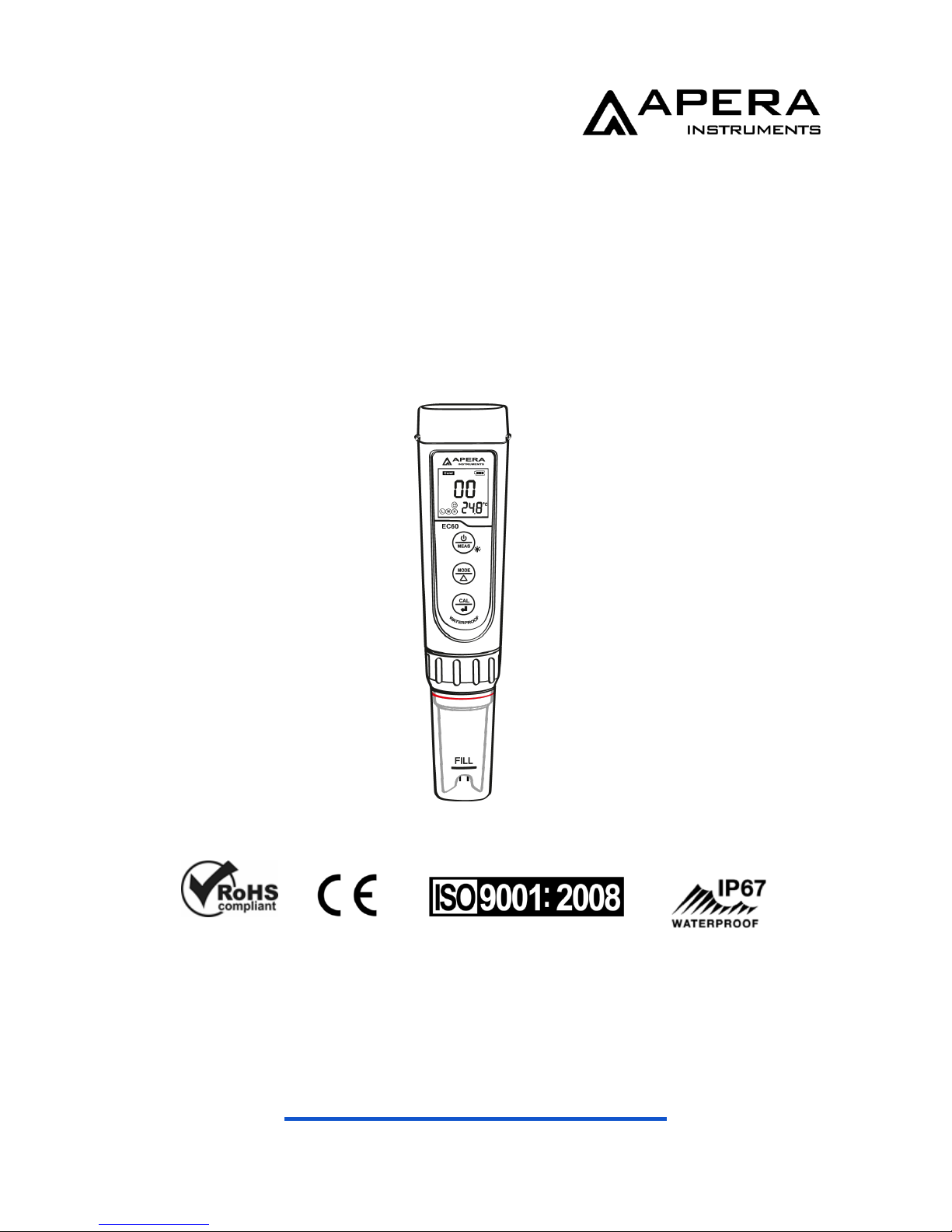
EC60 Premium Conductivity Tester
(EC/TDS/Salinity/Temp.)
Instruction Manual
APERA INSTRUMENTS, LLC
www.aperainst.com
Page 2
2
1 Battery Installation
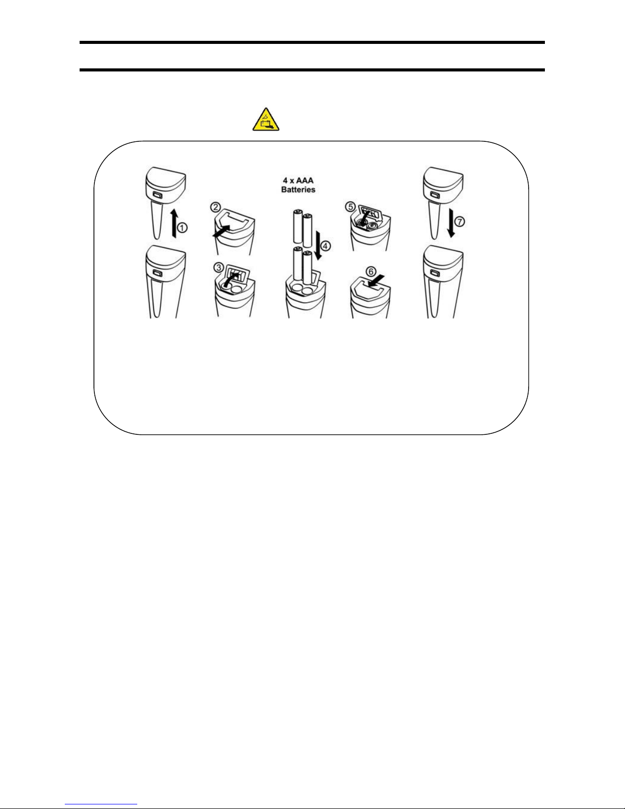
1.1 Please install batteries according to the following steps. *Please note direction of batteries: All
POSITIVE SIDES (“+”) FACING UP. (Wrong installation of batteries will cause damage to
the tester and potential hazards)
① Pull the battery cap up
② Slide the battery cap along to the direction of arrow
③ Open the battery cap
④ Insert the batteries (ALL POSITIVE SIDES FACING UP) (see graph)
⑤ Close the battery cap
⑥ Slide and lock the battery cap along to the direction of arrow
⑦ Fit the tester’s cap while making sure to push all the way down. The tester’s
waterproof design may be compromised if the cap is not fitted correctly.
Page 3
3
2 Keypad Functions
Short press — < 2 seconds
Long press — > 2 seconds
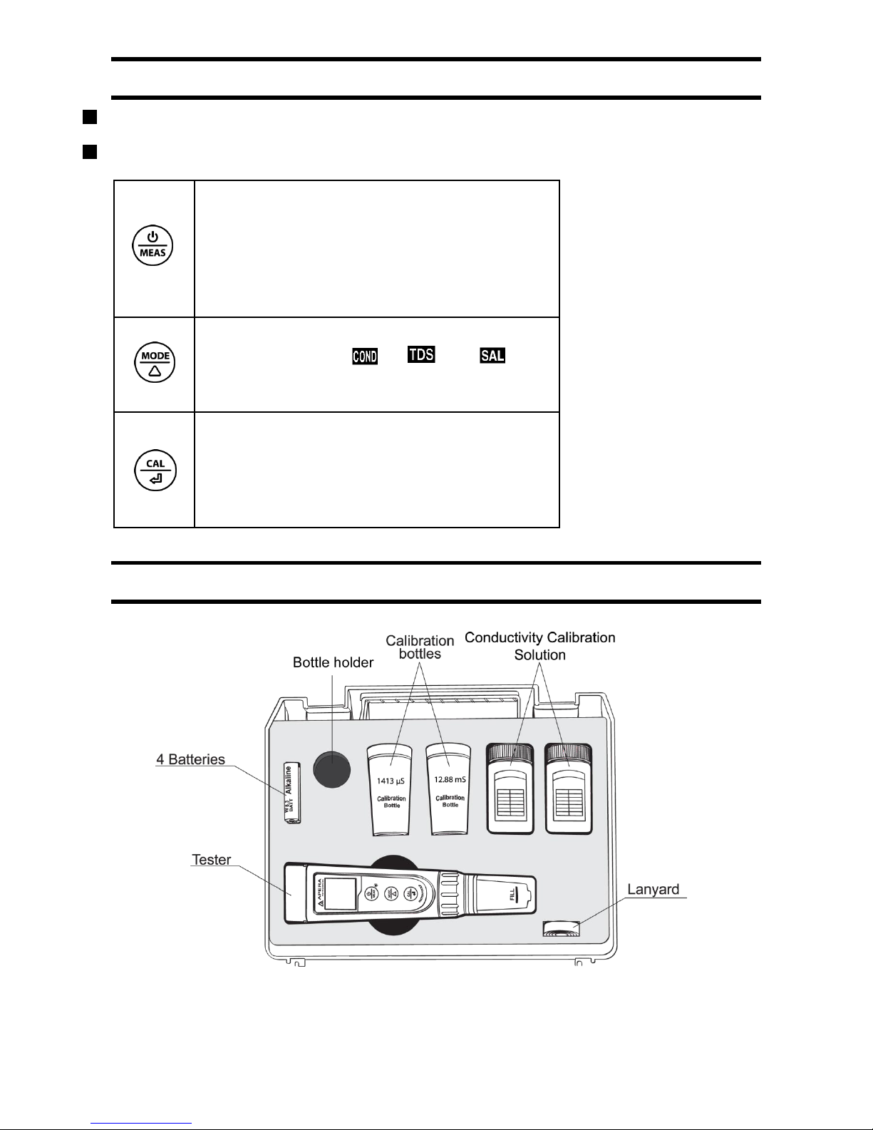
1. Short press to turn on the tester and long
press to turn off the tester.
2. When turned off, long press to enter
parameter setting.
3. In measurement mode, short press to turn
on backlight.
1. In measurement mode, short press to switch
parameter → →
2. In mode setting, short press to change
parameter (Unidirectional)
1. Long press to enter calibration mode.
2. In calibration mode, short press to confirm
calibration.
3. When measured value is locked, short press
to unlock.
3 Complete Kit
Graph - 2
Page 4
4
4 Conductivity Calibration
4.1 Press key to switch to conductivity measurement mode. Rinse the probe
in distilled water and dry it.
4.2 Pour certain amount (about half volume of the calibration bottle) of
1413μS/cm2 and 12.88 mS/cm2 conductivity calibration solution into accordant
calibration bottles.
4.3 Long press key to enter calibration mode, short press to exit.
4.4 Dip the probe in 1413 μS/cm2 conductivity calibration solution, stir gently and
allow it to stand still in the solution until a stable reading is reached. When stable
icon appears and stays on the LCD screen, short press key to complete one-point
calibration, the tester returns to measurement mode and indication icon will
appear at the bottom left of the LCD screen.
4.5 After calibration, dip the probe in 12.88 mS/cm2 conductivity calibration
solution. If the value is accurate, it is not necessary to conduct 2nd point
calibration. If it is inaccurate, follow the steps in 7.3 to 7.4 to complete the 2nd point of
calibration using 12.88 mS/cm2 buffer solution.
* 1000 µS/cm2 = 1 mS/cm2
* 1000ppm = 1ppt
Page 5
5
5 Conductivity Measurement
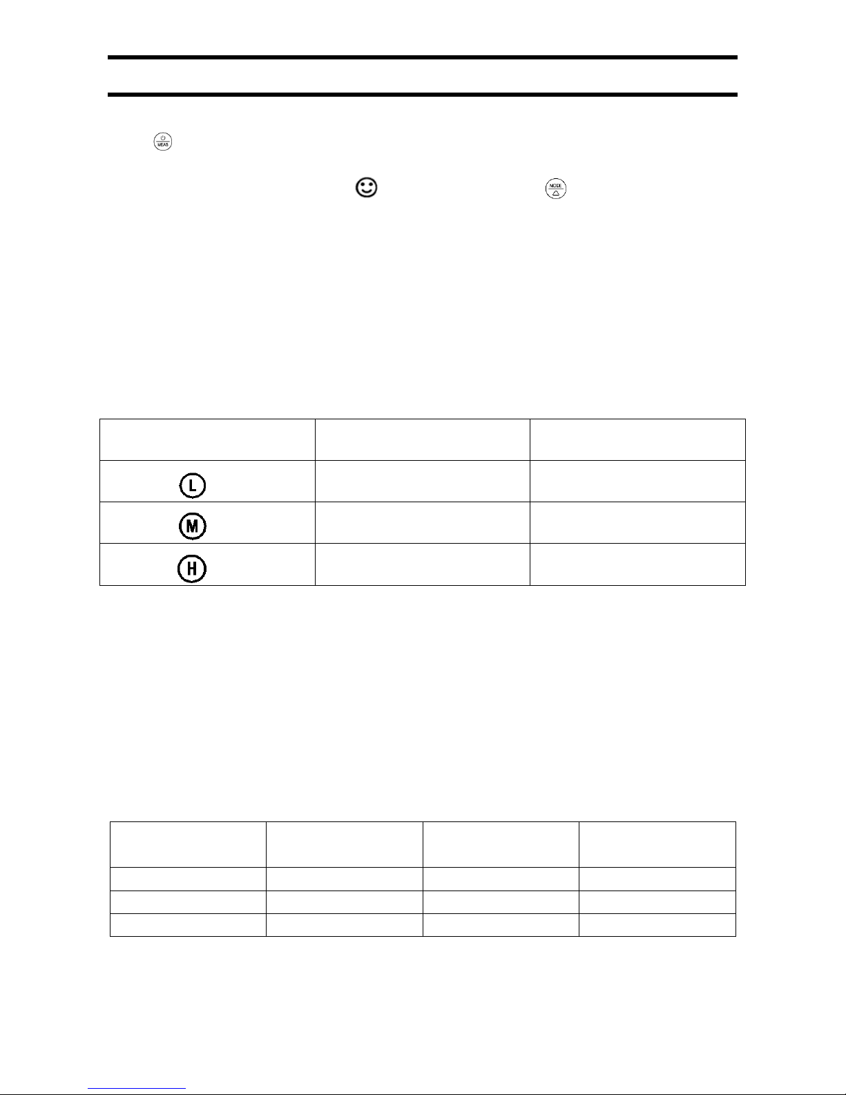
Press key to turn on the tester. Rinse the probe in distilled water and dry it.
Dip the probe in sample solution, stir gently, and allow it to stand still in the solution until a stable
reading is reached. Get readings after comes up and stays. Press to switch from Conductivity
to TDS, and Salinity
■ Notes
a) The TDS and Salinity measurements are converted from the conductivity
measurements via a certain conversion factor.
b) The tester can calibrate 84μS, 1413 μS and 12.88 mS conductivity calibration
solution. User can conduct 1 to 3 points calibration. Refer to the table below. Usually
calibrating the tester with 1413 μS conductivity buffer solution alone shall meet the
testing requirement.
Calibration Indication Icon
Calibration Standards
Measuring Range
84 μS/cm
0 - 200 μS/cm
1413 μS/cm
200 - 2000 μS/cm
12.88 mS/cm
2 - 20 mS/cm
5.1 The tester has been calibrated before leaving the factory. Generally, users can use the tester directly
or users can test conductivity buffer solutions first. If the error is large, then calibration is needed.
5.2 For conductivity calibration solutions, we recommend that users replace new solutions after 5 to 10
times of use to keep the standard solution’s accuracy. Do NOT pour the used calibration solutions back
into the solution bottles in case of contamination.
5.3 Temperature compensation factor: The default setting of the temp. compensation factor is 2.0%/℃.
User can adjust the factor based on test solution and experimental data in parameter setting P4.
Solution
Temperature
compensation factor
Solution
Temperature
compensation factor
NaCl
2.12%/˚C
10% Hydrochloric acid
1.32%/˚C
5% NaOH
1.72%/˚C
5% Sulfuric acid
0.96%/˚C
Dilute ammonia
1.88%/˚C
5.4 TDS and conductivity is linear related, and its conversion factor is 0.40-1.00. Adjust the
factor in parameter setting P5 based on the requirements in different industries. The factory
Page 6
6
default setting is 0.71. Salinity and conductivity is linear related, and its conversion factor is
0.5. The tester only needs to be calibrated in Conductivity mode, then after calibration of
conductivity, the meter can switch from conductivity to TDS or salinity.
5.5 Conversion Example: if conductivity measurement is 1000µS/cm2, then the default
TDS measurement will be 710 ppm (under the default 0.71 conversion factor), and the
salinity be 0.5 ppt.
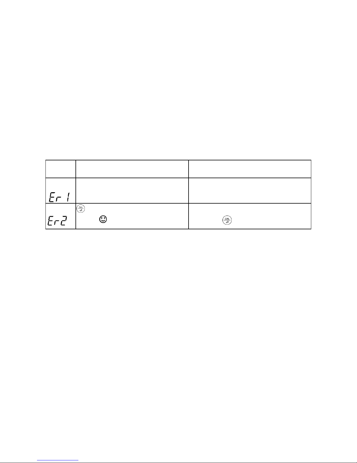
5.6 For the self-diagnosis information, please refer to the table below:
Symbol
Self-Diagnosis information
How to fix
Wrong conductivity buffer solution,
which exceeds the recognizable
1. Check if buffer solution is correct
2. Check if electrode is damaged.
Is pushed before measurement is
stable ( comes up and stays)
Wait for the smile icon to come up and
then press
Page 7
7
6 Parameter Setting
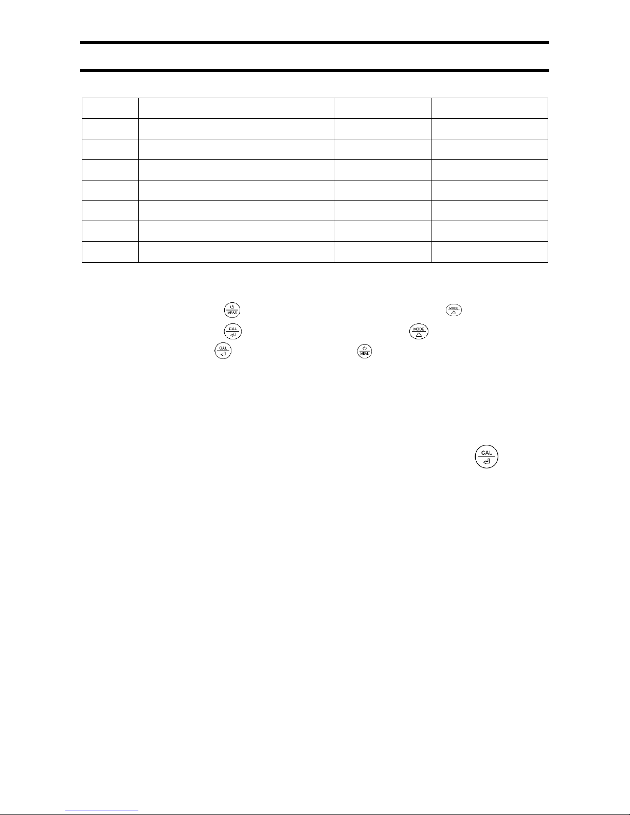
1) Parameter Setting Chart
Symbol
Content
Parameter
Factory Default
P1
Auto Hold
Off-On
Off
P2
Backlight
Off-1-On
1 (1 min auto-off)
P3
Temp. Compensation Coefficient
0.00 to 4.00%
2.00%
P4
TDS Coefficient
0.40 to 1.00
0.71
P5
Salinity Unit
ppt-mg/L
ppt
P6
Temperature Unit
˚C-˚F
˚C
P7
Restore to Factory Defualt
No-Yes
No
2) Parameter Setting
When turned off, long press to enter parameter setting →short press to switch
P1-P2… →P7. Short Press , parameter flashes→short press to choose
parameter, → short press to confirm →Long press to switch off.
3) Parameter setting notes
a) Auto Hold (P1):
Set “On” to turn on auto hold function. When reading has been stable for 10 seconds, the
meter will lock the reading automatically, and HOLD icon will appear. Press to unlock and
continue measuring.
b) Backlight (P2):
Off – turn off the backlight; On – turn backlight always on; 1 – backlight lasts 1 minute
c) Restore to factory default (P7):
Select “Yes” to restore the meter’s calibration and other parameters back to factory default
value. When meter’s calibration or measuring is performing abnormally, users can perform
this function. After restoring to factory default, conduct calibration and measurement again.
Page 8
8
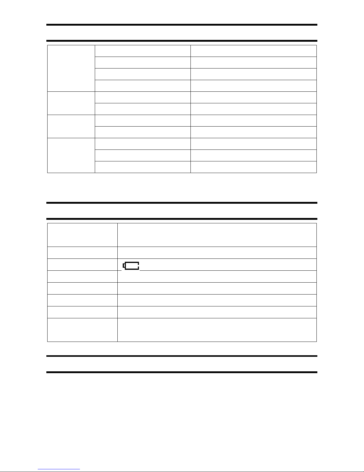
7 Technical Specifications
Conductivity
Range
0-200.0 µS, 0-2000 µS, 0-20.00 mS
Resolution
0.1/1 µS, 0.01 mS
Accuracy
±1% F.S
Calibration
1-3 points automatic calibration
TDS
Range
0-100,0 ppm, 0-1000 ppm, 0-10.00 ppt
Resolution
0.1/1 ppm, 0.01 ppt
Salinity
Range
0-10.00 ppt
Resolution
0.01 ppt
Temperature
Range
0-50˚C
Resolution
0.1˚C
Accuracy
±0.5˚C
8 Other Functions and Parameters:
Screen
STN 180˚ viewing angle.
Blue backlit: measuring mode; Green backlit: calibration mode
Readings’ Lock
HOLD
Low battery reminder
flashes to remind to replace batteries
Automatic power-off
Auto power-off if no operation in 8 minutes
Waterproof level
IP67, floats on water
Power supply
AAA batteries*4
Battery Life
1000 hours
Dimensions/Weight
Meter: 40*40*178mm/133g
Carrying case: 255*210*50mm/438g
9 Probe Replacement
Twist off the probe ring, unplug the probe, plug in the new replacement probe (pay attention
to the electrode’s position), and screw on the probe ring. The model for EC60 tester’s
replacement probe is EC60-E (AI209)
Page 9

9
10 Warranty
We warrant this instrument to be free from defects in material and workmanship and agree to repair
or replace free of charge, at option of APERA INSTRUMENTS, LLC, any malfunctioned or damaged
product attributable to responsibility of APERA INSTRUMENTS, LLC for a period of two years from
the delivery (a six-month limited warranty applies to probes). This warranty does not apply to defects
resulting from actions such as misuse (violation of the instructions in this manual or operations in the
manner not specified in this manual), improper maintenance, or unauthorized repairs. Warranty
period is the time limit to provide free service for the products purchased by customers, not the
service life of the tester or probe.
Page 10

10
APERA INSTRUMENTS, LLC
Address: 6656 Busch Blvd. Columbus, Ohio, 43229
Tel: 1-614-285-3080
Email: [email protected]
Website: www.aperainst.com
 Loading...