

Page 1
Page 1
APEN GROUP reserves the right to change products and documents as required.
code HG0109.12GB ed.C-1106 rev.12
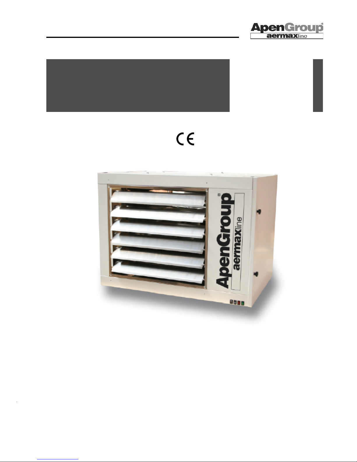
WARM AIR HEATER SERIES RAPID
RAPID
Warm Air Heater
ON-OFF
It is forbidden to totally or partially copy or reproduce this document for disclosure to third parties without written consent by Apen Group s.p.a.
User,
Installation,
and
Maintenance Manual
NEW SERIES
Page 2

Page 2
code HG0109.12GB ed.C-1106 rev.12
APEN GROUP reserves the right to change products and documents as required.
WARM AIR HEATER SERIES RAPID
Page 3

Page 3
APEN GROUP reserves the right to change products and documents as required.
code HG0109.12GB ed.C-1106 rev.12
WARM AIR HEATER SERIES RAPID
Statement of Compliance
-
APEN GROUP S.p.A.
20060 Pessano con Bornago (MI) - ITALY
Via Isonzo, 1
Ph. +39.02.9596931
Fax +39.02.95742758
Website: http://www.apengroup.com
With this document we declare that the unit:
Model: Suspended Heater RA- RAC
has been designed and manufactured in compliance with the prescriptions of the following EC Directives:
Machinery Directive 2006/42/CE
Gas Appliance Directive 90/396/CEE
Electromagnetic Compatibility Directive 2004/108/CE
Low Voltage Directive 2006/95/CE
If the unit is to be installed into an equipment (combined), the manufacturer disclaims any responsibility if this
equipment is not previously declared compliant with the requirements specied in IIB Enclosure of above said
Machinery Directive.
Pessano con Bornago
Apen Group S.p.A.
The General Manager
CODE
SERIAL NUMBER
Page 4

Page 4
code HG0109.12GB ed.C-1106 rev.12
APEN GROUP reserves the right to change products and documents as required.
WARM AIR HEATER SERIES RAPID
TABLE OF CONTENTS
SEZIONE 1. GENERAL WARNINGS................................................ 3
SECTION 2. SAFETY WARNINGS ................................................... 3
2.1 Fuel ........................................................................................ 3
2.2 Gas Leaks ............................................................................. 3
2.3 Power Supply .................................................................... 3
2.4 Use ........................................................................................ 4
2.5 Maintenance .......................................................................... 4
2.6 Transport and Handling ......................................................... 4
SECTION 3. TECHNICAL FEATURES ............................................. 5
3.1 Technical Data ....................................................................... 6
3.2 Noise ..................................................................................... 7
3.3 Dimensions ............................................................................ 8
SECTION 4. USER’S INSTRUCTIONS ............................................ 10
4.1 Description of the Heater ....................................................... 10
4.2 Heater Operation ................................................................... 10
4.3 Accessories ........................................................................... 11
SECTION 5. INSTRUCTIONS FOR THE INSTALLER ..................... 12
5.1 General Installation Rules ..................................................... 12
5.2 Installing the Heater ............................................................... 12
5.3 Chimney Piping ..................................................................... 15
5.4 Terminal Layout ..................................................................... 17
5.5 Electrical Wiring ..................................................................... 20
5.6 Gas Supply System ............................................................... 23
SECTION 6. INSTRUCTIONS FOR SERVICE STAFF ..................... 24
6.1 Country Table - Gas Category ............................................... 24
6.2 Gas Setting Data Table .......................................................... 25
6.3 First Startup ........................................................................... 26
6.4 Combustion Analysis ............................................................. 26
6.5 Converting the Unit to LPG .................................................... 26
6.6 Conversion to G25 - G25.1 - G2.350 gas .............................. 27
6.7 Maintenance .......................................................................... 27
6.8 Cleaning the Exchanger ........................................................ 28
6.9 Demolition .............................................................................. 28
SECTION 7. DIAGNOSTICS ............................................................. 29
SECTION 8. WIRE DIAGRAMS ........................................................ 30
SECTION 9. APPROVAL CERTIFICATE .......................................... 32
SECTION 10. SPARE PART LIST ...................................................... 34
Page 5

Page 5
APEN GROUP reserves the right to change products and documents as required.
code HG0109.12GB ed.C-1106 rev.12
WARM AIR HEATER SERIES RAPID
1. GENERAL WARNINGS
This manual is an essential component of the product and must
always accompany it.
If this equipment is sold or transferred to another owner, ensure
that the manual follows it, to enable the new installer/owner to
consult it.
The manufacturer disclaims any liability (under contract provisions or otherwise) for damage to persons, animals, or objects
resulting from wrong installation or misuse, and/or non compliance with the manufacturer’s instructions.
This unit is intended only and exclusively for the use for which
it has been built. Any different, wrong, or unreasonable use is
to be considered improper and therefore dangerous.
For installing, running and maintaining the unit, the user shall
strictly follow the instructions stated in this manual and shall
comply with existing national laws and regulations.
Any installation, maintenance or servicing operations shall be
performed only by authorized personnel, with technical skills
specic for the heating eld.
First start-up, conversion to another gas type and maintenance
must be exclusively carried out by qualied personnel appointed
by Apen Group authorized Service Centers, in compliance with
National laws and regulations.
Installation and maintenance operations shall comply with
the laws and regulations existing in the Country where the
appliance is installed.
APEN GROUP's business organization can count on a widespread network of approved Technical Support Centers. For
information, contact your local Representative or directly the
Manufacturer.
The unit is covered by a guarantee whose conditions and validity
are specied on the relevant certicate.
The manufacturer declares that the unit is workmanlike built in
compliance with UNI, UNI-CIG, and EC technical provisions,
and according to the relevant laws and to the Directive on Appliances burning gaseous fuels 90/396/EEC.
European Directives referenced:
- Gas Directive 2009/142/CE.
- Low Voltage Directive 2006/95/EEC.
- Machinery Directive 2006/42/CE
- Electromagnetic Compatibility Directive 2004/108/CE.
2. SAFETY WARNINGS
This section describes the safety rules for operators.
2.1 Fuel
Before starting the heater, check that:
Gas supply specications match those written on the rating plate;
- Combustion air inlet pipes (if installed) and ue discharge pipes
are exclusively those specied by the manufacturer
- The grid of combustion air intake system is free from debris,
leaves, etc.
- The gas seal of the feeding system has been tested and approved in compliance with the law.
- The heater's fuel is the one specied for the unit
- The unit is correctly sized to match required ow and includes
all safety and control devices required by the law
- Gas pipes and air distribution ducts for ducted heaters have
been properly cleaned
- Fuel rate of ow matches heater's rated input.
- Gas feeding pressure matches values on rating plate.
2.2 Gas Leaks
If you smell gas:
- Do not operate electrical switches, the telephone or any other
object or device that can cause sparks.
- Immediately open doors and windows to vent the room.
- Close gas valves.
- Call for qualied personnel.
2.3 Power Supply
The heater shall be correctly wired to an efcient grounding
system, complying with existing regulations (CEI 64-8).
WARNING:
- Check the grounding system or have it checked by qualied
personnel, if necessary.
- Make sure network wire gauge suits the unit rated input shown
on rating plate and in this Manual.
- Do not mistake neutral and phase wires.
The heater can be plugged into mains using a plug-socket only if
the latter prevents any mistake between phase and neutral wires.
- The system wire gauge in general, and cable section in particular, must suit the unit rated input shown on equipment rating
plate and in this Manual. Do not pull electrical wires and keep
them far from heat sources.
NB: A multipole switch with fuses and contact opening greater
than 3 mm should be installed before the supply cable, in a visible and accessible position and within 3 meters from the control
board. Any installation or maintenance operation concerning the
electrical system must be accomplished by qualied personnel.
2.4 Use
Page 6
Page 6
code HG0109.12GB ed.C-1106 rev.12
APEN GROUP reserves the right to change products and documents as required.
WARM AIR HEATER SERIES RAPID
HG0030 IM 001
Children and inexperienced people shall not be allowed to use
any electrical appliance.
The following precautions shall be adopted:
- Do not touch the unit with wet or damp parts of the body and/
or barefoot.
- Do not leave the unit exposed to adverse weather conditions
(rain, sunshine, etc.) unless the unit has been expressly designed to.
- Do not use gas pipes to ground electrical devices.
- Do not touch hot surfaces of the heater, such as ue pipes.
- Do not wet the unit either with water or other liquids.
- Do not put any objects on the unit.
- Do not touch moving parts of the heater while it is working.
2.5 Maintenance
Before running any servicing or cleaning, disconnect power
and gas supply by means of main ON/OFF switch and/or
appropriate detection devices.
In case of failure and/or insufcient running standards, switch
off the heater and do not attempt to repair it directly. Contact
the authorized Service Centre.
Use only original spare parts for repairs. Failure to follow above
instructions could compromise the unit safety and shall void
the warranty.
If the unit is not used for long periods, shut the gas off through
gas cocks and disconnect the unit from power supply.
If the unit is to be denitively decommissioned, in addition to
above suggestions, any potential source of hazard shall have
to be made inoffensive.
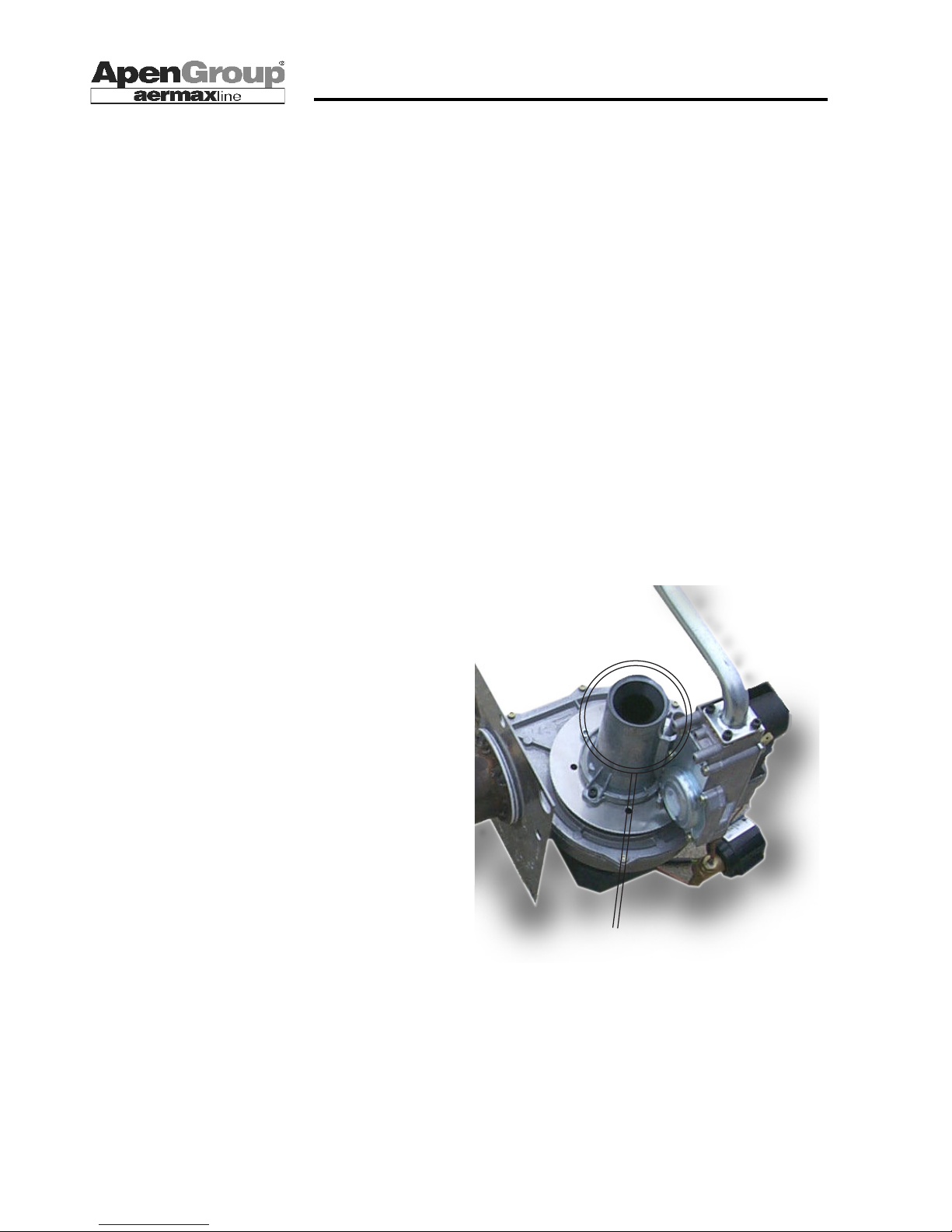
It is mandatory that the inlet of the Venturi tube on the burnerfan assembly is kept free from any debris or obstructions (see
gure in this page).
In case it is not, a backre from the pre-mix burner might occur.
2.6 Transport and handling
The heater is delivered fastened to a pallet and packed with
paperboard.
If required, the heater can be delivered packed on a pallet, in
a crate or in other forms.
Unload the heater from truck and move it to the installation place
using a convenient system, suited to the weight of the load.
If the unit is stored at the customer’s premises, make sure a
suitable place is chosen, sheltered from rain and excessive
humidity.
Any lifting and transport operations must be accomplished by
skilled personnel, adequately trained on working procedures
and safety rules.
Once the unit is placed in the right spot, you can start unpacking it
Unpack the heater using suitable tools and protections, where
necessary.
Materials resulting from unpacking shall be disposed of according to relevant regulations.
While unpacking the unit, check its integrity and its compliance
to the order.
Should damages or missing pieces result, immediately inform
the supplier.
The manufacturer is not liable for any damages occurred during
transport, handling, or unpacking.
KEEP FREE AND UNCLOGGED!
Page 7
Page 7
APEN GROUP reserves the right to change products and documents as required.
code HG0109.12GB ed.C-1106 rev.12
WARM AIR HEATER SERIES RAPID
HG0109.09_D_001 IT_ed.0902
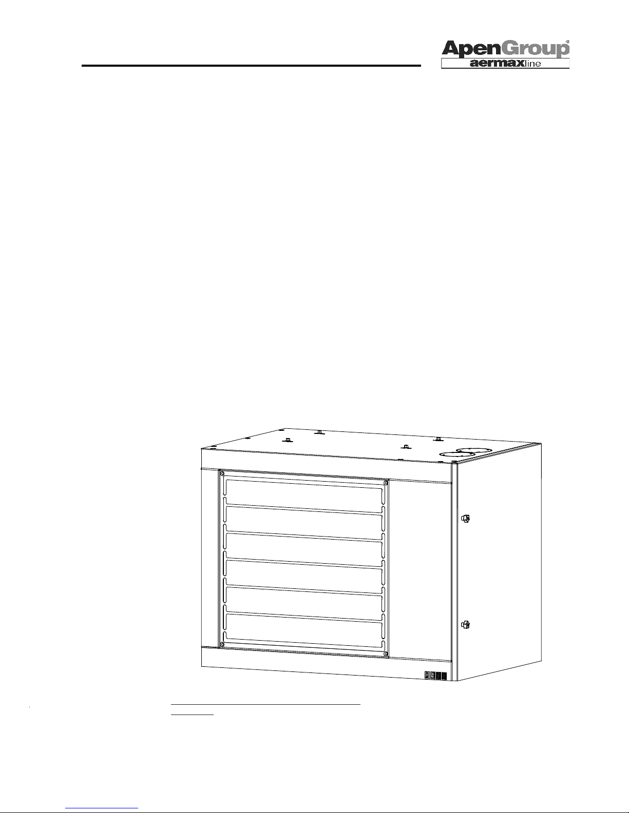
Attencion:before commissioning the heater, open louvers of
at least 45°
3. TECHNICAL FEATURES
Modulating air heaters series RAPID have been designed to
serve as heating units in industrial and commercial environments.
The control devices installed inside the control board allow to
fully manage the heater.
Pre-mix technology allows obtaining high efciency levels and
keep NOx emissions low.
The heater works as a standalone unit. In order to start it up,
just connect it to power and gas supply.
The unit's heat output ranges from 15.3 to 53.4 kW.
The heat exchanger complies with production requirements for
gas equipment set by EN1020 regulations.
The combustion chamber is entirely built in AISI 430 stainless
steel while tube bundles are made of AISI 441, in order to assure
high resistance to corrosion of wet ue.
The leading-edge design and the wide surface of the furnace
and tube bundle guarantee optimum efciency and durability.
The burner is entirely built with stainless steel, and it takes
advantage of special mechanical solutions to guarantee optimal
reliability and performance rates, as well as high thermal and
mechanical resistance.
The security level of the equipment is IP X0D [IP20] according
to EN 60529.
RAPID heaters work in ON/OFF mode, i.e. thermal output, and
therefore thermal input and fuel consumption, remain steady
and are based on heat request.
When the heater is turned on, the burner starts working at
maximum capacity.
Low Pollution
Pre-mix burners equipped with an air/gas valve allow "clean"
combustion with very low polluting emissions.
Nox Class 4 - EN1020
Page 8
Page 8
code HG0109.12GB ed.C-1106 rev.12
APEN GROUP reserves the right to change products and documents as required.
WARM AIR HEATER SERIES RAPID
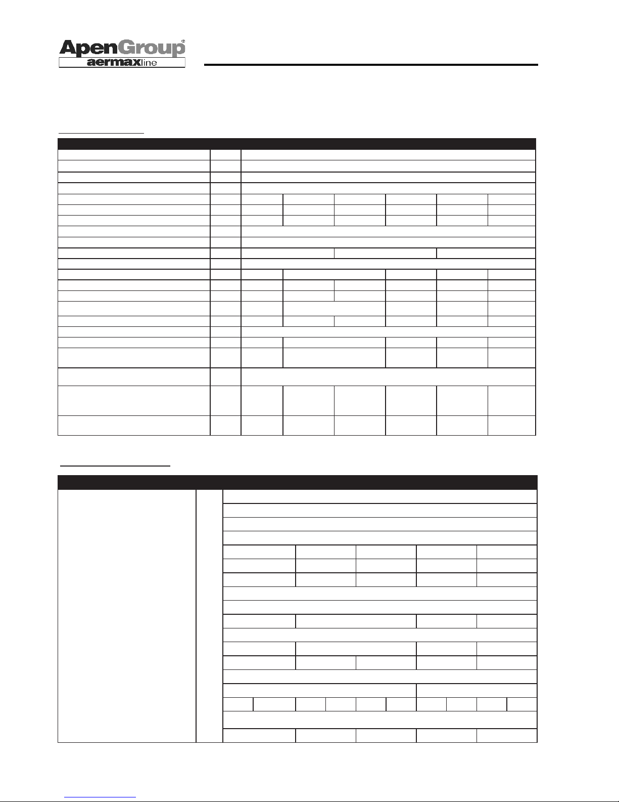
3.1 Technical data
Models with axial fan
Models with centrifugal fan
RA015 RA024 RA032 RA035 RA043 RA054
TECHNICAL DATA UOM max
Type of appliance
C13 - C33 - C53 - C63 - B23
EC Approval P.I.N. 0694BN4077
Protection degree IP20
Rated thermal output kW 16,5 26,5 34,8 38,7 47,5 58,0
Rated thermal input kW 15,3 24,3 31,7 34,9 43,6 53,4
Efciency % 92,6% 91,8% 91,2% 90,2% 91,8% 92,1%
Ø of gas tting UNI ISO 7/1 - 3/4" M
Ø of inlet air/ue exhaust pipe mm 80/80
Press. available on ue exhaust Pa 50 90 110
Supply Voltage V 230V/50Hz
Input power W 220 260 330 520 620
Air Flow Rate at T=15°C m3/h 1.600 3.050 3.050 3.800 5.000 6.250
Temp. increase Air °C 27,4 22,9 29,8 26,3 25,0 24,5
N° and Ø of fan 1 x 350 1 x 400 1 x 420 2 x 400 2 x 420
Fan speed g/1' 1.050 1.270 1.270 1.350 1.270 1.350
NOISE LEVEL UOM max
Noise level (Lw) dB(A) 66,4 70,9 74,1 73,9 77,1
Noise level in free eld 6m (Lp) dB(A) 39,9 44,4 47,5 47,4 50,5
Minimum operating temperature °C -15,0 / +60,0
Heater net weight (unpacked) Kg 59 65 69 75 92 97
Heater gross weight (packed) Kg 70 80 84 90 112 117
RAC024 RAC032 RAC035 RAC043 RAC054
TECHNICAL DATA UOM max
Type of appliance C13 - C33 - C53 - C63 - B23
EC Approval P.I.N. 0694BM3433
Nox Class val. 5
Rated thermal output kW 26,5 34,8 38,7 47,5 58,0
Rated thermal input kW 24,3 31,7 34,9 43,6 53,4
Efciency % 91,8% 91,2% 90,2% 91,8% 92,1%
Ø of gas tting
UNI ISO 7/1 - 3/4" M
Ø of inlet air/ue exhaust pipe mm 80/80
Press. available on ue exhaust Pa 50 90 110 120
Supply Voltage V 230V/50Hz
Input power W 245 500 490 1000
Air Flow Rate m3/h 2.250 2.800 2.800 4.500 5.600
AVAILABLE STATIC PRESSURE Pa 120
Fan number 1 2
Temp. increase Air °C 31,0 0,0 32,5 0,0 35,7 0,0 27,8 0,0 27,3 0,0
Min/max operating temperature °C -15 / +60
Weight kg 84 96 101 134 140
Page 9
Page 9
APEN GROUP reserves the right to change products and documents as required.
code HG0109.12GB ed.C-1106 rev.12
WARM AIR HEATER SERIES RAPID
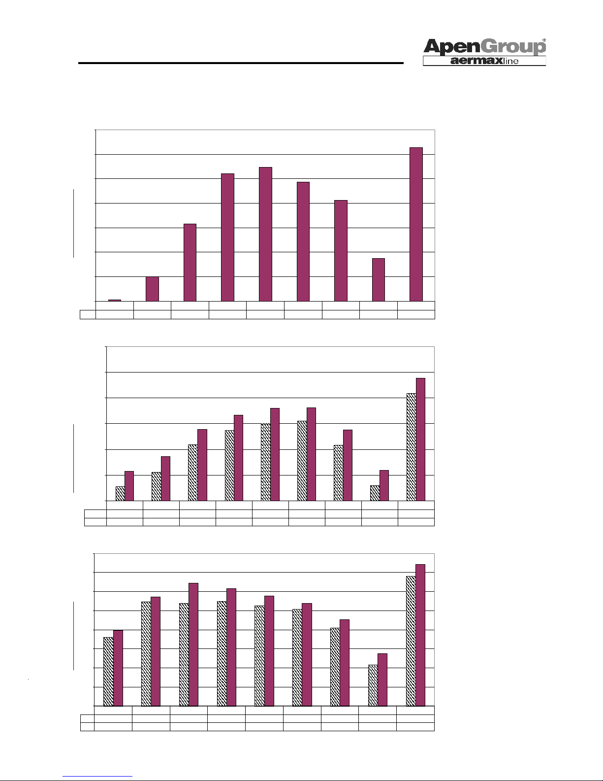
3.2 Sound Power - Noisiness
Noise level
It is known that the sound
power level of a source
(energy radiated/time unit)
is a characteristic measure
of the source itself and does
not depend on the surrounding environment. This level
allows comparisons between
different appliances.
As to measuring the sound
power level of a machine (not
in a workshop),
please refer to the following
document:
- ISO 3744 (1994)
The method proposed by the
document applies to any kind
of noise and device, provided
it is installed on a solid and
reecting surface (the wall
behind, in case of a blower).
ISO 3744 regulations require that test environment
is deprived of reflecting
surfaces, except for the one
the device is placed upon.
This simulates as much as
possible free eld conditions.
(These conditions can be
found outdoor, away from
walls or obstacles, or in a
semi-anechoic chamber).
The accuracy of the measurement depends on the engineering method used (2nd
degree. The reproducibility of
the results (obtained in different test environments) can
be expressed with a standard
deviation below 1,5 dB.
APEN GROUP has chosen
to use one-speed fans, in
order to increase the air ow
rate and the output efciency
of the equipment, thereby
decreasing air layering in
the room. This also reduces
the time required to heat the
environment.
RA015
35
40
45
50
55
60
65
70
1 speed
35,3
40,0
50,8
61,0
62,3
59,3
55,6
43,7
66,4
63Hz
125Hz
250Hz
500Hz
1000Hz
2000Hz
4000Hz
8000Hz
Totale
Noise level dB(A)
RA024 - RA032 - RA043
50
55
60
65
70
75
80
RA024, 032
52,8
55,6
60,9
63,7
65,0
65,5
60,8
53,0
70,9
RA043
55,8
58,6
63,9
66,7
68,0
68,1
63,8
56,0
73,9
63Hz
125Hz
250Hz
500Hz
1000Hz
2000Hz
4000Hz
8000Hz
Totale
Noise level dB(A)Noise level dB(A)
RA035 - RA054
40
45
50
55
60
65
70
75
80
RA035
58,1
67,3
67,0
67,5
66,3
65,3
60,4
50,8
74,1
RA054
59,8
68,7
72,3
70,8
68,9
66,9
62,6
53,7
77,1
63Hz
125Hz
250Hz
500Hz
1000Hz
2000Hz
4000Hz
8000Hz
tot.
Page 10
Page 10
code HG0109.12GB ed.C-1106 rev.12
APEN GROUP reserves the right to change products and documents as required.
WARM AIR HEATER SERIES RAPID
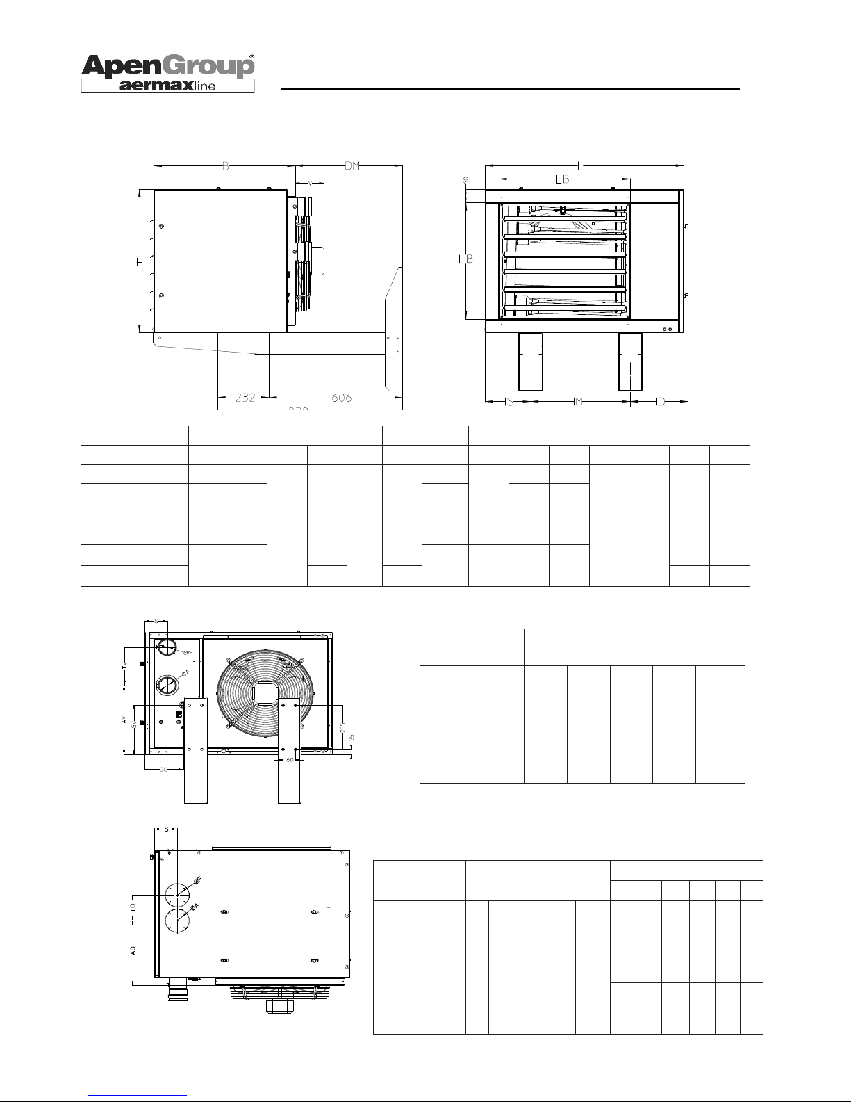
3.3 Dimensions
HG0109.12_C2_002
HG0109.12_C4_004_IT
HG0107.08_C2_003 IT_ed.0609
HG0109.12_ET_003
HG0109.12_ET_004
A Combustion Air Inlet Pipe
F Flue Pipe
HG0109.12_ET_002
HEATER SIZE LOUVER BRACKETS GAS SUPPLY
MODEL L B H V HB LB IM IS ID DM GAS GO GV
RA015
720
640
650
140
530
415
450
116 174
475 3/4"
186 263
RA024
900 595 206 264
RA032
RA035
RA043
1240 935 780 228 252
RA054
740 620 183 352
HEATER STANDARD HORIZONTAL OUTLETS
MODEL A F AV TV S
RA015
80 80
367
204 105
RA024
RA032
RA035
RA043
RA054
457
HEATER OPT. VERT. OUTLETS TOP HOLES
MODEL A F AO TO S D1 D2 D3 D4 D5 D6
RA015
80 80
305
120
105
244 450 206 290 232 118
RA024
RA032
RA035
RA043
230 780 228 290 232 122
RA054
310 100
Page 11
Page 11
APEN GROUP reserves the right to change products and documents as required.
code HG0109.12GB ed.C-1106 rev.12
WARM AIR HEATER SERIES RAPID
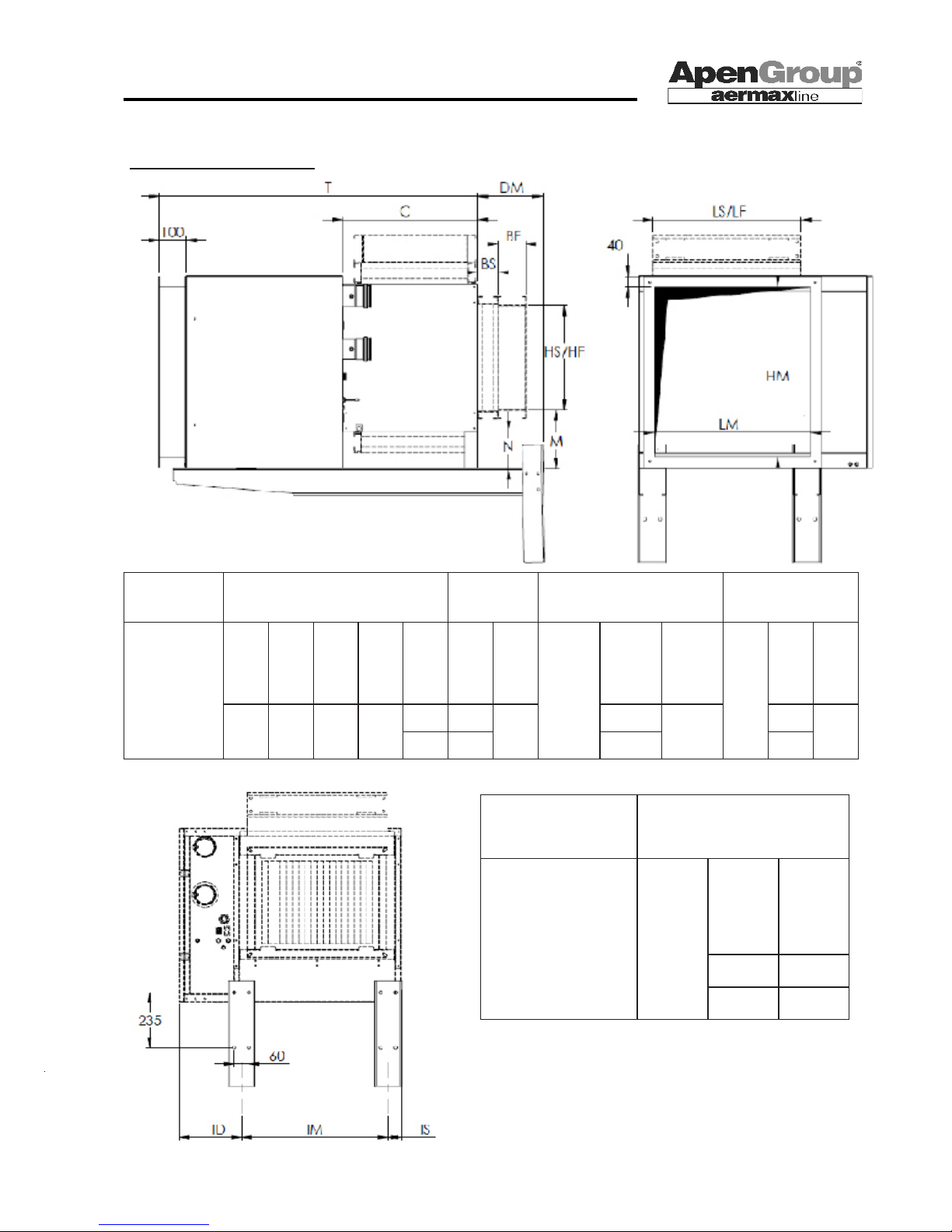
Dimensions with eased frame
Shutters, brackets and lters for heaters with eased frame
are considered accessories and are not supplied with the
equipment.
HEATER DIMENSIONS DELIVERY SHUTTERS/INTAKE FILTERS
MODEL
T DM C N M HM LM BS HS
LS BF HF LF
024
1225 260 520 102 155 500 600
80
410 510
105
400 500
032
035
043
1315 200 580 90
125 550
950
460
710
450
700
054
145 650 510 500
HEATER BRACKETS
MODEL IS IM ID
024
52
595 252032
035
043 910 277
054 960 227
Page 12
Page 12
code HG0109.12GB ed.C-1106 rev.12
APEN GROUP reserves the right to change products and documents as required.
WARM AIR HEATER SERIES RAPID
4. USER'S INSTRUCTIONS
Read General and Safety Warnings on page 3.
The user shall only use the room thermostat controls
and possibly the commands installed on the unit.
4.1 Description of the heater
Suspended warm air heaters of RAPID series heat air by direct
exchange, with a combustion circuit sealed from the room they
are installed into.
Their patented heat exchanger, furnace and premix burner are
entirely made of stainless steel.
Therefore, you can install our heaters in any of the industrial or
residential environments where the existing regulations allow
air recirculation in the room.
The heater works in fully automated mode. It includes a selfchecking electronic device that regulates all burner controls and
commands, thereby ensuring top reliability and safety.
4.2 Heater Operation
In order to ensure proper operation, the heater shall be connected
to a room thermostat and/or a timer that automatically starts
the working cycle.
Apen Group can provide suitable accessories for unit control.
WINTER: heating mode
To operate the heater, please do the following:
- Make sure gas supply cock is open
- Check the green LED is on (it indicates the unit is powered.)
- Turn the I/0/II switch on “I = Winter”;
- Close room thermostat contact and make sure that the timer,
if installed, is OFF.
These are the prerequisites to launch burner start-up cycle.
The ame control device starts up the burner that launches the
furnace pre-washing phase. The ame is lit about 30 seconds
afterwards.
A detection electrode checks the burner has actually red. In
case it has not, the start up sequence is repeated 4 times before
locking the unit.
30 seconds after the burner is red, the fan automatically starts
to blow air in the room. In winter mode, the burner and the fan
work continuously without stopping.
When the set temperature is reached, the room thermostat turns
the burner off. The fan keeps working for 120 seconds to cool
the exchanger down while the fan in the burner post-washes
the furnace for 60 seconds.
The burner restarts when a heat request is issued by room
thermostat.
The heater shall not be turned off by disconnecting it from the
mains while it is running. In such case, the exchanger would
not be cooled down, its durability would be jeopardized and
the guarantee would be void.
Locking the heater
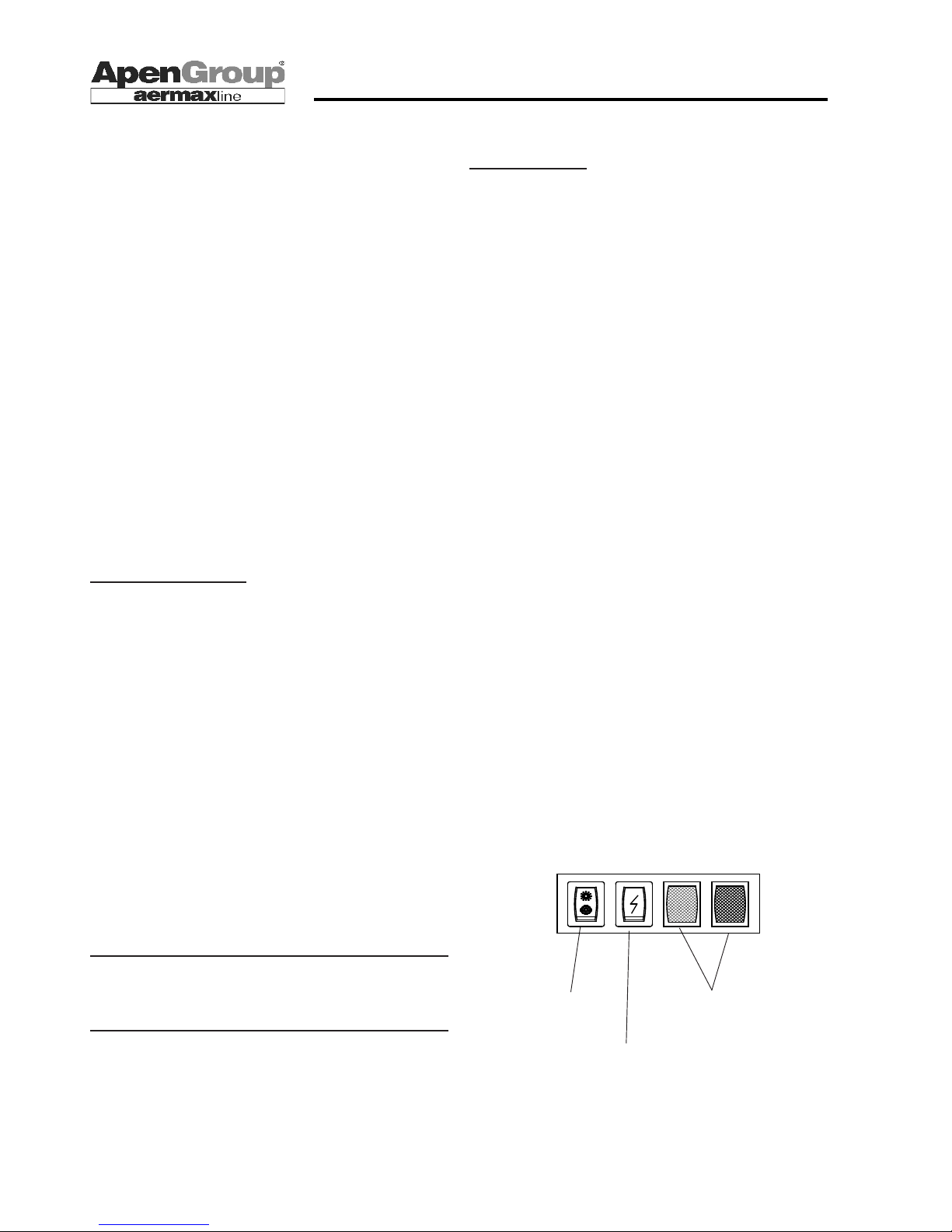
On the front of the heater a red LED is installed to show if the
equipment is locked. This LED can light up for two reasons:
- The burner locks up (no ame)
- Safety controls lock up
In case of a lock, you can reset the unit manually by pressing
the button on the front of the heater for longer than 1 second.
This button can also be remotely controlled (see wiring diagrams
in the section reserved for the installer).
If the units locks up again after 35/40 seconds
If after two or three reset attempts the lock is not resolved, do
not insist and contact your Support Center for a repair call.
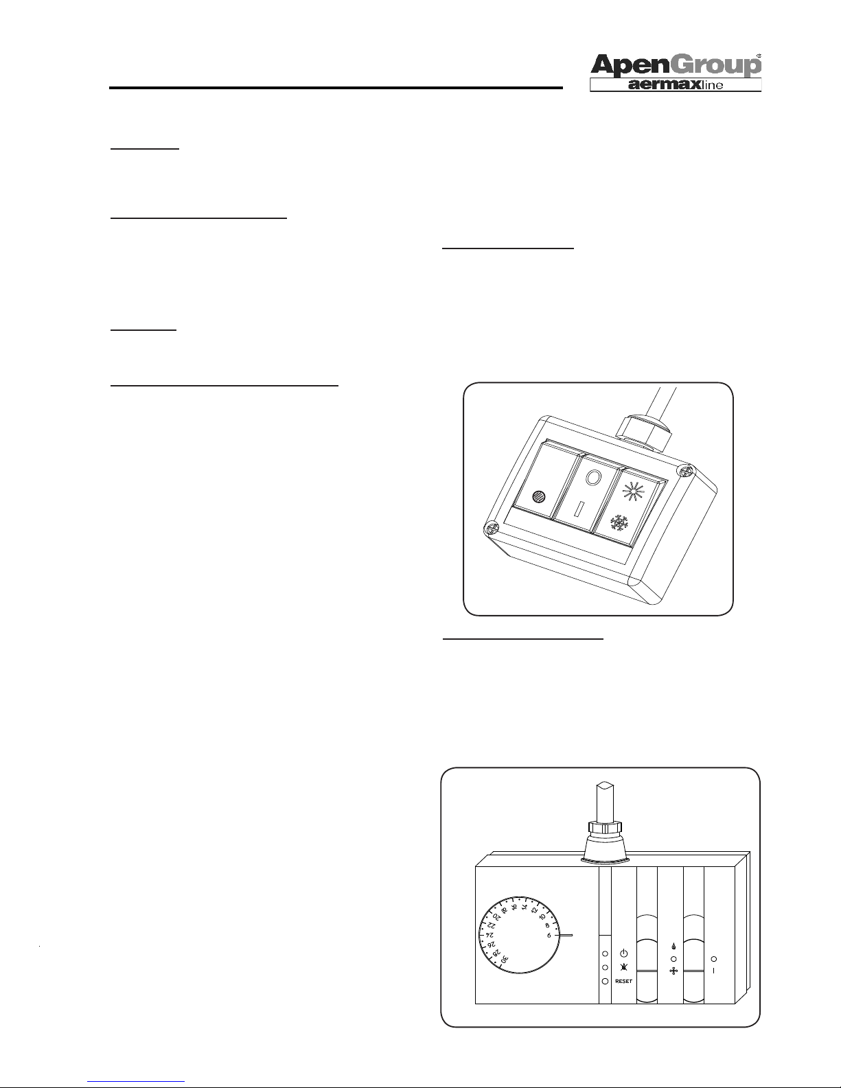
Summer /0 /Winter
switch
Line and lock
LEDs
Reset button
Page 13
Page 13
APEN GROUP reserves the right to change products and documents as required.
code HG0109.12GB ed.C-1106 rev.12
WARM AIR HEATER SERIES RAPID
Burner lock:
If the ame control device detects an ignition failure of the burner,
the start-up cycle is automatically repeated up to 4 times. If the
lock continues, the red LED on the front of the heater turns on.
Safety thermostat locked (STB):
A safety thermostat (STB) for each cooling fan is installed on
the heater.
The STB thermostat is a safety device that triggers if a fault
occurs. Thermostat is automatically reset by AGP card. When
the STB thermostat triggers, the red LED on the front of the
heater is lit (the same as for burner lock).
Diagnostics
To nd out the reason of the lock, refer to "Diagnostics" section
in paragraph 7.
SUMMER : operation in ventilation mode
The heater can be used also in summer to have air ow in
the room.
To enable summer ventilation, turn I/O/II switch on “II = Summer”.
REMARK: If you want to remotely control the Summer/Winter mode, please leave the switch on the heater
turned on Winter [ pos. I ].
If you power off the unit before cooling cycle is completed
and then power it on again, fans star immediately.
HG0100 C2 012
4.3 Accessories
To ease the use of the heater, APEN can supply two accessories
that allow to remotely control heater's commands.
Available commands are described below. Please refer to
the "instructions to the installer" section for electrical wiring
instructions.
Remote Control G12800
G12800 remote control includes ON/OFF [0/I] command, summer/winter switch, and reset button.
You do not power off the unit by turning the 0/I switch off. You
simply have the ame extinguished while the exchanger is
properly cooled down.
However it is necessary to reset the safety thermostat (STB) is
on the remote control.
Remote control code G00094
This command enables to:
- Set room temperature
- Switch Summer/Winter operation
- Turn off the heater without powering it down
- Display burner lock
- Reset the burner
With this command too, the only way to reset the safety thermostat
(STB) is on the remote control.
HG0107.08_C2_005 IT
Page 14
Page 14
code HG0109.12GB ed.C-1106 rev.12
APEN GROUP reserves the right to change products and documents as required.
WARM AIR HEATER SERIES RAPID
HG0103 C2 009
HG0103 C2 008
HG0103.C2 007
5. INSTRUCTIONS TO THE INSTALLER
Instructions for installing and setting the heater are intended
for authorized personnel only.
Read safety rules rst.
5.1 General Installation Rules
If possible, the heater should be installed directly in the
room to be heated.
For indoor installation, different laws and regulations apply
according to the fuel that is used and the Country where
the appliance is installed.
The installer shall strictly follow the laws and regulations
existing in the Country where the appliance is installed.
Venting Openings
The room where a gas-red heater is installed must comply with
relevant regulations as to the number and dimensions of venting
openings, in order to guarantee optimum combustion and safety.
These openings shall comply with existing relevant national and
international regulations.
- a lo del softto per i gas con densità inferiore a 0.8;
- a lo del pavimento per gas con densità superiore o uguale a 0,8.
Le aperture devono essere eseguite su pareti attestate su spazi
a cielo libero. Le sezioni vanno dimensionate in Feature della
Heat Ouput installata.
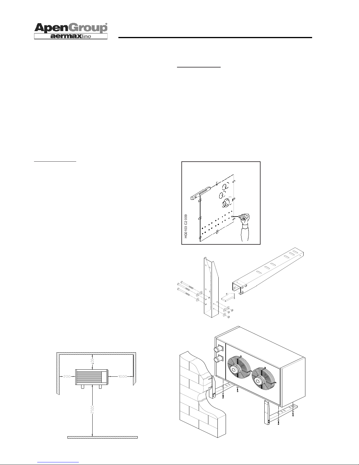
5.2 Installing the Heater
The diagram on the right shows installation height and clearance
of the heater from walls and oor. Minimum clearance (in mm)
indicates the space required to assure proper maintenance.
Height (2,500 mm) is the minimum value required by the law
for wall-mounted heaters. In front of the heater, a clearance of
at least 3 meters shall be provided. Behind the unit the space
must be equal or greater than "DM" value shown in "Dimensions"
paragraph on page 7 of the Manual. Two types of brackets are
available on demand: xed and revolving. With RAC models,
only xed brackets can be used.
Codes for available brackets are the following:
G15200-0N00 Fixed brackets for RA015/054
G15650-0N00 Revolving brackets for RA015/035
G15610-0N00 Revolving brackets for RA043/054
G13600 Kit for xed bracket RAC024/054
FIXED BRACKETS
Installation procedure:
- Place drilling template on the wall and mark the holes to drill.
- Assemble the brackets as shown in gure below, using supplied parts.
- Use screw anchors with outer M10 screw.
REMARK: Make sure screw and anchor size and type are
suitable for holding the heater on the specic wall type.
- When assembling brackets, insert an elastic locking washer
between bracket and locknut.
- Place heater on brackets, taking care to centre it. Make also
sure panel boring coincide with bracket holes. Bracket ends
must not lean out from the heater edge.
- Lock the heater using M8 screws supplied and inserting an
elastic locking washer between the screw and the bracket.
MINIMUM CLEARANCE
HG0107.10 C2 005
Page 15
Page 15
APEN GROUP reserves the right to change products and documents as required.
code HG0109.12GB ed.C-1106 rev.12
WARM AIR HEATER SERIES RAPID
HG0107.08_C2_006 IT_ed.0609
HG0107.08_C2_007 IT_ed.0609
HG0107.08_C2_008 IT_ed.0609
HG0100C2 011
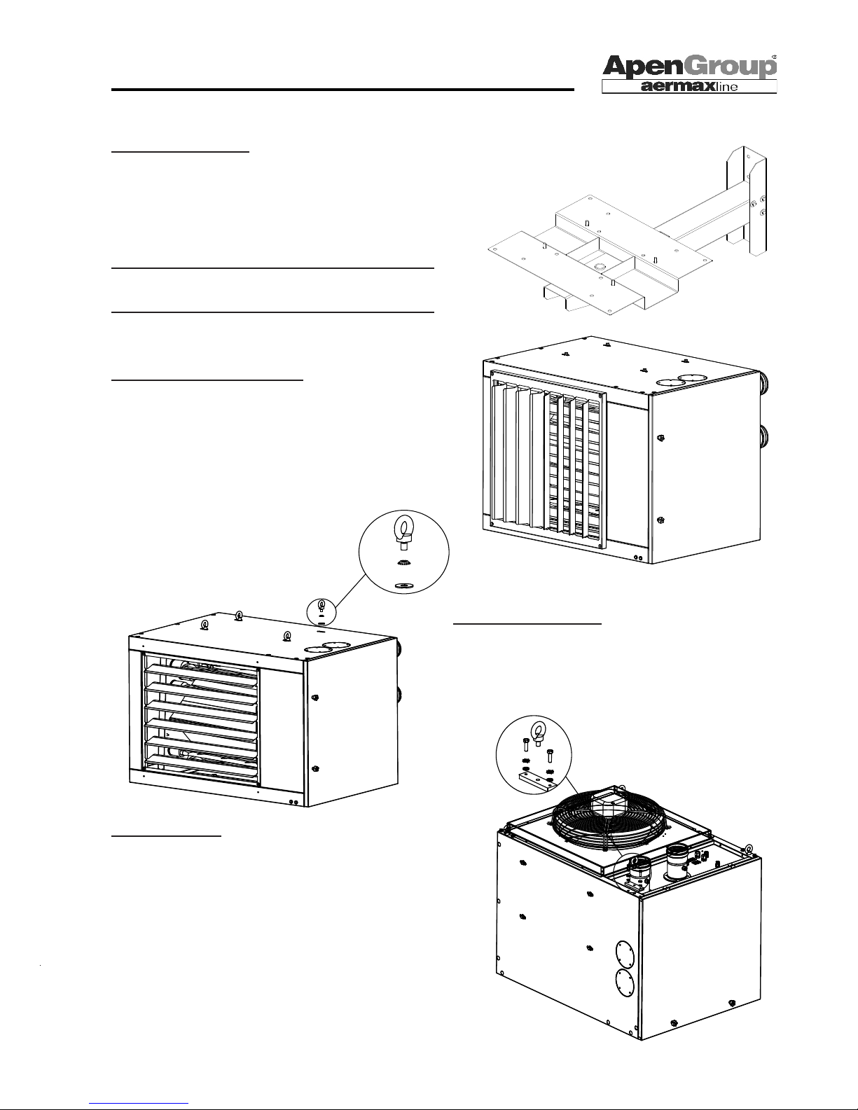
REVOLVING BRACKETS
Assembly instructions for revolving brackets are enclosed in
the package.
Revolving brackets are recommended in the following cases:
a) Installation in a corner
b) Installation on a pillar
c) Perpendicular installation to the wall the heater is hanged on
HEATER WITH BIFILAR LOUVERS
The available accessory kits have the following codes:
G15101 Vertical louvers for RA015
G15102 Vertical louvers for RA054, RA032, RA035
G15103 Vertical louvers for RA043
G15104 Vertical louvers for RA054
Install the louvers using pre-drilled holes in heater upper and
lower panel.
WALL-MOUNTED HEATER
To install the heater using eye-bolts, a kit is available G14444.08.
Simply replace upper screws with eye-bolts.
VERTICAL HEATER
Rapid heaters can be installed with downwards air blow (vertical
air ow).
This type of heater is not standard as it includes G14437.08 kit
and additional thermostats for air fan control. These devices
are already assembled in the delivered heater.
If the G14437.08 kit is to be installed on the outside, have the
installer read the technical sheet included in the kit.
REMARK: Kit G14437.08 does not include suspension eyebolts.
Ask for G14444.08 kit, if required (see above).
REMARK: Additional thermostats checking fan operation
are installed and connected in series to STB1 and STB2
thermostats (see wiring diagram).
Note: Make sure screw and anchor size and type suit
wall type and are adequate to hold the heater.
Page 16
Page 16
code HG0109.12GB ed.C-1106 rev.12
APEN GROUP reserves the right to change products and documents as required.
WARM AIR HEATER SERIES RAPID
FilterFireproof
Power
connection
cable
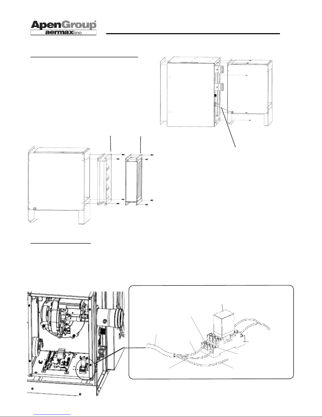
ASSEMBLING EASED FRAME AND ACCESSORIES
In order to assemble the heater to eased frame, fan compartment
shall be mounted on the heater using supplied screws (see gure).
To fasten shutters or lters to eased frame, tighten M8 screws
supplied in the kit to the nuts on eased frame. To fasten lters
to the shutter, both nuts and M8 screws are needed.
WIRING THE EASED FRAME
Inside burner compartment, a relay is already wired to wiring
card. The wire from eased frame shall be wired to this relay
as described in the gure. No problem if brown and grey wires
are reversed.
Contact NO
14-5
Contact
44 -8
Gray wire
(Neutral)
Brown wire
(Phase)
Yellow/green wire
(Ground)
Wire from
eased frame
Connection from the card
to A1- A2 terminals of the
relay
(already wired)
code X01061
code X01076
(230V)
Page 17
Page 17
APEN GROUP reserves the right to change products and documents as required.
code HG0109.12GB ed.C-1106 rev.12
WARM AIR HEATER SERIES RAPID
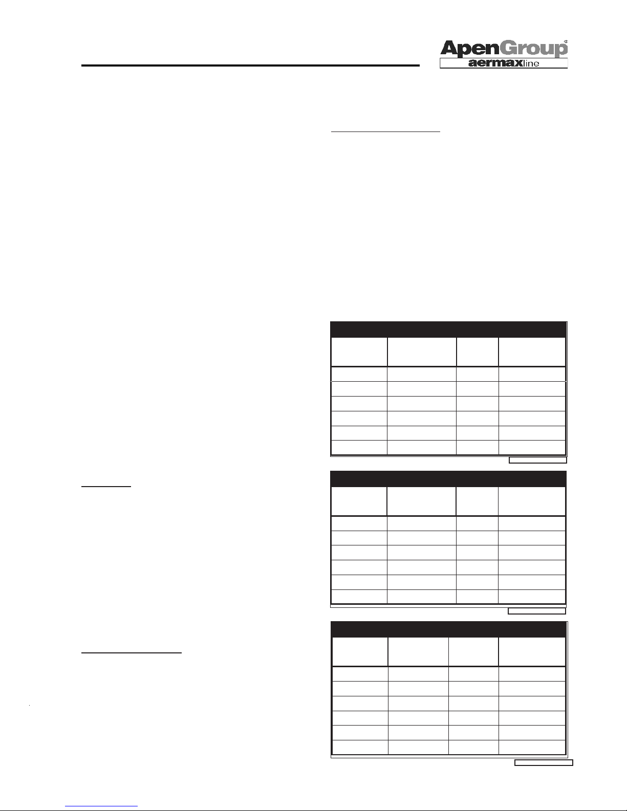
CO and NOx values are correct if O2=0%.
HG0109_12_ET_007
VALUES MEASURED WITH G20 [Natural gas]
Model CO NOx NOx Class
ppm ppm EN1020
RA015 1 42 4
RA024 1 40 4
RA032 1 44 4
RA035 1 41 4
RA043 1 50 4
RA054 1 44 4
5.3 Chimney Piping
RAPID heaters have sealed combustion circuits, and the fan is
installed before the exchanger.
The ue system can have different layouts: type C (combustion
air taken in from outdoor) or type B (combustion air coming
from indoor).
RAPID heaters are certied for the following ue types: C13-
C33-C53-C63-B23.
Use approved pipes and terminals for ue systems.
Intake and ue piping shall avoid the entry of objects having
one dimension larger than or equal to 12 mm.
APEN GROUP certies its own air intake and ue terminals,
which shall be installed with RAPID heaters.
The standard version of RAPID heaters is equipped with hori-
zontal ttings for connecting the heater to the chimney and to
air intake system. These ttings are on the back of the heater
but they can be moved to the top during installation in order to
ease exhaust from the roof.
Flue piping for non condensing RAPID heaters must be built
using the following materials:
- Aluminum with minimum thickness of 1.0 mm.
- Stainless steel with minimum thickness of 0.4 mm. The carbon
content of the steel must not exceed 0.2%.
Use gasketed tubes to avoid any ue leaks. The gasket must
be suited to ue temperature ranging from 120°C to 220°C
(248°F to 428°F).
Plastic components SHALL NOT be used for building ue
system because ue temperatures are higher than those
allowed by these materials.
Condensate
With ue layouts longer than 8 meters if running indoor, or longer
than 5 meters if running outdoor, condensate may appear in
ue pipes. If so, a condensate manifold (code G15825-08-HV)
should be installed between the heater and the ue system to
collect condensation water.
This kit can be used both on horizontal and on vertical pipes
and should be installed close to the heater.
The manifold shall be connected to the siphon (code G14551)
to prevent the ue from leaking with the condensate.
G14303 kit is also available to treat condensation's acidity.
Condensation can then be disposed of anywhere.
Contact your Apen Group Support Centre for more information.
Combined Flue Systems
An independent ue system is to be preferred, whenever
possible. Since RAPID heater ue systems are pressurized, a
wrongly-sized collective ue would cause problems to the unit.
However, if a combined system is required, it will have to be
carefully designed and sized, so that chimney always works
in depression. This will prevent a unit from venting its ue gas
into another unit.
FLUE SYSTEM - C63 TYPE
For Countries where C63 ue systems are allowed, the following
table shows how to calculate the layout of the system using pipes
available in the market. Available pressure at ue is reported in
the table in the following page.
HG0109_12_ET_005
HG0109_12_ET_006
EQUIPMENT SET FOR G20 [Natural gas]
Model Flue temp. Content Flue ow rate
[°C] CO2 [kg/h]
RA015 190 9,1 26,3
RA024 200 9,1 42,2
RA032 210 9,1 55,1
RA035 210 9,0 61,8
RA043 195 9,2 74,9
RA054 195 9,1 92,4
EQUIPMENT SET FOR G31 [Liquid propane gas]
Model Flue temp. Content Flue ow rate
[°C] CO2 [kg/h]
RA015 190 9,7 24,8
RA024 200 9,7 39,7
RA032 210 9,7 52,3
RA035 210 9,8 57,9
RA043 195 9,7 71,4
RA054 195 9,8 86,2
Page 18
Page 18
code HG0109.12GB ed.C-1106 rev.12
APEN GROUP reserves the right to change products and documents as required.
WARM AIR HEATER SERIES RAPID
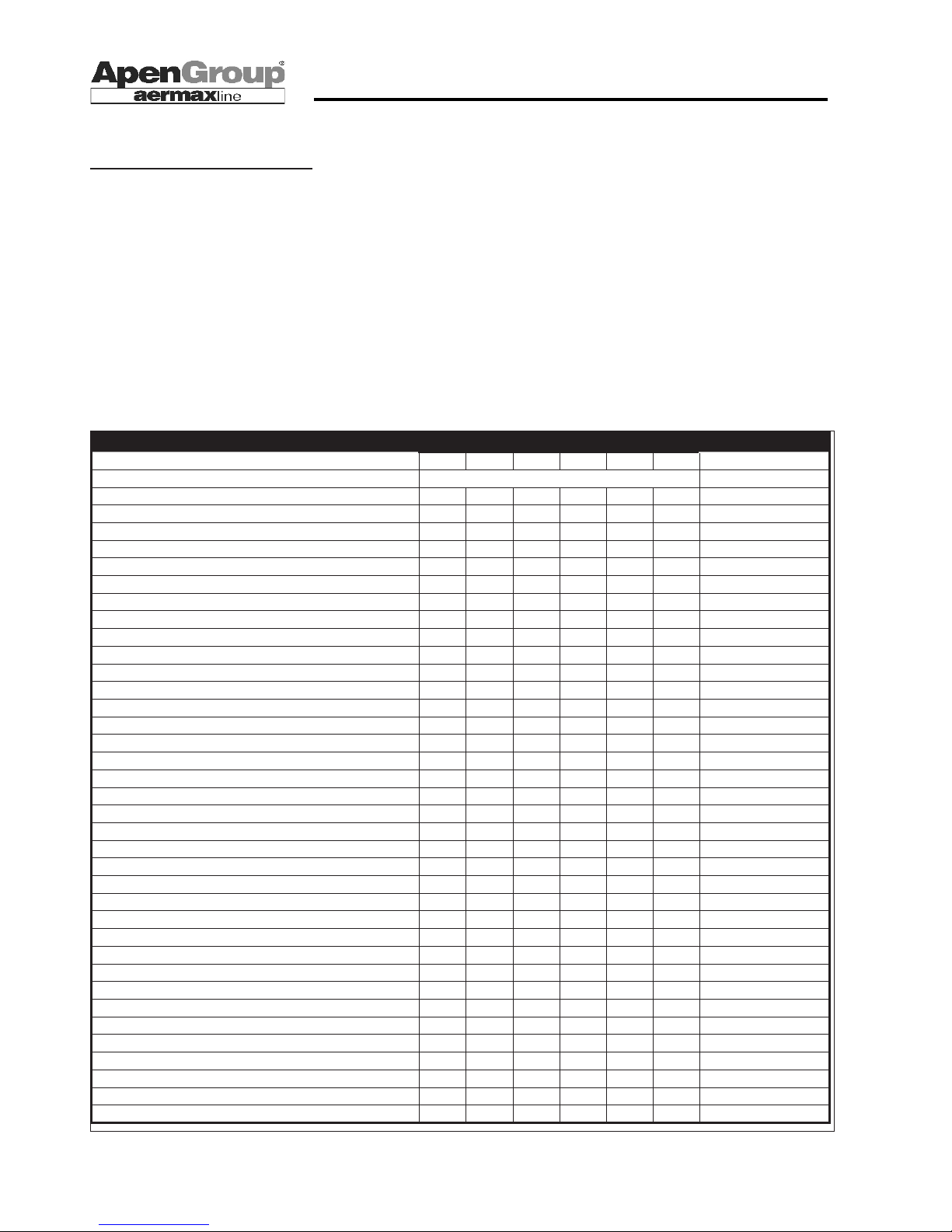
*Equivalent length for wide radius elbows.
** The loss refers to one meter of pipe. When you specify the code, indicate the length in cm instead of xxx.
HG0109.12_ET_008
Guidelines to Component Selection
The following table lists pressure drops of more commonly used
terminals and piping.
If the terminal is not directly connected to the heater and a
distance is to be covered, check that diameters of terminals,
extensions and elbows are correct.
Refer to the table below to assess pressure drops for each
component according to the heater model that was chosen.
Sum pressure drops of each component and make sure the
result does not exceed the available value for the heater to
use. If an air intake pipe is used, sum its pressure drop to that
of ue outlet.
If the result is higher, use pipes with larger diameter and check
again the sum. A pressure drop higher than the pressure avai-
lable on ue system would reduce the thermal power output
of the heater.
Note: The gures in the following pages show examples of
venting and air intake piping built using standard kits. The table below shows maximum lengths of layouts that can be built
between the unit and the terminal. If elbows are included in the
layout, the equivalent length of each elbow must be deducted
from the available length.
Elbow Ø 80 90° EL 1.7 m
Elbow Ø 80 45° EL 0.8 m
Elbow Ø 100 90° EL 1.9 m
Elbow Ø 100 45° EL 0.9 m
Heater Model RA015 RA024 RA032 RA035 RA043 RA054
Pressure available at discharge 50 50 90 90 11 0 110 [Pa]
Component Pressure Drop [Pa] Code
Ø 80 horizontal separate C13 terminal 2,9 4,5 6,2 7,3 10,1 13,9 TC13-08-HS3
Ø 80 horizontal C13 separate terminal + adapter Ø100 3,3 5,7 8,2 9,7 13,7 19,3 TC13-08-HS3M
Ø 100/100 horizontal C13 separate terminal 2,4 2,9 3,4 3,8 4,5 5,9 TC13-10-HS3
Ø 80/80 horizontal C13 concentric terminal 5,5 14 23 28 42 62 TC13-08-HC3
Ø 100/100 horizontal C13 concentric terminal 2 5,5 10 13 21,8 34,5 TC13-10-HC3
Ø 100/100 horizontal C13 concentric terminal (small) 2,4 6,7 12 15,4 25,4 39,9 TC13-10-HC3R
Ø 130/130 horizontal C13 concentric terminal 1 2 2,8 3,5 4,9 7 TC13-13-HC3
Ø 130/130 horizontal C13 concentric terminal (small) 1,2 2,6 4 4,9 7,1 10,2 TC13-13-HC3R
Ø 80/80 horizontal C33 concentric terminal 5,5 14 23 28 42 62 TC33-08-VC1
Ø 100/100 vertical C33 concentric terminal 2 5,5 10 13 21,8 34,5 TC33-10-VC3
Ø 100/100 vertical C33 concentric terminal (small) 2,4 6,7 12 15,4 25,4 39,9 TC33-10-VC3R
Ø 130/130 vertical C33 concentric terminal 1 2 2,8 3,5 4,9 7 TC33-13-VC3
Ø 130/130 vertical C33 concentric terminal (small) 1,2 2,6 4 4,9 7,1 10,2 TC33-13-VC3R
Ø80 B23 horizontal terminal 1,5 2,4 3,4 4 5,6 7,8 TB23-08-HS0
Ø80 horizontal intake only 1,4 2,1 2,8 3,3 4,5 6,1 TC00-08-HS0
Ø100 horizontal B23 terminal 1,2 1,5 1,8 2 2,4 3,2 TB23-10-HS0
Ø100 horizontal intake only 1,2 1,4 1,6 1,8 2,1 2,7 TC00-10-HS0
Ø80 vertical B23 terminal 3,4 5,8 8,6 10,1 14,2 20,1 TB23-08-VS0
Ø100 vertical B23 terminal 2,5 3,4 4,3 4,9 6,2 8,4 TB23-10-VS0
Ø80 pipe ** 0,5/m 1,4/m 2,4/m 3/m 4,6/m 6,8/m G15820-08-xxx
Ø100 pipe ** 0,2/m 0,5/m 0,8/m 1/m 1,4/m 2,2/m G15820-10-xxx
Ø80 elbow wide radius 90° 0,9 2,4 4,1 5,1 7,6 11,3 G15810-08-90
Ø80 elbow wide radius 45° 0,5 1,2 2 2,5 3,8 5,7 G15810-08-45
Ø100 elbow wide radius 90° 0,3 0,9 1,5 1,9 2,8 4,2 G15810-10-90
Ø100 elbow wide radius 45° 0,2 0,4 0,7 0,9 1,3 2 G15810-10-45
Adapter Ø80 - 80/100 0,2 0,6 1 1,2 1,8 2,7 G15815-08-10
Adapter Ø80 - 100/80 0,2 0,6 1 1,2 1,8 2,7 G15815-10-08
Adapter Ø100/130 0,1 0,3 0,6 0,7 1,1 1,6 G15815-10-13
Adapter Ø130/100 0,1 0,3 0,5 0,6 0,9 1,3 G15815-13-10
Horizontal and vertical Ø80 condensate manifold 0,8 0,8 0,8 0,8 0,8 0,8 G15825-08-HV
Horizontal and vertical Ø100 condensate manifold 0,8 0,8 0,8 0,8 0,8 0,8 G15825-10-HV
Ø80 rain protection 2 2 2 2 2 2 G15830-08-V
Ø100 rain protection 1,5 1,5 1,5 1,5 1,5 1,5 G15830-10-V
Ø130 rain protection 1 1 1 1 1 1 G15830-13-V
Ø80 grid 1 1 1 1 1 1 C04787
Ø100 grid - - - - - - G14513
Page 19
Page 19
APEN GROUP reserves the right to change products and documents as required.
code HG0109.12GB ed.C-1106 rev.12
WARM AIR HEATER SERIES RAPID
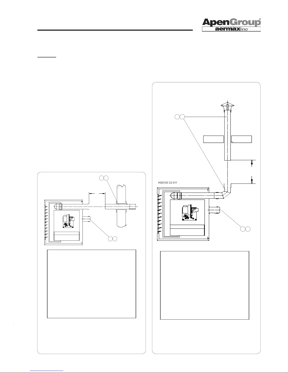
HG0109.12_ET_009
Terminal includes:
-Straight pipe L=900mm with grid
-Outer and inner wall plates
-Fastening accessories
B23 TYPE horizontal
HG0103 C2 011
Terminal includes:
-Rain protection
-Male/female extension L=1000mm
-Elbow 90°
B23 TYPE vertical
L1
15
14
29
28
L1
12
10
29
28
HG0103 C2 010
Max L1 of layout,
terminal excluded
Terminal Ø80 TB23-08-HS0
Pipes and elbows Ø80
Model meters
RA015 30
RA024 30
RA032 29
RA035 26
RA043 22
RA054 17
Max L1 of layout,
terminal excluded
Terminal Ø80 TB23-08-HS0
Pipes and elbows Ø80
Model meters
RA015 29
RA024 29
RA032 26
RA035 24
RA043 20
RA054 15
HG0109.12_ET_009-A
5.4 Terminal Layout
B23 TYPE
Open combustion circuit, combustion air intake from indoor, ue
are exhausted outdoor. In this case, UNI-CIG 7129 and 7131
rules require that suitable openings in the walls are provided.
REMARK: This layout requires an IP20 protection grid to be
installed. The grid [locations 28 and 29] must have a minimum
pitch of 8 mm and must prevent the inlet of any object with a
diameter greater than 12 mm into air intake.
Page 20
Page 20
code HG0109.12GB ed.C-1106 rev.12
APEN GROUP reserves the right to change products and documents as required.
WARM AIR HEATER SERIES RAPID
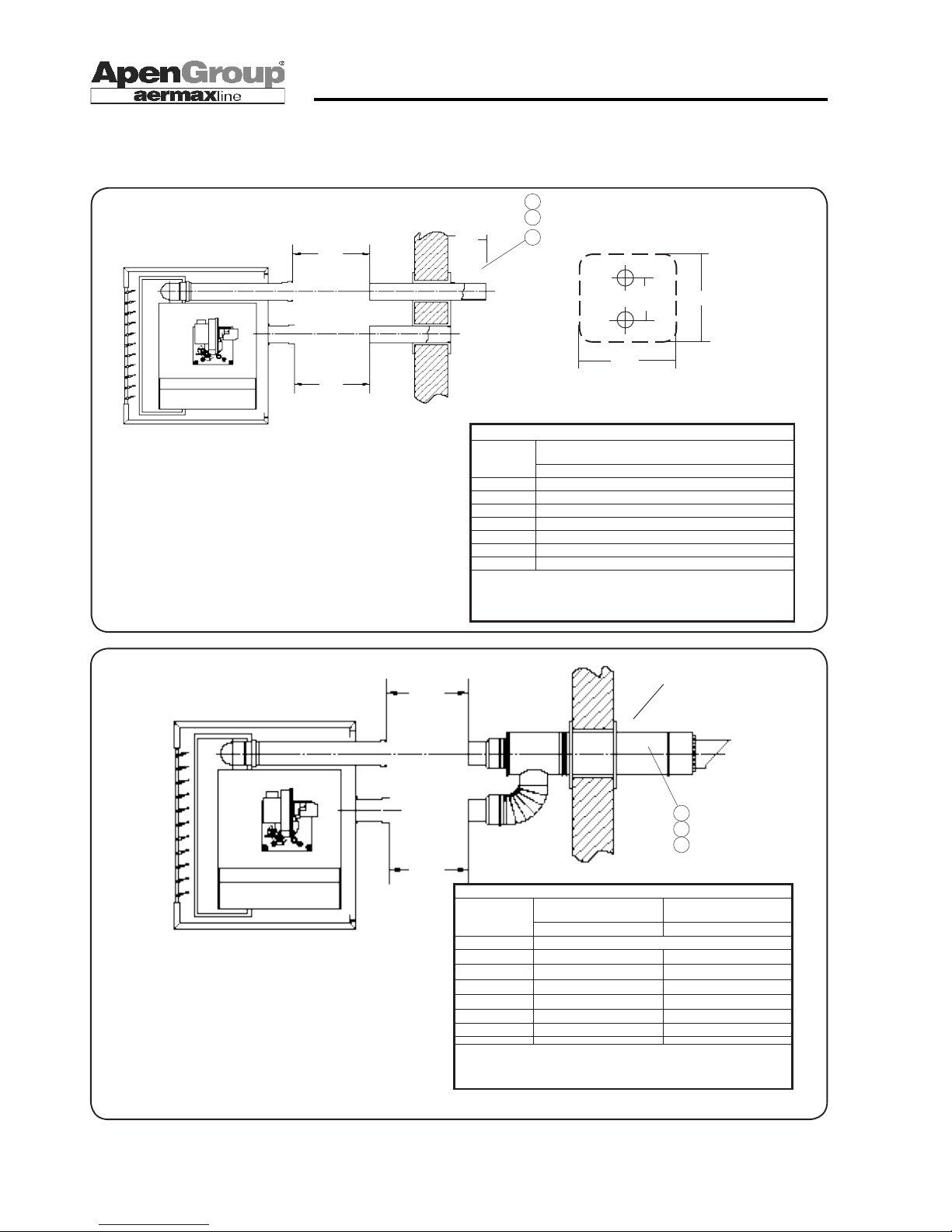
Terminals include:
• TC13-08-HS3
-Intake and ue straight pipes Ø80/80 with grid
-Outer and inner wall plates
-Fastening accessories
L1
L2
6
5
4
HG0103 C2 013
80/80->Ø125
100/100->Ø150
130/130->Ø200
HG0109.12_ET_011
C13 TYPE independent horizontal
C13 TYPE, Combustion circuit sealed from the room. Pipes go outdoor through the wall.
2
1
HG0109.12_ET_010
HG0103 C2 012
160
500
500
3
203
C13 TYPE concentric horizontal
** using Ø80/100 MALE/FEMALE ADAPTERS AND Ø100 PIPES
L2
L1
Max L1 + L2 of layout, terminal excluded
Term. Ø80/80
TC13-08-HC3 Term. Ø100/100 TC13-10-HC3
Pipes and elbows Ø80 Pipes and elbows Ø100
Model Meters
RA015 10 + 10
RA024 10 + 10
RA032 10 + 10
RA035 9 + 9
RA043 7 + 7 9 + 9**
RA054 4,5 + 4,5 10 + 10**
REMARK: Max possible length was equally divided between intake and discharge.
Different ratios are allowed, provided the maximum value shown in the table is not
exceeded.
Max L1 + L2 of layout, terminal excluded
Term. Ø80/80TC13-08-HS3
Pipes and elbows Ø80
Model meters
RA015 15 + 15
RA024 14 + 14
RA032 14 + 14
RA035 12,5 + 12,5
RA043 10 + 10
RA054 8 + 8
REMARK: Max possible length was equally divided between intake and
discharge. Different ratios are allowed, provided the maximum value
shown in the table is not exceeded.
Terminals include:
• TC13-08-HC3
- Terminal including 0uter and inner wall plates, Ø 80/80 back ttings
• TC13-10-HC3
- Terminal including outer and inner wall plates, back ttings
Page 21

Page 21
APEN GROUP reserves the right to change products and documents as required.
code HG0109.12GB ed.C-1106 rev.12
WARM AIR HEATER SERIES RAPID
** using Ø100/80 male/female adapters
*** using Ø80/100 male/female adapters
L2
L1
Terminals include:
• TB23-08-VS0 -Rain protection Ø80
-Extension Ø80 L=1000mm
-Elbow Ø80 90°
• TC00-08-HS0 -Intake terminal Ø80 with grid
-Outer and inner wall plates
-Fastening accessories
• TB23-10-VS0 --Rain protection Ø100
-Extension Ø100 L=1000mm
-Elbow Ø100 90°
• TC00-10-HS0 --Intake terminal Ø100 with grid
-Outer and inner wall plates
-Fastening accessories
15
14
13
11
HG0103 C2 015
C53 TYPE Sealed combustion circuit from the room. Pipe systems are connected one to the roof and the
other to the wall.
HG0109.12_ET_012
Max L1 + L2 of layout, terminal excluded
Discharge Ø80 TB23-
08-VS0
Intake Ø80 TC00-08-HS0
Discharge Ø100 TB23-08-
VS0
Intake Ø100 TC00-08-HS0
Pipes and elbows Ø80 Pipes and elbows Ø100
Model Meters
RA015 14 + 14
RA024 13 + 13
RA032 13 + 13
RA035 11,5 + 11,5
RA043 9 + 9
RA054 7 + 7 12,5 + 12,5***
REMARK: Max possible length was equally divided between intake and
discharge. Different ratios are allowed, provided the maximum value shown in
the table is not exceeded.
Page 22
Page 22
code HG0109.12GB ed.C-1106 rev.12
APEN GROUP reserves the right to change products and documents as required.
WARM AIR HEATER SERIES RAPID
L2
L1
** using Ø80/100 male/female eccentric adapters code G15835-08-10
(to be ordered separately)
Terminals include:
• TC33-08-VC1 - Complete terminal, Ø 80/80 ttings - Centre distance 120
• TC33-10-VC2 - Complete terminal, Ø 100/100 ttings - Centre distance 140
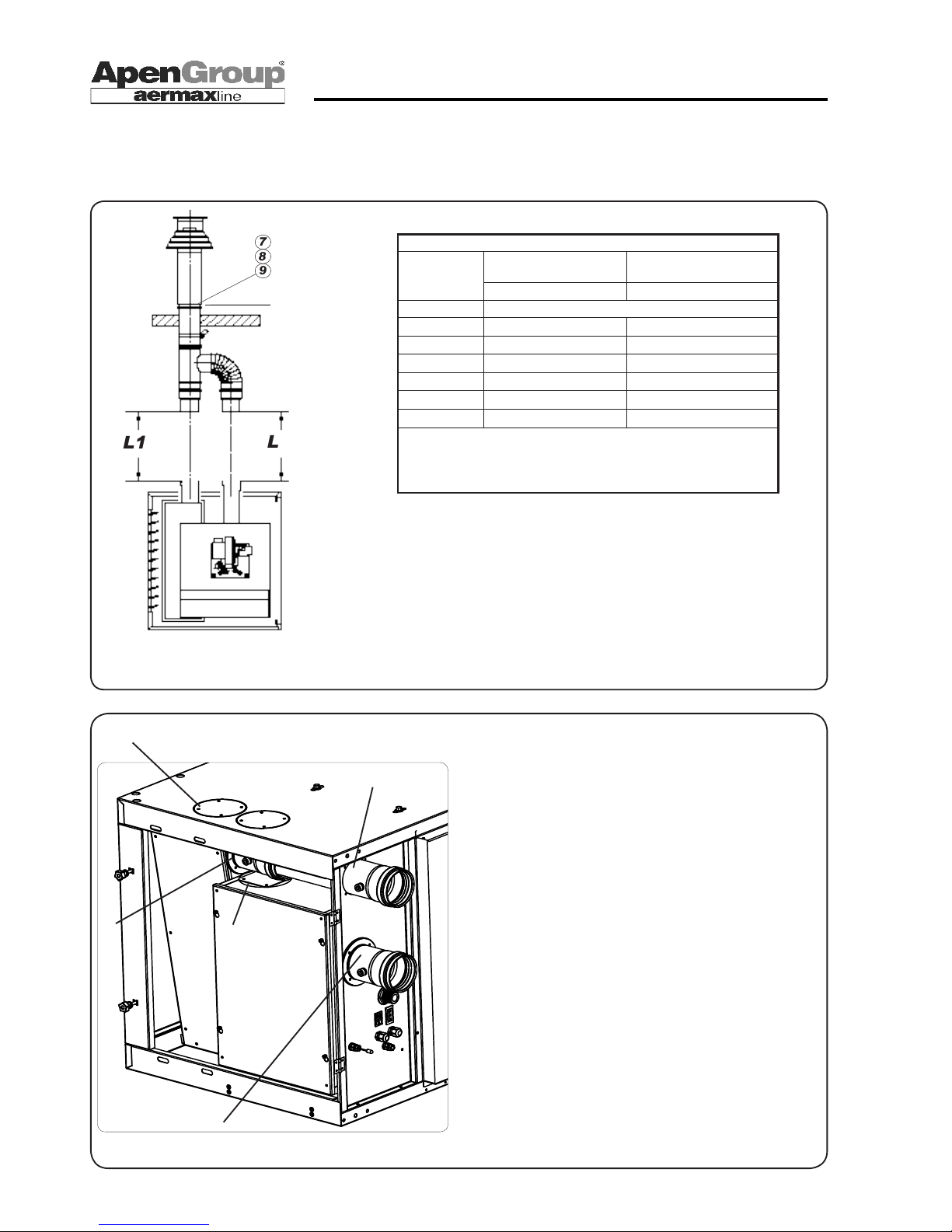
9
8
7
This layout requires that ttings be moved from the back to the top of the
heater. For more details, see instructions below.
HG0103 C2 016
To disassemble:
1) Cut "A" covers from upper panel
2) Pull "C" ue pipe
3) Disassemble the intake joint "D"
4) Disassemble the ue joint "B"
5) Remove internal covers "E" installed one on burner casing
and the other over ue hood
How to assemble:
1) Install one "E" cover (and its seal) on the side hole of the
exchanger.
2) Install "B" ue junction on upper hole of the exchanger
3) Insert intake junction "D" on burner compartment
4) Cut to length "C" pipe and install it on "D" air junction
reaching same height as ue outlet
5) Install pre-cut covers "A" and their seals on the hole for
air intake
6) Install "E" cover without seal on back hole of the ue
Disassembling
Assembling
80/80->Ø125
100/100->Ø150
130/130->Ø200
HG0109.12_ET_012
A
B
C
D
E
HG0109.12_C2_009
C33 TYPE (ROOF)
Combustion circuit is sealed from the room. Pipes end outdoor with a
concentric terminal.
Max L1 + L2 of layout, terminal excluded
Term. Ø80/80
TC33-08-VC1 Term. Ø100/100 TC33-10-VC2
Pipes and elbows Ø80 Pipes and elbows Ø100
Model meters
RA015 11 + 11
RA024 11 + 11
RA032 10 + 10
RA035 9 + 9
RA043 7 + 7
RA054 4,5 + 4,5 10 + 10**
REMARK: Max possible length was equally divided between intake and discharge. Different ratios
are allowed, provided the maximum value shown in the table is not exceeded.
Page 23
Page 23
APEN GROUP reserves the right to change products and documents as required.
code HG0109.12GB ed.C-1106 rev.12
WARM AIR HEATER SERIES RAPID
5.5 Electrical Wiring
HG0109.12_C2_005
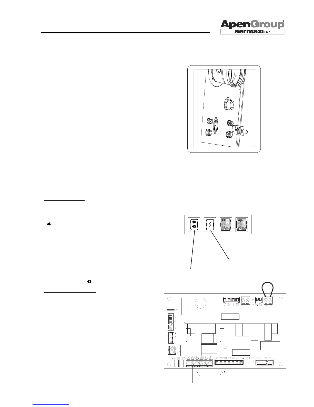
Room Thermostat Wiring
It is mandatory to install a room thermostat or a timer to turn
the burner off without powering off the unit. No spare jumper
supplied with the heater.
Connect the thermostat to terminals No. 34 and 35 of the
board on the electronic card installed into the control panel
housing of RAPID heater (it replaces the jumper, see diagram
in this page).
If the burner can be turned off by multiple switches, they must
be wired in series.
A remote button can be installed and wired to terminals No.
29 and 30 of the board [WARNING: current is 230V].
The type of the button must be Normally Open.
.
Power Supply
The heater shall be properly wired to an efcient grounding
system, complying with existing regulations.
Single-phase 230 Vac supply with neutral. Do not mistake
neutral and phase wires If phase and neutral wires are
exchanged, the unit will automatically lock.
The heater can be plugged into mains using a plug-socket
only if the latter prevents any mistake between phase and
neutral wires.
The system wire gauge in general, and cable section in particular, must suit the unit rated input (see technical data table).
Keep cables far from heat sources.
REMARK: A multipole cut-out switch must be installed
before the heater with suitable electric protection.
The section of supply cables must be at least 1.5 mm²
The unit shall be plugged into the mains using the plug supplied. Always unplug the unit during maintenance operations.
Reset button
Summer Ventilation
You can enable only the fans (summer ventilation while the
burner is off) in the following ways:
1) Turn the switch on the heater on
" =SUMMER". In this way, the fans can be turned on or
off by rotating the switch or by powering off the appliance (this
latter is not allowed in Winter mode).
2) Use remote control - see G12800 and G00094 accessories
3) Remotely control the CN3 connector command through
terminals No. 34,35, and 36 as indicated in the wiring diagram
for G12800 accessory [see diagram in the following page].
When the summer ventilation command is remotely controlled,
the switch on the heater shall be turned on " =WINTER".
HG0109.09_C2_007
Summer /0 /Winter switch
HG0109.12 C2 001
RESET
ROOM
THERMOSTAT
Page 24
Page 24
code HG0109.12GB ed.C-1106 rev.12
APEN GROUP reserves the right to change products and documents as required.
WARM AIR HEATER SERIES RAPID
HG0100 C2 012
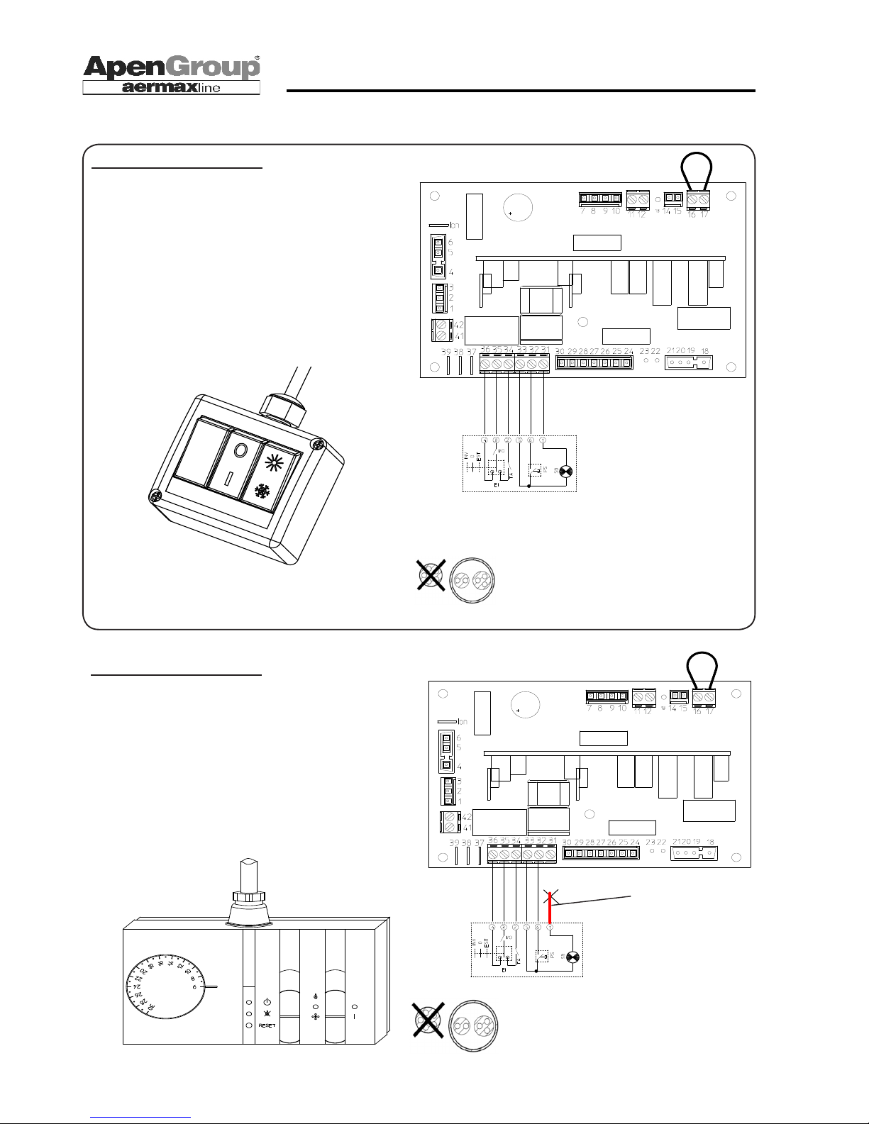
Wiring G12800 remote control
G12800 remote control includes an I/O switch, a summer/
winter switch, a reset and lock signaling LED and is delivered
with a multipole, numbered cable already wired.
To wire the control to the heater, do the following:
- Wire remote control numbered wires (1 to 6) to 31-36 terminals
of relevant board (see diagram in this page).
- Make sure the summer/winter switch installed on the heater
is turned on "I=WINTER".
HG0109.12 C2 003
Wiring G00094 remote control
G00094 remote control includes a room thermostat, a summer/
winter switch, a reset and lock signaling LED and is delivered
with a multipole, numbered cable already wired.
To wire the control to the heater, do the following:
- Wire remote control numbered wires (2 to 6) to 31-36 terminals
of relevant board (see diagram in this page).
- Make sure the summer/winter switch installed on the heater
is turned on "I=WINTER".
HG109.12 C2 002
REMARK: Do not use a multipole cable
conducting both electrical supply and
chronothermostat control, since this would
interfere with control signals, jeopardizing
heater operation.
DO NOT CONNECT
AND
ISOLATE POWER
CABLE
REMARK: Do not use a multipole cable
conducting both electrical supply and
chronothermostat control, since this would
interfere with control signals, jeopardizing
heater operation.
HG0109.12_C2_026
Page 25
Page 25
APEN GROUP reserves the right to change products and documents as required.
code HG0109.12GB ed.C-1106 rev.12
WARM AIR HEATER SERIES RAPID
5.6 Gas Supply System
For this system, use CE-approved and certied components only.
RAPID heaters are supplied with
a double gas valve
and a gas lter and stabilizer already installed.
All components are assembled into the burner compartment.
To complete installation in compliance with the law, the installer
shall install the following components:
- Vibration damping joint
- Gas cock
We recommend installing a gas lter with a high ow rate and
no pressure stabilizer. In fact, the standard lter installed before
the gas valve has a limited surface.
Do not use threaded joints directly on gas tting. A vibration
damping joint with seat lift on heater side is to be preferred, in
order to ease maintenance.
The law allows a maximum pressure of 40 mbar inside the
building or thermal plant. Higher pressure values shall be reduced
before the room where the heater is installed.
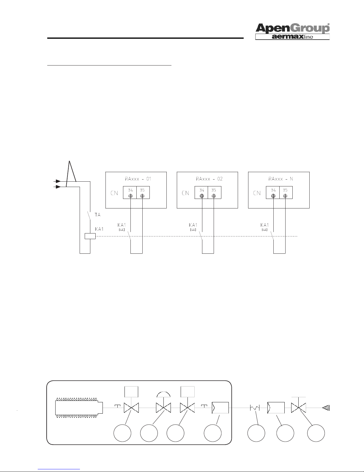
LEGEND
1 Main burner gas solenoid valve
2 Pressure stabilizer
3 Safety solenoid valve
4 Gas lter (small section)
5 Vibration damping joint
6 Gas lter (large section)
7 Gas cock
Supplied with RAPID heater
1 2 3 4 5 6 7
To be installed by the installer
HG0109 C2 006
Connecting Multiple Heaters to One Remote Control
If you need to connect multiple RAPID heaters to just one
thermostat, chronothermostat or timer, make sure the following
conditions are met:
- Each unit must have its own unpowered contact wired to
terminals No. 34 and 35 of the board.
-The load capacity of this contact must be 4A at 250V
- Do not wire in parallel multiple units to just one contact
- Let I/0/II switch on the unit turned on "I=WINTER".
LEGEND:
- TA Room thermostat or chronothermostat
- KA1 Auxiliary contactor
- RAxxx RAPID heater
- CN3 RAPID heater connector
HG0109.12_C02_017
EXTERNAL POWER SUPPLY
BASED ON CONTACTOR COIL
Page 26
Page 26
code HG0109.12GB ed.C-1106 rev.12
APEN GROUP reserves the right to change products and documents as required.
WARM AIR HEATER SERIES RAPID
6. INSTRUCTIONS TO SERVICE STAFF
First start-up must be performed by an APEN GROUP Authorized Service Centre.
During rst start up, the combustion efciency must be analyzed.
This appliance is certied for EC and Extra-EC countries for the gas categories listed below.
6.1 Country Table - Gas Category
HG0109.12_ET_014
On the packaging of each heater the following information are clearly marked: Destination Country, gas category, and appliance
code translated into the language of destination Country.
The code shows the factory setting for the unit:
Codes without extension:
- RA043IT no extension means that the unit has been set and tested for using natural gas [G20]
Codes with extension:
the fourth letter identies the gas for which the unit has been set:
- RA043FR-xxx0 0 indicates the unit has been set and tested for natural gas [G20]
- RA043MT-xxx1 1 indicates the unit has been set and tested for Liquid Propane [G31]
- RA043NL-xxx2 2 indicates the unit has been set and tested for natural gas 'L’ [G25]
- RA043HU-xxx3 3 indicates the unit has been set and tested for natural gas [G25.1]
- RA043PL-xxx4 4 indicates the unit has been set and tested for [G2.350] gas
Another label on the unit, placed near fuel supply, clearly states which gas type and supply pressure the unit has been set and
tested for.
County Category Gas Pressure Gas Pressure
AT II2H3B/P G20 20 mbar G30/G31 50 mbar
BE <70kW I2E(S)B,I3P G20/G25 20/25 mbar G31 37 mbar
CH II2H3B/P G20 20 mbar G30/G31 50 mbar
DE II2ELL3B/P G20/G25 20 mbar G30/G31 50 mbar
DK, FI, GR, SE, NO II2H3B/P G20 20 mbar G30/G31 30 mbar
ES, GB, IE, PT, SK II2H3P G20 20 mbar G31 37 mbar
IT, CZ II2H3B/P G20 20 mbar G30/G31 30 mbar
FR II2Esi3P G20/G25 20/25 mbar G31 37 mbar
LU II2E3P G20/G25 20 mbar G31 37/50 mbar
NL II2L3B/P G25 25 mbar G30/G31 30 mbar
HU II2HS3B/P G20/G25.1 25 mbar G30/G31 30 mbar
CY, MT I3B/P G30/G31 30 mbar
EE, LT, SI, II2H3B/P G20 20 mbar G30/G31 30 mbar
AL, MK II2H3P G20 20 mbar G30/G31 37 mbar
LV I2H G20 20 mbar
IS I3P G31 37 mbar
BG, RO, HR, TR II2H3B/P G20 20 mbar G30/G31 30 mbar
PL II2ELwLs3B/P G20/G27/G2.350 20/13 mbar G30/G31 37 mbar
Page 27
Page 27
APEN GROUP reserves the right to change products and documents as required.
code HG0109.12GB ed.C-1106 rev.12
WARM AIR HEATER SERIES RAPID
HG0109.12_ET_015
G20 GAS TYPE
TYPE OF APPLIANCE RA015 RA024 RA032 RA035 RA043 RA054
CATEGORY
Based on target country - see table 6.1
SUPPLY PRESSURE [mbar] 20 [min 17 - max 25] [for Hungary 25 mbar]
Ø GAS DIAPHRAGM [mm] 3,5 5,1 6,5 6,5 8,5 -
Ø AIR DIAPHRAGM [mm] 13,0 18,0 23,0 24,0 28,0 29,0
CARBON DIOXIDE CO
2
[%] 9,1 ±0,2 [cat. H] - 9,3 ±0,2 [cat. E]
GAS CONSUMPTION (15°C-1013mbar) [m3/h] 1,75 2,8 3,68 4,1 5,03 6,14
G25 GAS TYPE [cat L-LL]
TYPE OF APPLIANCE RA015 RA024 RA032 RA035 RA043 RA054
CATEGORY
Based on target country - see table 6.1
SUPPLY PRESSURE [mbar] 25 [min 20 - max 30] [for Germany 20 mbar]
Ø GAS DIAPHRAGM [mm] 3,5 5,1 6,5 6,5 8,5 -
Ø AIR DIAPHRAGM [mm] 13,0 18,0 23,0 24,0 28,0 29,0
CARBON DIOXIDE CO
2
[%] 8,9 ±0,2
GAS CONSUMPTION (15°C-1013mbar) [m3/h] 2,03 3,26 4,28 4,76 5,84 7,13
G30 GAS TYPE
TYPE OF APPLIANCE RA015 RA024 RA032 RA035 RA043 RA054
CATEGORY
Based on target country - see table 6.1
SUPPLY PRESSURE [mbar] 30 [min 25 - max 35] - 50 [min 42,5 - max 57,5]
Ø GAS DIAPHRAGM [mm] 2,5 3,5 5,1 5,1 6,0 6,5
Ø AIR DIAPHRAGM [mm] 13,0 18,0 23,0 24,0 28,0 29,0
CARBON DIOXIDE CO
2
[%] 10,8 ±0,2
GAS CONSUMPTION (15°C-1013mbar) Kg/h 1,06 1,71 2,24 2,49 3,06 3,73
G31 GAS TYPE
TYPE OF APPLIANCE RA015 RA024 RA032 RA035 RA043 RA054
CATEGORY
Based on target country - see table 6.1
SUPPLY PRESSURE [mbar] 30 [min 25 - max 35] - 37 [min 25 - max 45] - 50 [min 42,5 - max 57,5]
Ø GAS DIAPHRAGM [mm] 2,5 3,5 5,1 5,1 6,0 6,5
Ø AIR DIAPHRAGM [mm] 13,0 18,0 23,0 24,0 28,0 29,0
CARBON DIOXIDE CO
2
[%] 9,8 ±0,2
GAS CONSUMPTION (15°C-1013mbar) Kg/h 1,05 1,68 2,21 2,45 3,01 3,68
G25.1 * GAS TYPE [cat Ls] - [only for Hungary]
TYPE OF APPLIANCE RA015 RA024 RA032 RA035 RA043 RA054
CATEGORY
Based on target country - see table 6.1
SUPPLY PRESSURE [mbar] 25 [min 20 - max 30]
Ø GAS DIAPHRAGM [mm] - - - - - -
Ø AIR DIAPHRAGM [mm] 13,0 18,0 23,0 24,0 28,0 29,0
CARBON DIOXIDE CO
2
[%] 10,1 ±0,3
GAS CONSUMPTION (15°C-1013mbar) [m3/h] 2,03 3,26 4,28 4,75 5,84 7,13
G2.350 * GAS TYPE [cat Lw] [only for Poland]
TYPE OF APPLIANCE RA015 RA024 RA032 RA035 RA043 RA054
CATEGORY
Based on target country - see table 6.1
SUPPLY PRESSURE [mbar] 13
Ø GAS DIAPHRAGM [mm] - - - - - -
Ø AIR DIAPHRAGM [mm] 13,0 18,0 23,0 24,0 28,0 29,0
CARBON DIOXIDE CO
2
[%] 8,7 ±0,3
GAS CONSUMPTION (15°C-1013mbar) [m3/h] 2,44 3,93 5,16 5,73 7,04 8,59
6.2 Gas Setting Data Table
Page 28
Page 28
code HG0109.12GB ed.C-1106 rev.12
APEN GROUP reserves the right to change products and documents as required.
WARM AIR HEATER SERIES RAPID
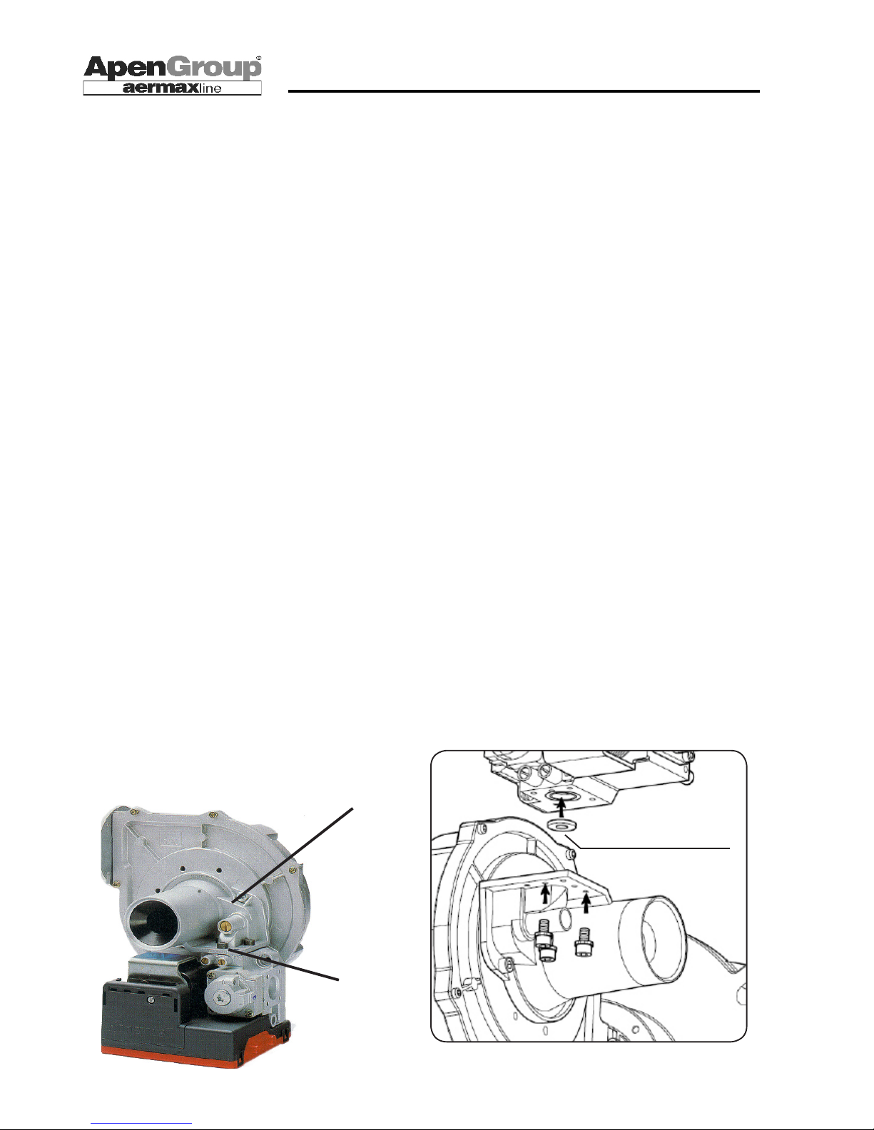
CO2 REGULATION
GAS INLET TAPPING
POINT (IN)
HG0103 IM 003
6.3 First Start Up
First start-up must be performed by an APEN GROUP Authorized Service Centre.
At delivery, the heater is set and tested for using the type of
gas reported on the rating plate. Before starting the heater, go
through the following checklist:
• Make sure the available gas matches the type the heater is
set for.
• Using the “IN” pressure tap on the gas valve, verify that the
inlet pressure to the valve matches the value required for the
type of gas used.
• Make sure electrical wiring match the requirements supplied
in this manual or in other wiring diagrams enclosed with the
delivered unit. Make sure the unit is powered and the green
LED is ON.
• Close the room thermostat contact and make sure that the
switch on the back of the unit is turned on "I=WINTER".
After checking previous conditions, and if the unit is not locked,
the start-up sequence is launched. This sequence includes
pre-washing the furnace, igniting the burner start-up and then
starting cooling fans.
At this stage, the pilot burner is not likely to start because of
air in gas pipes. The heater locks up. Start-up sequence will
be automatically repeated 4 times. After 4 attempts, the heater
locks up (red LED on) and a reset is required to repeat the
start-up sequence.
6.4 Combustion Analysis
Start the unit and check that the inlet pressure to the valve
matches the one required by the gas type. If it doesn't, adjust it.
Wait a couple of minutes, then connect a ue gas content
analyzer to the chimney and check CO2 value, comparing it to
the one listed in the Gas Setting Data (point 6.2) table referred
to the kind of fuel used.
- If this value is not included in the required range, regulate CO2
value by adjusting the screw on the Venturi: turn it clockwise to
decrease gas ow (thereby decreasing also CO2 value), and
counter clockwise to increase it.
6.5 Converting the Unit to LPG
This conversion is strictly forbidden in Countries such as
Belgium, where double category for gas is not allowed.
This Kit is not supplied in Countries where conversion is not
allowed.
The conversion to another type of gas shall be carried out
exclusively by an APEN GROUP certied Service Centre.
The heater is supplied to use natural gas. The kit for converting
it into Liquid Propane is supplied as a standard and includes:
- One calibrated diaphragm
- One sticker "Appliance converted to.."
Once the conversion and the setting have been made, replace
the label "Appliance set for Natural Gas" with the one "Appliance
converted to…", enclosed in the kit.
To convert the heater, do the following:
- Disconnect the unit from power supply
- Replace the supplied calibrated diaphragm between the gas
valve and the Venturi
- Power the heater on and make it ready for start up
When the burner is working, check the following:
1) The inlet pressure to the valve matches the one required
for the gas used
2) The CO2 value does not exceed the values corresponding
to the used gas.
Should the value be different, change it by turning the regulation
screw: screw to decrease the value and unscrew to increase it.
Check again that gas circuit does not leak.
REMARK: The heater supplied for using LPG is adjusted
for G31 gas. In order to use G30, the CO2 value must be
checked and adjusted according to table 6.2, if necessary.
Gas diaphragm replacement
Page 29
Page 29
APEN GROUP reserves the right to change products and documents as required.
code HG0109.12GB ed.C-1106 rev.12
WARM AIR HEATER SERIES RAPID
6.7 MAINTENANCE
To keep the unit perfectly efcient and guarantee its durability,
we recommend to go through the following checklist at least
once a year, before restarting the heater:
1) Check the condition of start-up and detection electrode
2) Check ue and air intake terminals and ducts
3) Check the Venturi
4) Check the exchanger is clean (every 3/4 years)
5) Check the inlet pressure of the gas valve
6) Check the operation of ame control device and air pressure
switch
7) Check the safety thermostat/s
8) Check ionization current
REMARK: Checks in steps 1, 2, 3, and 4 must be carried out
after power and gas supplies have been cut off.
Checks in steps 5, 6, 7, and 8 must be carried out while the
heater is running.
1) Checking the electrodes
Check proper operation of start-up system and detection device
every year.
In case of anomalies, uninstall the electrodes. Check the integrity
of the ceramic and use emery paper to remove any oxidation
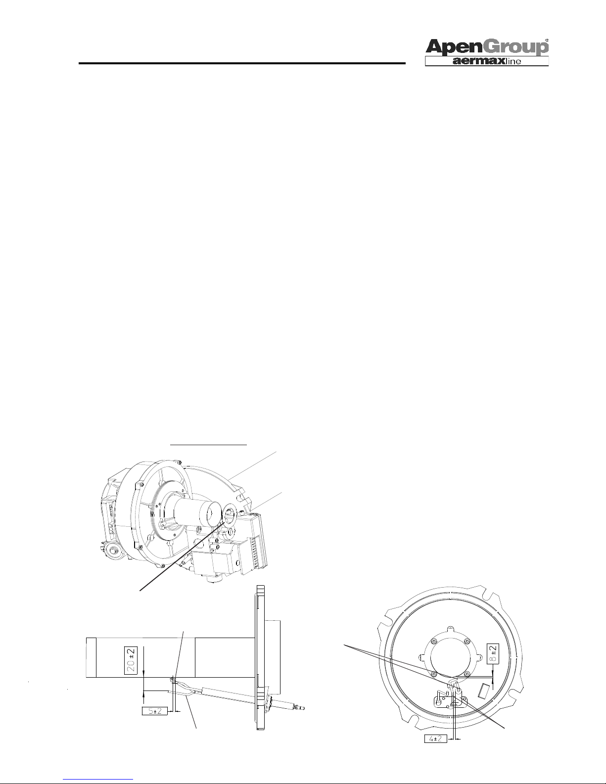
on metal parts of the electrodes. Verify proper position of electrodes (see picture in this page). The detection electrode must
be installed 20 ±2 mm from burner torch. The start-up electrode must release on the outer edge of the burner at a suitable
distance from detection electrode (see diagram underneath).
If the burner is disassembled, check the ceramic ber gasket
and replace it, if necessary.
2) Flue and Air Inlet Systems
Check duct status looking into them or using suitable tools.
Remove dust from air intake terminal.
3) Checking and cleaning the Venturi
If necessary, use a brush to remove dust on the Venturi inlet,
taking care not to let it drop inside.
6.6 Conversion to G25 - G25.1 - G2.350 Gas
The conversion to another type of gas shall be carried out
exclusively by an APEN GROUP certied Service Centre.
Conversion from G20 into G25 is only allowed for Countries
in Cat. 2
ELL
[Germany] and in Cat. 2HS [Hungary].
The conversion to G25 gas, if possible, does not require
any change for the heater. The only exception is the RA054
model, where the gas diaphragm is to be removed.
The conversion to G25.1 gas (Hungary only) requires the
removal of gas diaphragm from all models of RA series.
In Countries in Cat. "2L" [Holland], the unit is supplied set
and tested for G25.
For Cat. 2E Countries [France, Belgium and Luxembourg]
where conversion from G20 to G25 is not allowed the appliance is supplied already set to use both G20 and G25
gases. Therefore, conversion is not needed.
Conversion to G2.350 gas is allowed only in Poland.
The conversion to G2.350 gas requires the removal of gas
diaphragm from all models of RA series.
After completing the conversion, turn the burner on and:
- Check that CO2 value does not exceed the accepted range
for gas type [see table 6.2]. If it does, change it by turning the
Venturi adjustment screw: screw to decrease and unscrew
to increase.
Stick the label "Appliance converted to G25 gas" over the
previous label "Appliance set for ... ".The new sticker is
enclosed in the kit.
Special care should be paid to COCO2 value of G25.1 gas.
Electrodes
must
be parallel
External edges
must
coincide
Start-up electrode
Detection electrode
HG0109.11 C2 004
HG0109.12_C2_027
Air Diaphragm
Page 30
Page 30
code HG0109.12GB ed.C-1106 rev.12
APEN GROUP reserves the right to change products and documents as required.
WARM AIR HEATER SERIES RAPID
Detection electrode
Bottom view of the burner
DC Micro Ammeter
Flame control
device
HG0109.12_C2_007
Start-up electrode
A
4) Checking and cleaning the exchanger (every 3/4 years)
Optimal combustion efciency in RAPID heaters prevents residual combustion products. However, in time, some dirt could
settle inside exchanger pipes, due to the ne dust drawn through
the combustion air duct. It is not possible to schedule a precise
timetable for cleaning the heat exchanger. A sensible decrease
in gas ow could indicate there is dirt inside the heat exchanger.
5) Inlet Gas Pressure
Check that the inlet pressure to the valve corresponds to the
one required for the available gas.
This check is to be carried out while the heater is running at
maximum capacity.
6) Flame Control Device
While the heater is running, close the gas tap and verify that
the unit locks. Reopen gas tap, reset, and wait for the heater
to restart.
7) Safety thermostat/s
Run this test while the heater is working.
Heat the thermostat bulb using a hot air gun or a gas lighter and
check that the unit locks. Cool the bulb, then reset: this procedure
must be carried out on each thermostat assembled on the unit.
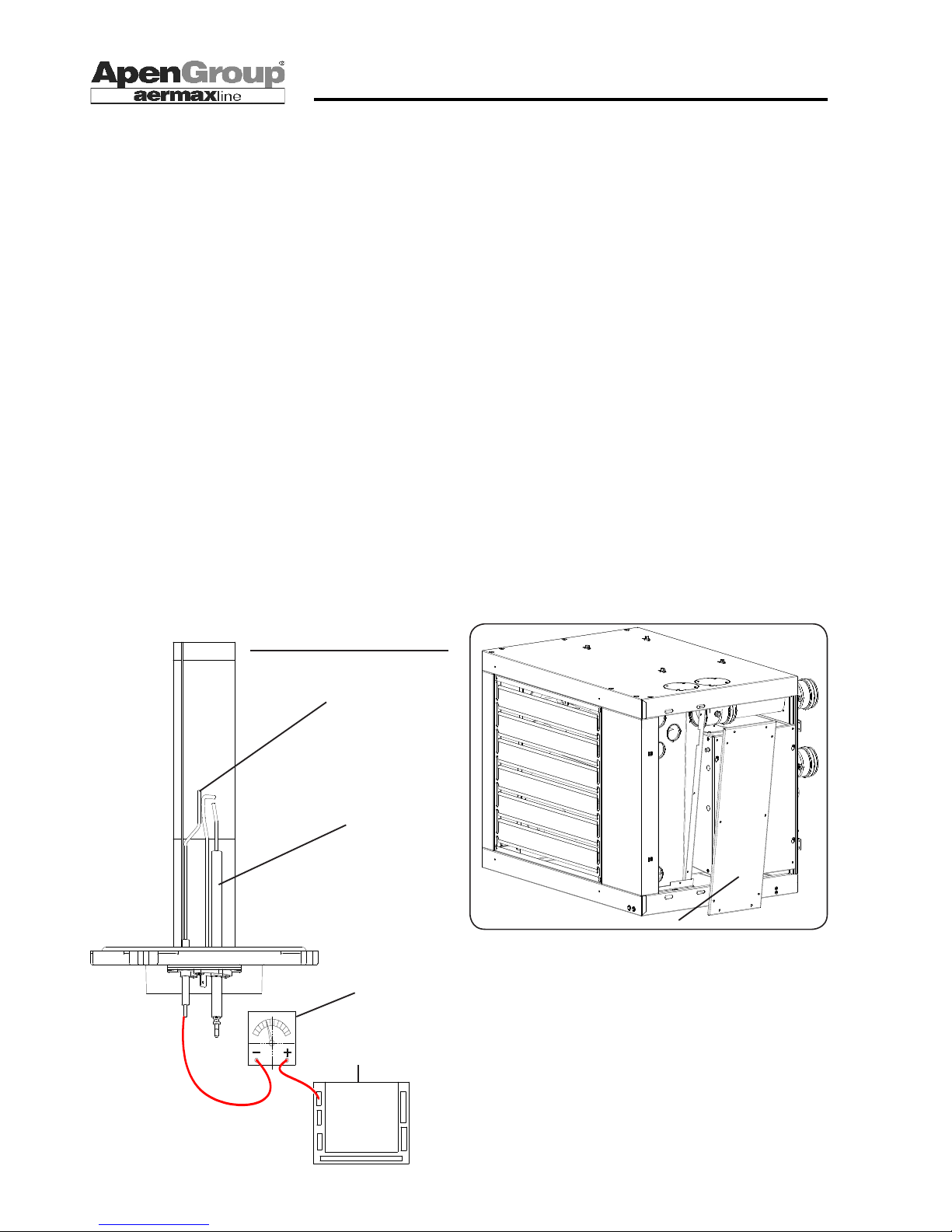
8) Ionization Current
Carry out this operation using a device capable of testing direct
current microamperes. Do the following:
- Disconnect the unit from power supply.
- Disconnect ame control device cable and connect it to the
negative pole of the tester.
- Use a wire to connect the positive pole of the tester and the
ame control device of the unit.
- Power on the device and wait for the burner to start up.
- Check ionization value.
This value must not be lower than 2 micro Amperes. Lower
values would indicate that the detection electrode is misplaced,
oxidized or it is going to break down.
6.8 Cleaning the Exchanger
The following operations must be carried out when the unit is
cold and disconnected from power supply:
• Open the heater door.
• Disconnect the unit from power supply
• Remove the screws that x the ue hood cover.
• Use a suitable brush to clean pipes all along their length,
pushing dirt towards the outlet to collect it.
• Re-install the ue hood cover, taking care to check components
remain sealed.
6.9 Demolition
Should the unit be dismantled or demolished, please take care to:
• remove wires and cables;
• remove all plastic components.
Note: Any recovered material shall be treated and disposed
of according to existing regulations and/or rules given in
safety technical sheets accompanying chemical products.
Page 31
Page 31
APEN GROUP reserves the right to change products and documents as required.
code HG0109.12GB ed.C-1106 rev.12
WARM AIR HEATER SERIES RAPID
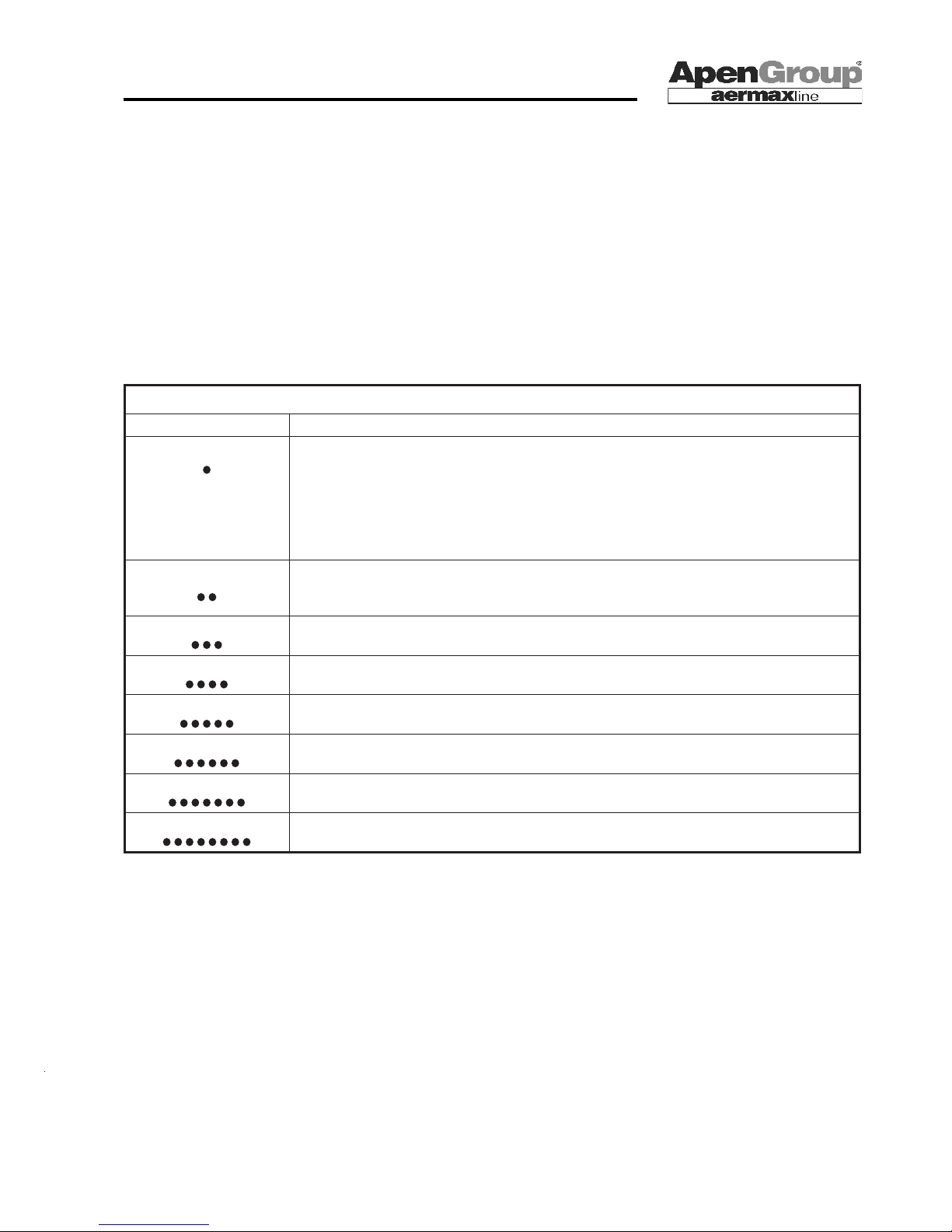
7. DIAGNOSTICS
Heaters include a diagnostic system that is activated in case of ill functioning. A steady red LED lights up on heater front panel
when a fault occurs.
To reset the fault, press RESET button for more than 1 sec. RESET button is on front panel (see gure on page 21).
Maximum number of RESET attempts allowed is 3. If the failure persists, call Service Center for assistance.
To activate diagnostics and nd out fault type, press RESET button for more than 5 secs. Red LED will start ashing in sequences separated by a pause of 2 secs. The number of ashes in each sequence indicates the fault number. Check in the following
table fault numbers and relevant meaning.
Fault Codes Meaning
Number of ashes Possible reason
1. Flash
No detection of ame signal and timeout of safety card exceeded:
- Detection electrode wrongly positioned
- No fuel
- Fuel valves not working properly
- Faulty start-up transformer
- Burner damper wrongly set
2 Flashes
Safety Thermostat Opening:
- Activation of Safety Thermostat
- Faulty Safety Thermostat
3 ashes
Not applicable
4 ashes
Not applicable
5 ashes
Faulty Hall sensor of Burner Motor:
- Motor revolutions per minutes are less than set value
6 ashes
Secondary ames at startup
7 ashes
Not applicable
8 ashes
Generic fault
Page 32
Page 32
code HG0109.12GB ed.C-1106 rev.12
APEN GROUP reserves the right to change products and documents as required.
WARM AIR HEATER SERIES RAPID
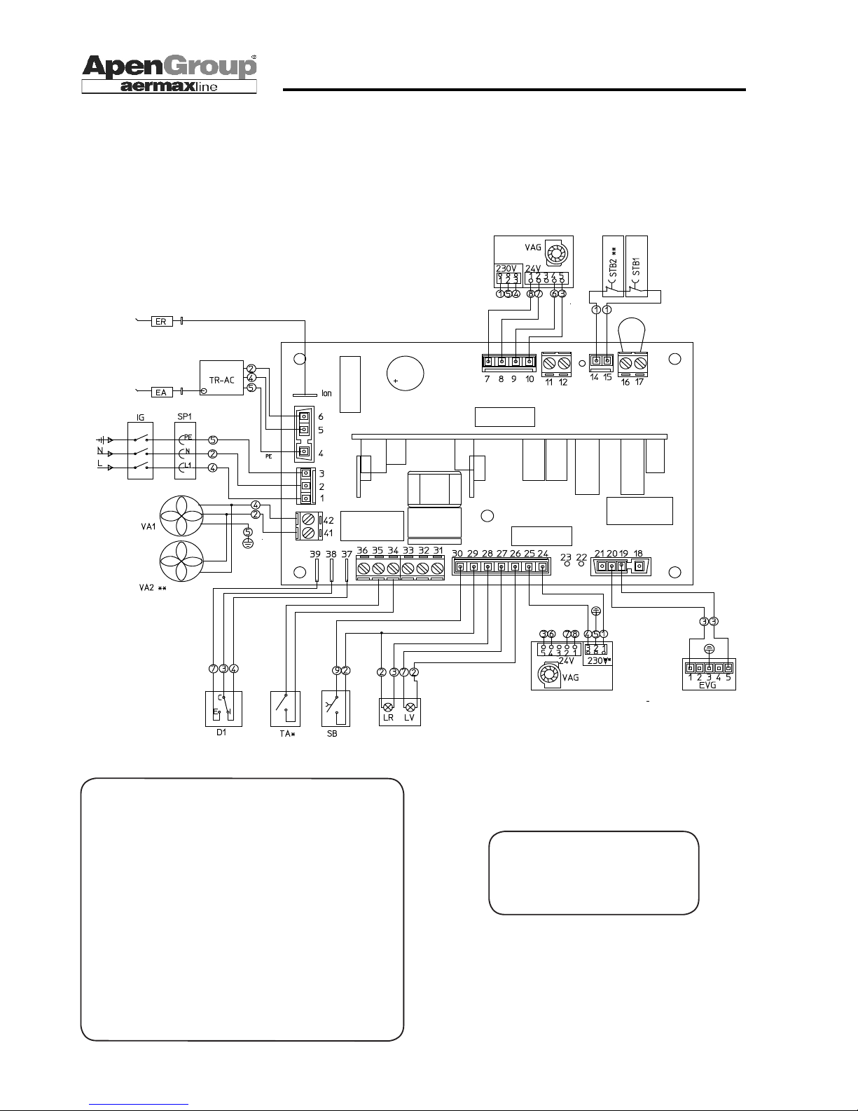
8. WIRING DIAGRAM
RA015 - RA054 Wiring Diagram (code JG0400.00)
For connections, see section on Installation.
Component Legend
IG Voltage disconnect switch (not included)
SP1 Socket/plug to power the unit
ACF Flame control device
EVG Gas solenoid valve
STB1-2 Safety thermostat (manual reset).
TR-AC Start-up transformer
EA Start-up electrode
ER Detection electrode
TR 230/24V - 63 VA transformer
VAG Burner fan
LV Green LED 230V [unit powered]
LR Red LED 230V [lock]
D1 Summer/winter switch
SB Reset Button
SB Air fans
F1 4 AT fuse on board (delayed)
R1 Relays of air fans
Wire colors
1 BLACK 2 BLUE/LIGHT BLUE
3 RED - ROSE 4 BROWN
5 YELLOW/GREEN 6 GREY
7 GREEN 8 WHITE
9 ORANGE
Page 33
Page 33
APEN GROUP reserves the right to change products and documents as required.
code HG0109.12GB ed.C-1106 rev.12
WARM AIR HEATER SERIES RAPID
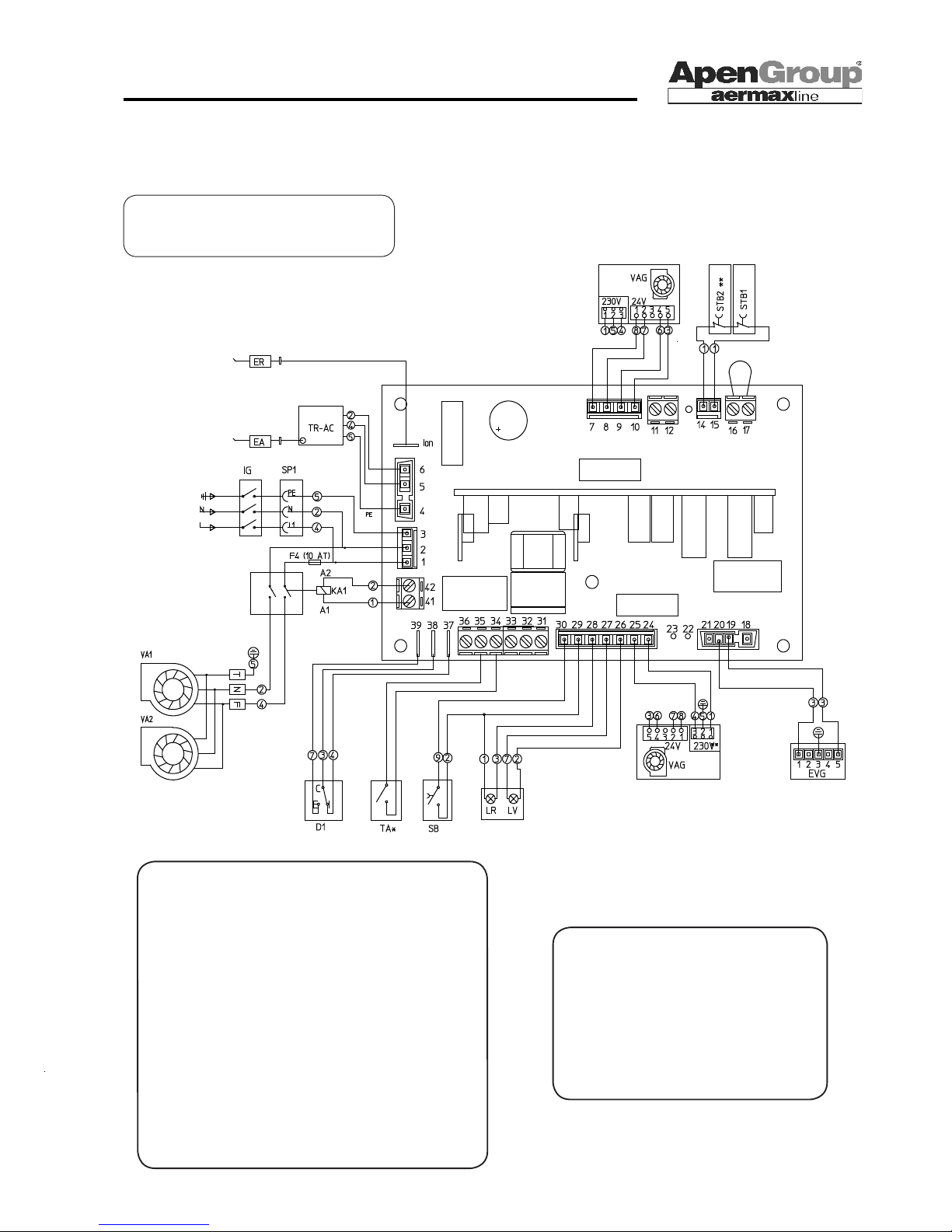
NOTES:
- Dotted lines of fan burner wirings [VAG] are
only valid for RA054 model
- VA2, STB2 and R1 components are only for
RA043 and RA054 models
- TA*: The installer shall mount a room thermostat [TA] in between terminals No. 34 and 35
of CN3 board.
RAC024 - RAC054 Wiring Diagram (code JG0402.00)
For connections, see section on Installation.
Component Legend
IG Voltage disconnect switch (not included)
SP1 Socket/plug to power the unit
ACF ame control device
EVG Gas solenoid valve
STB1-2 Safety thermostat (manual reset
TR-AC Start-up transformer
EA Start-up electrode
ER Detection electrode
TR 230/24V - 63 VA transformer
VAG Burner fan
LV Green LED 230V [unit powered]
LR Red LED 230V [lock] ]
D1 Summer/winter switch
SB Reset Button
VA1-2 Air fans
F1 4 AT fuse on board (delayed)
R1 Relays of air fans
KA1 Relays of air fans
VA2, STB2 and R1 components
are only for RA043 and RA054
models
Page 34
Page 34
code HG0109.12GB ed.C-1106 rev.12
APEN GROUP reserves the right to change products and documents as required.
WARM AIR HEATER SERIES RAPID
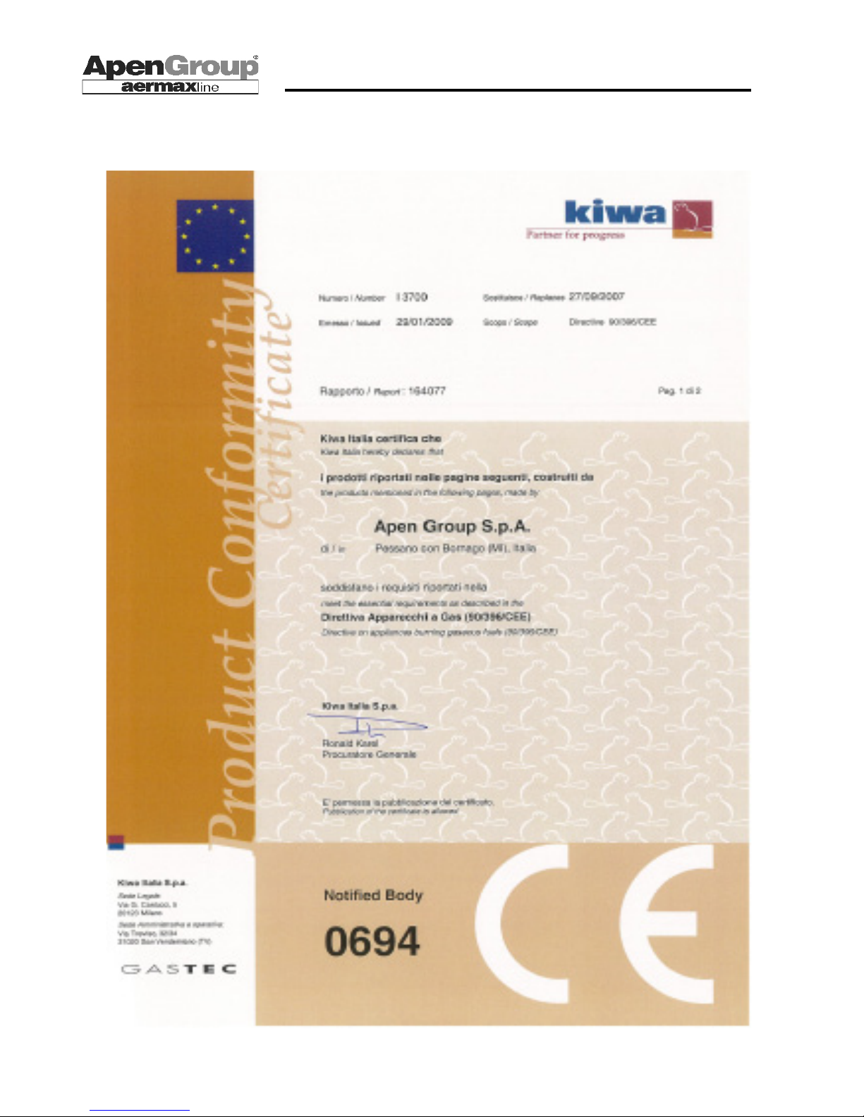
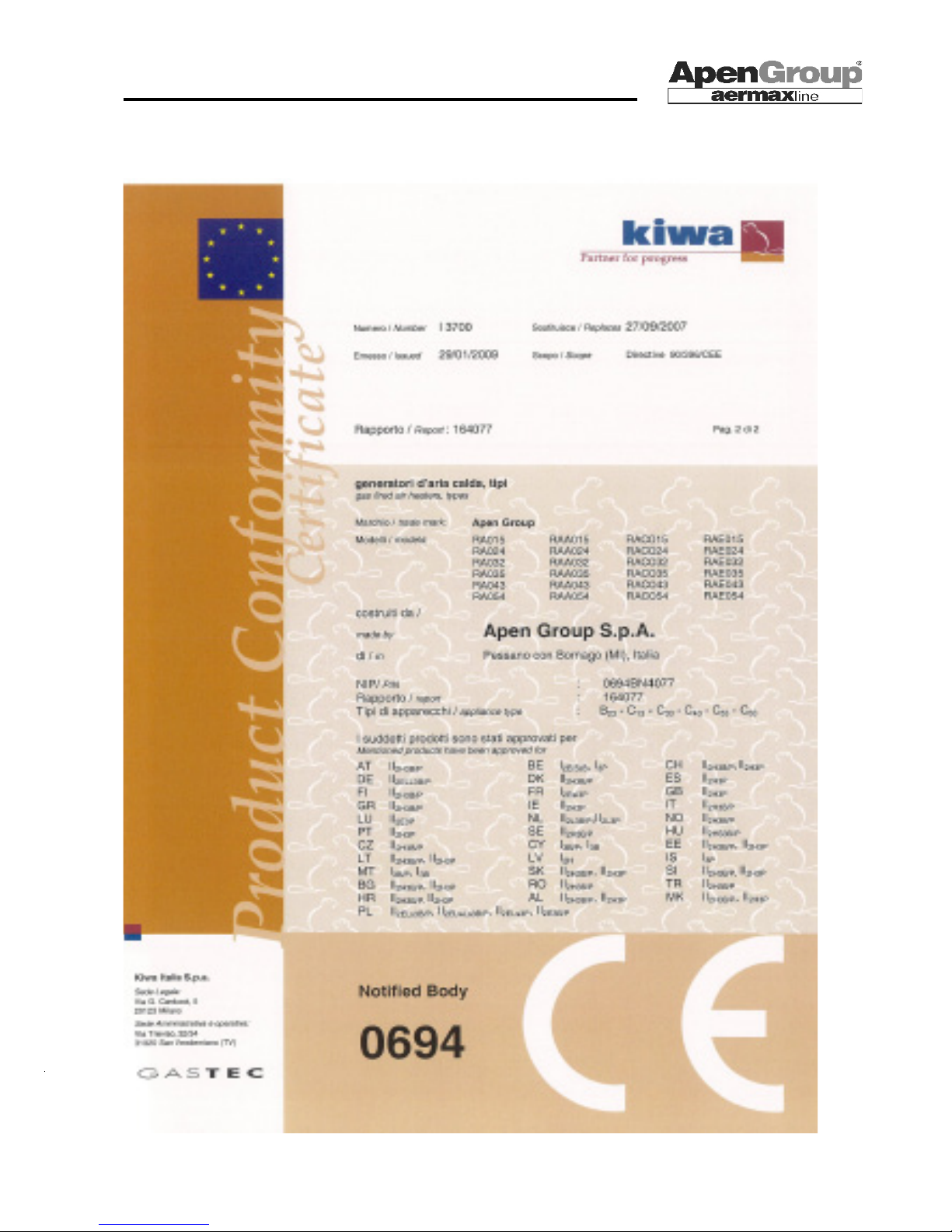
9. APPROVAL CERTIFICATE
Page 35
Page 35
APEN GROUP reserves the right to change products and documents as required.
code HG0109.12GB ed.C-1106 rev.12
WARM AIR HEATER SERIES RAPID
Page 36
Page 36
code HG0109.12GB ed.C-1106 rev.12
APEN GROUP reserves the right to change products and documents as required.
WARM AIR HEATER SERIES RAPID
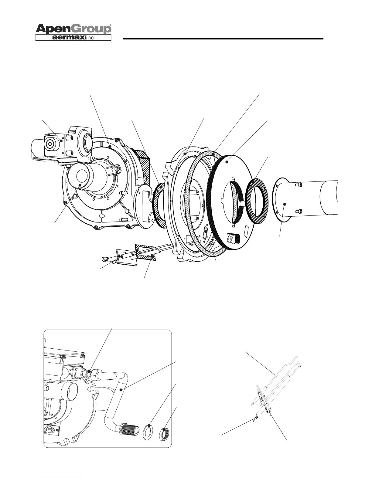
10. SPARE PART LIST - EXPLODED DRAWINGS
HG0107.08_C2_021
GAS TUBE SEAL
Code Model
C03430 (015/054)
GAS PIPE
Code Model
G14169.08 (015/054)
PANEL GASKET
Code Model
C00520 (015/054)
TUBE LOCKNUT
Code Model
X00630 (015/054)
GAS VALVE
Code Model
G12930 (015/054)
BURNER FAN
Model Code
G22803 (015/054)
BURNER FLANGE
GASKET
Code Model
G16332 (015/054)
BURNER GASKET
Code Model
G14086 (015/054)
BURNER HEAD
Code Model
G14534-P (015/024)
G14375.01-P (032/035)
G16340.01-P (043)
G14370.01-P (054)
Ø 8 GASKET
Code Model
G02285 (015/054)
FLANGE FUSION
Code Model
G16160 15/054)
FAN GASKET
Code Model
G14086 (015/054)
AIR/GAS VENTURI
Code Model
G14898 (015)
G14899 (024)
G14068 (032/035)
G14154 (043/054)
START-UP GROUP
WITH ELECTRODES
Code Model
G15020.02 (015/054)
GASKET
Code Model
G16331 (015/054)
PEEPHOLE GASKET
Code Model
G16329 (015/054)
PEEPHOLE GLASS
Code Model
G16324 (015/054)
PEEPHOLE FLANGE
Code Model
G16328 (015/054)
START-UP ELECTRODE
CODE MODEL
G16347 (015/054)
DETECTION ELECTRODE
Code Model
G16334 (015/054)
HG0109.08_C2_008
GASKET
CODE MODEL
X01257 (015/054)
Page 37
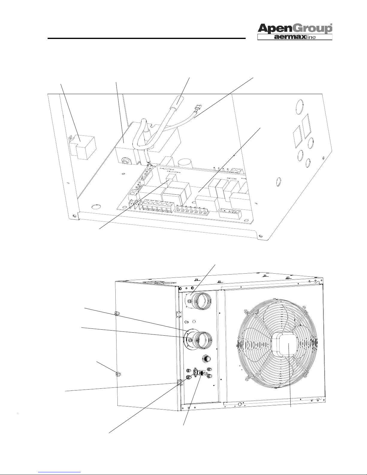
Page 37
APEN GROUP reserves the right to change products and documents as required.
code HG0109.12GB ed.C-1106 rev.12
WARM AIR HEATER SERIES RAPID
FLUE TERMINAL
Code Model
G14161.08 (015/054)
DETECTION WIRE
Code Model
G14993 (015/054)
START-UP
TRANSFORMER
Code Model
G12905.01 (015/054)
START-UP WIRE
Code Model
G14994 (015/054)
FLAME CONTROL
DEVICE
Code Model
G04600 (015/054)
FUSE - 6.3A - ST
Code Model
X00519 (015/035)
CLOSING HANDLE
Code Model
G14531 (015/054)
GASKET Ø 80
Code Model
G04378 (015/054)
REMOVABLE PLUG
Code Model
G12063 (015/054)
HG0109.09_C2_007
AIR TERMINAL
Code Model
G01239 (015/054)
HINGE
Code Model
X00536 (015/054)
FIXED PLUG
Code Model
G12064.01 (015/054)
MODEL Fan
RA015 C09250 Hidria #1
RA024/32 G03270 Hidria #1
RA035 G14890 Hidria #1
RA043 G03270 Hidria #1
RA054 G14890 Hidria #2
THERMOSTAT (STB)
Code Model
G16300 1X RA015/032
2X RA043/054
Page 38
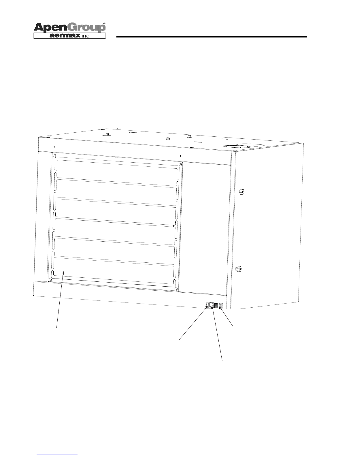
Page 38
code HG0109.12GB ed.C-1106 rev.12
APEN GROUP reserves the right to change products and documents as required.
WARM AIR HEATER SERIES RAPID
HORIZONTAL LOUVER
Code Model
G15213 -S (015)
G15313 -S (024/032/035)
G15333 -S (043)
G15353 -S (054)
HG0109.12_C2_015.pdf
LEDs
Code Model
G14992.01 015/054) Red
G14991.01 (015/054) Green
SUMMER/0 /WINTER SWITCH
Code MODEL
G12209.01 (015/054)
RESET BUTTON
Code MODEL
G13268 (015/054)
Page 39
Page 39
APEN GROUP reserves the right to change products and documents as required.
code HG0109.12GB ed.C-1106 rev.12
WARM AIR HEATER SERIES RAPID
Note
_________________________________________________________________________________________
_________________________________________________________________________________________
_________________________________________________________________________________________
_________________________________________________________________________________________
_________________________________________________________________________________________
_________________________________________________________________________________________
_________________________________________________________________________________________
_________________________________________________________________________________________
_________________________________________________________________________________________
_________________________________________________________________________________________
_________________________________________________________________________________________
_________________________________________________________________________________________
_________________________________________________________________________________________
_________________________________________________________________________________________
_________________________________________________________________________________________
_________________________________________________________________________________________
_________________________________________________________________________________________
_________________________________________________________________________________________
_________________________________________________________________________________________
_________________________________________________________________________________________
_________________________________________________________________________________________
_________________________________________________________________________________________
_________________________________________________________________________________________
_________________________________________________________________________________________
Page 40

Page 40
code HG0109.12GB ed.C-1106 rev.12
APEN GROUP reserves the right to change products and documents as required.
WARM AIR HEATER SERIES RAPID
APEN GROUP S.p.A.
Capitale sociale E 928.800 interamente versato
20060 Pessano con Bornago - Milan
Via Isonzo, 1 - Tel. +39 2 9596931
Fax +39 2 95742758
Website: http://www.apengroup.com
E-mail: [email protected]
Tax Registration Number 08767740155
 Loading...