

Page 1
Page 2

WELCOME
to Mobility Lab
Using APDM’s advanced wearable sensors, Mobility Lab makes it easy to collect,
analyze, and store outcome measures. Attach sensors to your subject, and instruct
them to perform a standardized test. A report is then automatically generated to
compare against normative values.
web: www.apdm.com
email: [email protected]
phone: 888-988-APDM (2736)
Page 3
CONTENTS
Hardware Cong
Setup M.L. How to
Hardware Cong
Hardware Cong
Parts
Setup M.L. How to
Hardware Cong
PARTS
SETUP
1
7
SOFTWARE INSTALLATION
USING YOUR SOFTWARE
11
9
TIPS
23
TROUBLESHOOTING
INFORMATION
29
25
Page 4

PARTS
Setup M.L. How to
M.L. Software Download Troubleshooting
Hardware Cong
Page 5
OPALS
Hardware Cong
Setup M.L. How to
Hardware Cong
Hardware Cong
Parts
Setup M.L. How to
Hardware Cong
DOCKING STATION
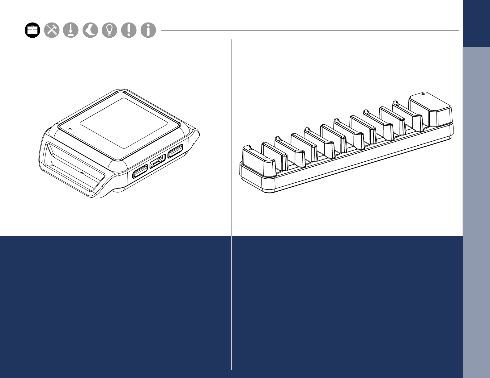
The Opal movement sensors precisely record
movement with triaxial accelerometers,
gyroscopes, and magnetometers.
The Docking Station is used to charge and
congure the Opal movement sensors.
2
Page 6
ACCESS POINT
Hardware Cong
Setup M.L. How to
Hardware Cong
Hardware Cong
Parts
Setup M.L. How to
Hardware Cong
WIRELESS REMOTE
3
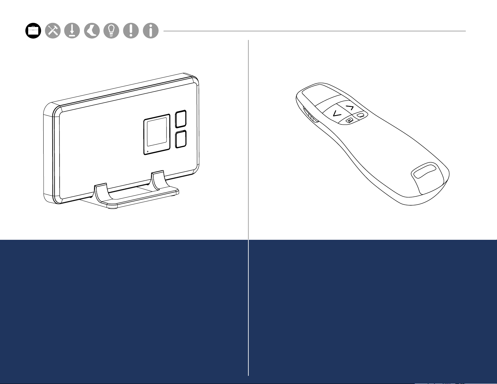
The wireless Access Control Point allows for
wireless communication between the host
computer and Opal movement sensors. A single
Access Point can support up to 6 Opals.
The Mobility Lab software supports the use of
a remote control to aid while collecting data.
This functionality makes it possible for a single
attendant to collect data while following or
assisting the subject.
Page 7
FOOTPLATE
Hardware Cong
Setup M.L. How to
Hardware Cong
Hardware Cong
Parts
Setup M.L. How to
Hardware Cong
USB DRIVE
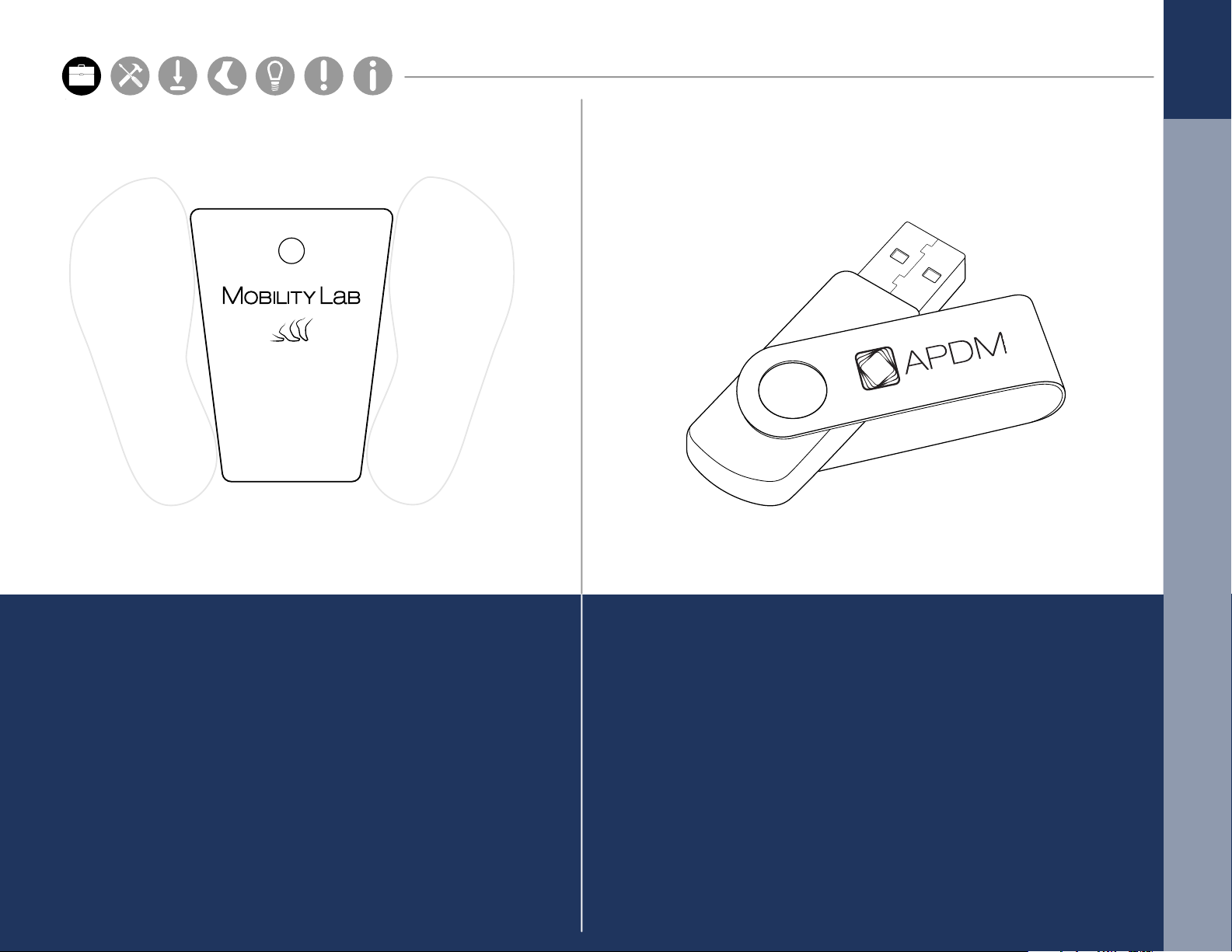
The Mobility Lab Footplate is designed to
standardize stance width before each Mobility
Lab test, unless otherwise noted.
The USB drive contains the Mobility Lab
software for automated analysis and reporting.
4
Page 8
A
Hardware Cong
Setup M.L. How to
Hardware Cong
Hardware Cong
Parts
Setup M.L. How to
Hardware Cong
B C
5
STRAPS
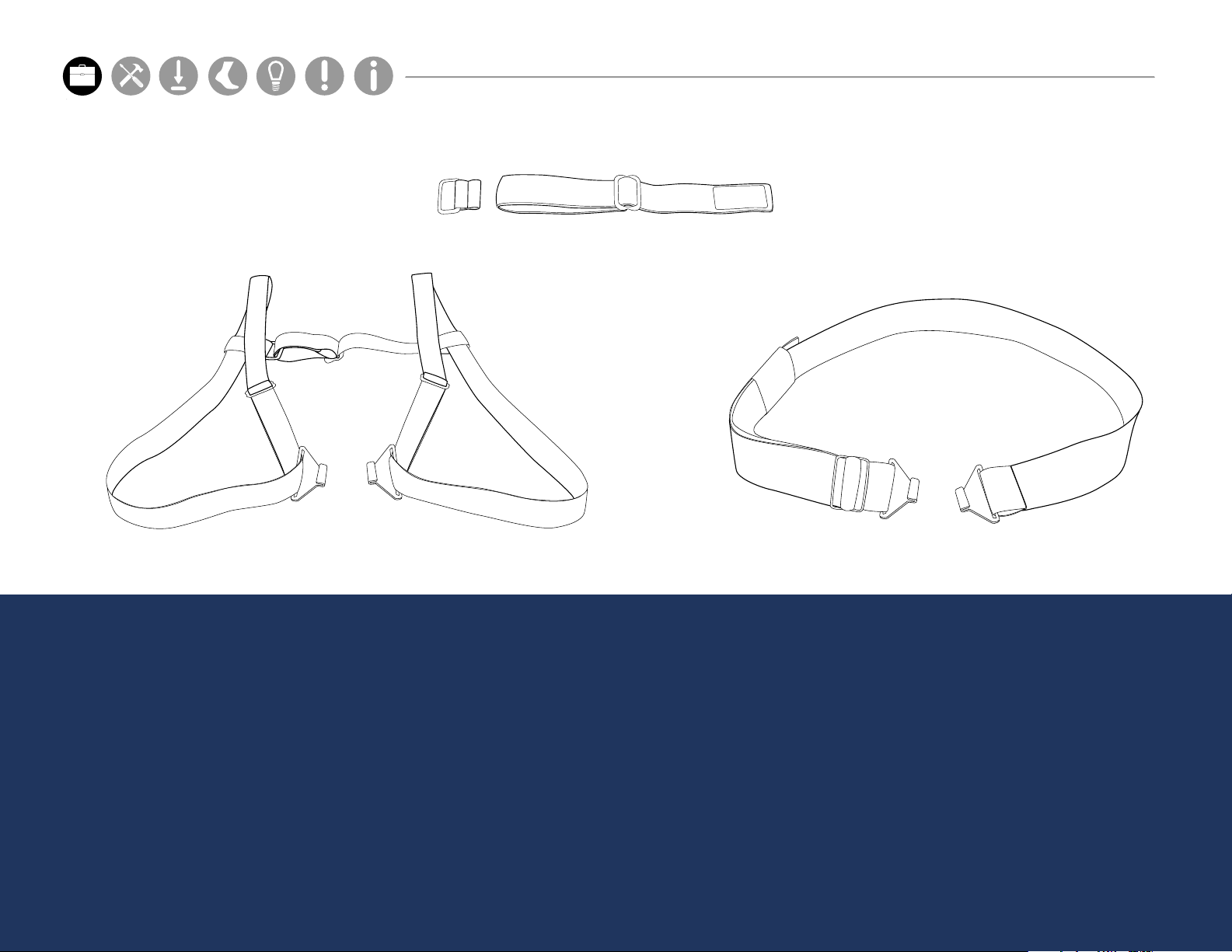
There are a number of options for securing the
sensors on subjects using a selection of straps.*
*All straps are latex-free.
A. Wrist and Foot strap
B. Sternum strap
C. Lumbar strap
Page 9
Hardware Cong
Setup M.L. How to
Hardware Cong
Hardware Cong
Parts
Setup M.L. How to
Hardware Cong
Sensor Placement
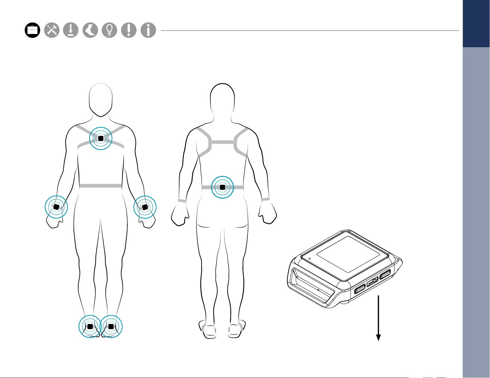
Your Mobility Lab system comes with all or some of the sensors shown.
To upgrade your system, contact us at 888-988-APDM (2736) or [email protected].
Always place
the Opal port
side down
6
Page 10

SETUP
Setup M.L. How to
M.L. Software Download Troubleshooting
Hardware Cong
Page 11
SETUP
Hardware Cong
Setup M.L. How to
Hardware Cong
Hardware Cong
Parts
Setup M.L. How to
Hardware Cong
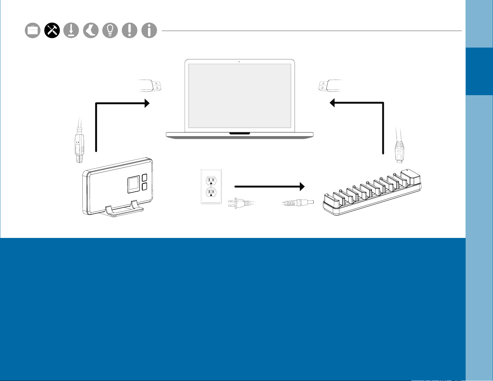
1. Connect the Access Point to your computer using the Type-B USB cable provided.
2. Connect the external power adapter to the Docking Station, and plug it in.
3. Connect the Docking Station to your computer using the Micro USB cable provided.
4. Plug the Opal(s) into the Docking Station.
It is the responsibility of the user to use the needed accessories supplied with the
equipment. Changes or modications not expressly approved by APDM could void
user authority to operate the equipment.
8
Page 12
SOFTWARE
INSTALLATION
Page 13
Requirements
Hardware Cong
Setup M.L. How to
Hardware Cong
Hardware Cong
Parts
Setup M.L. How to
Hardware Cong
Operating System
Windows 7 (64-bit) or later.
Installation
(Make sure you have Internet Explorer 10 or later installed.)
OSX Mountain Lion or later.
RAM
4GB+
Processor
Intel Core i3 or better.
Recommended Intel Core i5 or i7.
Drive Space
500MB for installation.
Recommended 100GB+ for ample
recording storage.
Macintosh OSX
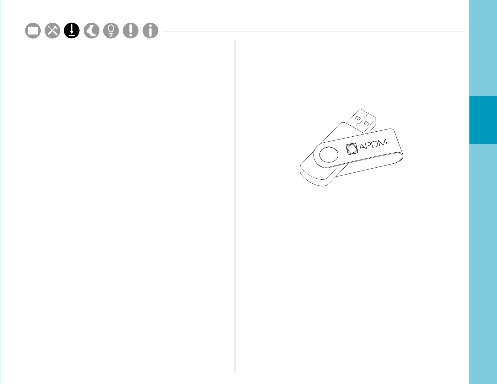
• Insert the provided USB drive into your computer.
Drag the Mobility Lab icon into the Applications
folder to install.
Windows
• Insert the provided USB drive into your computer.
Double click on the setup le. This will guide you
through the installation process.
10
Page 14

USING YOUR
SOFTWARE
M.L. Software Download Troubleshooting
Hardware Cong
Page 15
1
Hardware Cong
Setup M.L. How to
Hardware Cong
Hardware Cong
Parts
Setup M.L. How to
Hardware Cong
2
3
4
5
Subject Group
MENU
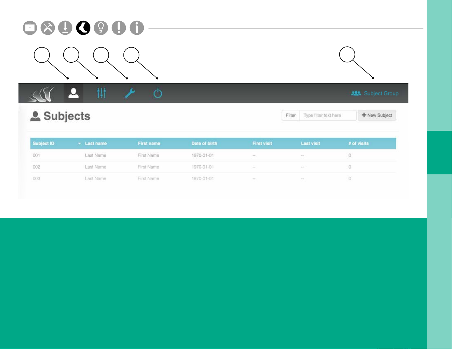
1. Subjects
The Subjects tab shows all of the subjects in your
Mobility Lab system for a selected subject group.
2. Options
The Options tab shows all of the display options
in your Mobility Lab system for a selected
subject group.
3. Hardware Conguration
The Hardware Conguration tab shows assigned
sensor locations on the body.
4. Power O Sensors
The Power O Sensors tab turns o any docked
sensors for storage.
5. Subject Group Selection
The Subject Group Selection dropdown allows
you to select, add, edit, delete, and export data
for a specic subject group.
12
Page 16
SUBJECTS
Hardware Cong
Setup M.L. How to
Hardware Cong
Hardware Cong
Parts
Setup M.L. How to
Hardware Cong
13
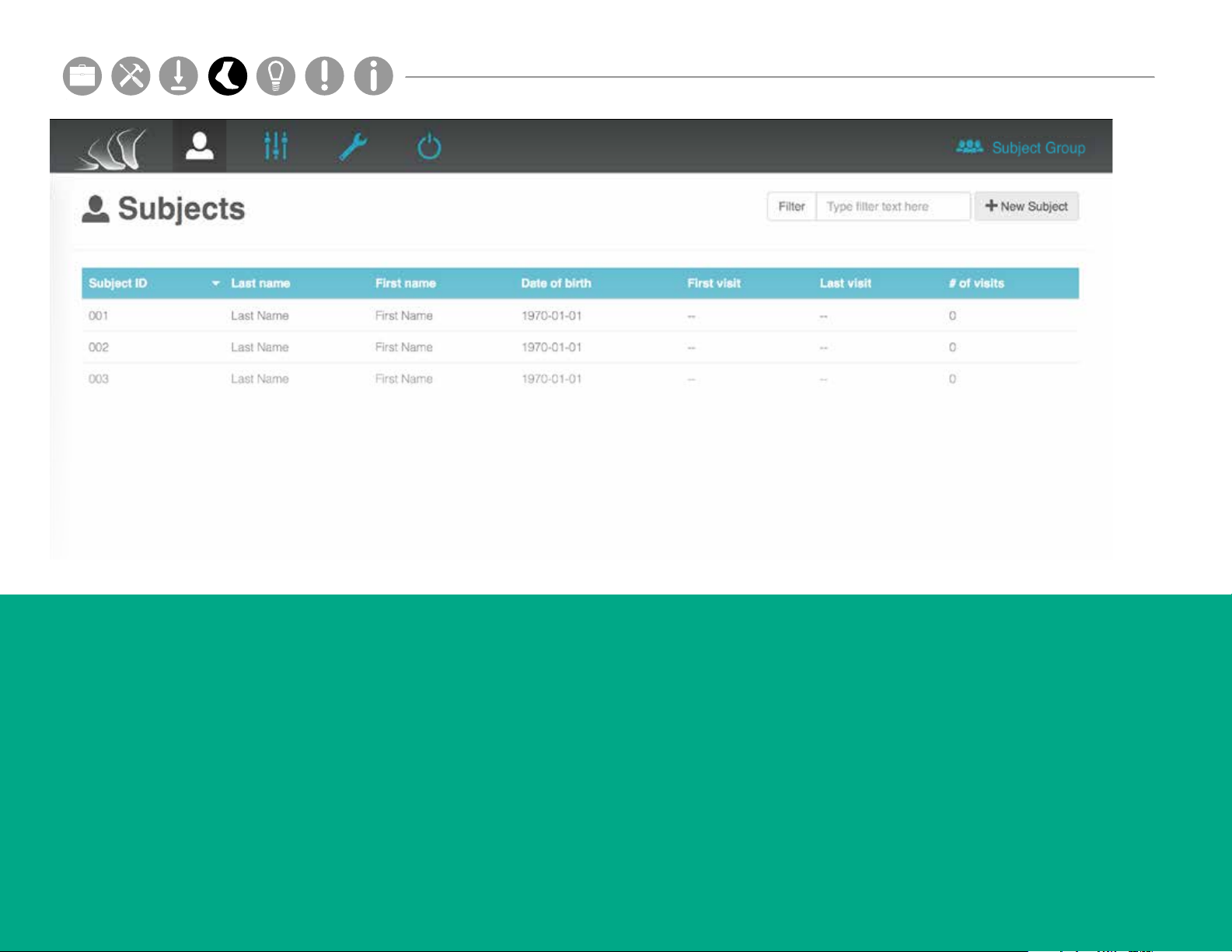
The Subjects tab shows all of the test subjects in
your Mobility Lab system for a selected subject
group.
Adding a Subject
Click on the “New Subject” button on the top
right of your screen. Fill in the required elds
and click Save.
Running a Test
Click on the subject you wish to test. Click on the “New
Test” button on the top right of your screen.
Finishing a Test Sequence
Click on the subject you wish to test. Click on the
red “bell” icon to the right of an unnished test
sequence. This option will be active for 24 hours after
the sequence is started.
Page 17
M.L. Software Download Troubleshooting
Hardware Cong
Hardware Cong
Setup M.L. How to
Hardware Cong
Hardware Cong
Parts
Setup M.L. How to
Hardware Cong
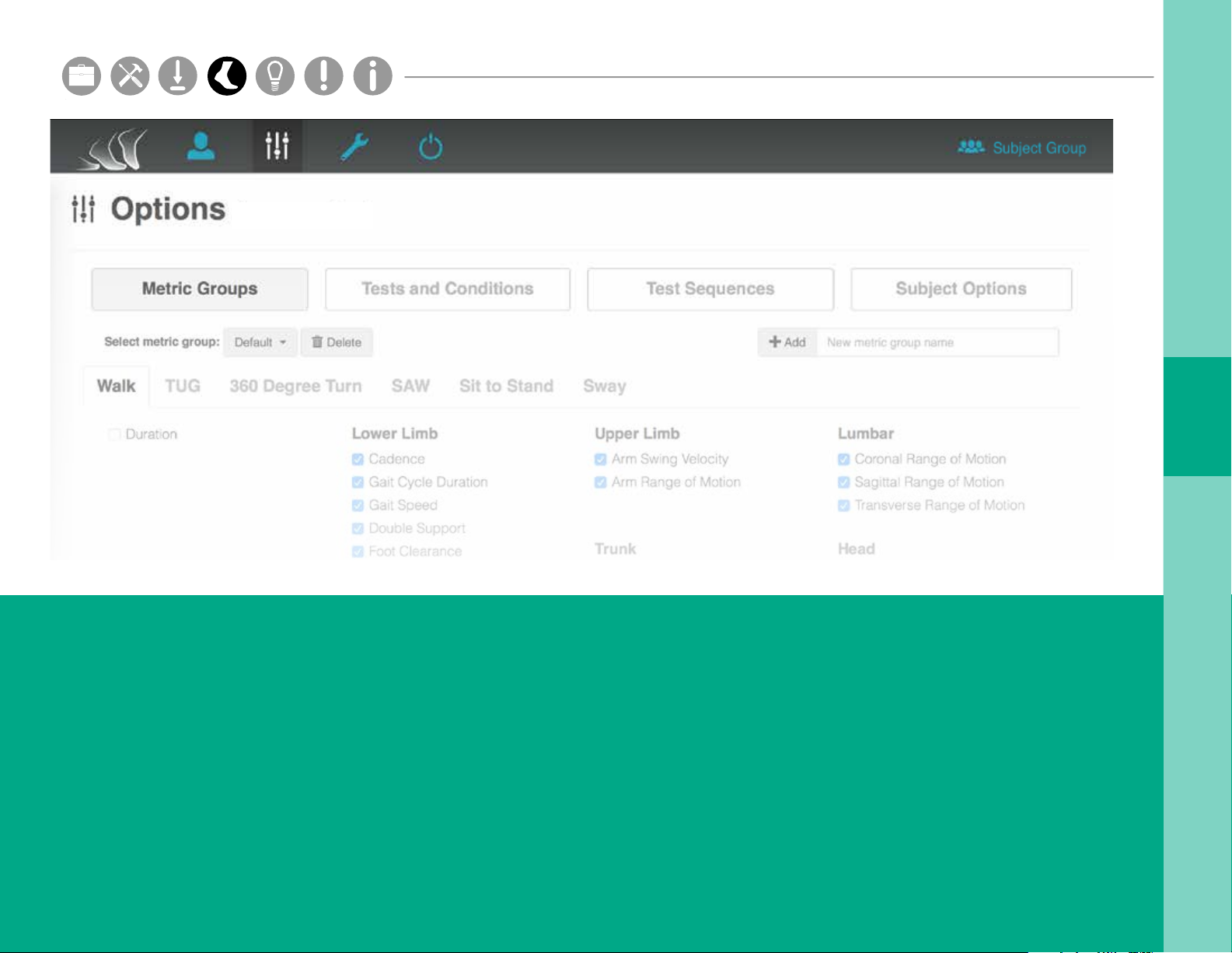
OPTIONS
The Options tab shows all of the display options
in your Mobility Lab system for a selected subject
group.
Metric Groups
The “Metric Groups” page allows you to
change which metrics are displayed in the
test results window, and add custom metric
groups for each test.
Tests and Conditions
The “Tests and Conditions” page allows you to
add, edit, and delete custom tests and test conditions*.
Test Sequences
The “Test Sequences” page allows you to add, edit,
and delete custom test sequences.
Subject Options
The “Subject Options” page allows you to select the
required and displayed elds on the subjects tab.
* Added feature
14
Page 18
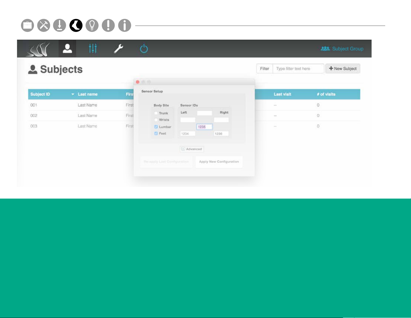
HARDWARE CONFIGURATION
Hardware Cong
Setup M.L. How to
Hardware Cong
Hardware Cong
Parts
Setup M.L. How to
Hardware Cong
15
The Hardware Conguration tab shows assigned sensor
locations on the body.
Body Site
Check the boxes next to the body sites you
wish to record from.
Sensor IDs
For each body site you record from, you must specify
the ID of the Opal you will place on that location. The
sensor ID is etched on the back of each Opal.
Advanced
Click here for Custom Sensor Location Setup,
Recording Options, and Wireless Remote settings.
Apply New Conguration
Click here when you are done choosing your
conguration options.
Video, External Synchronization, and Continuous
Monitoring settings can be accessed in the Tools
dropdown of the menu bar.
* Added feature
Page 19
Hardware Cong
Setup M.L. How to
Hardware Cong
Hardware Cong
Parts
Setup M.L. How to
Hardware Cong
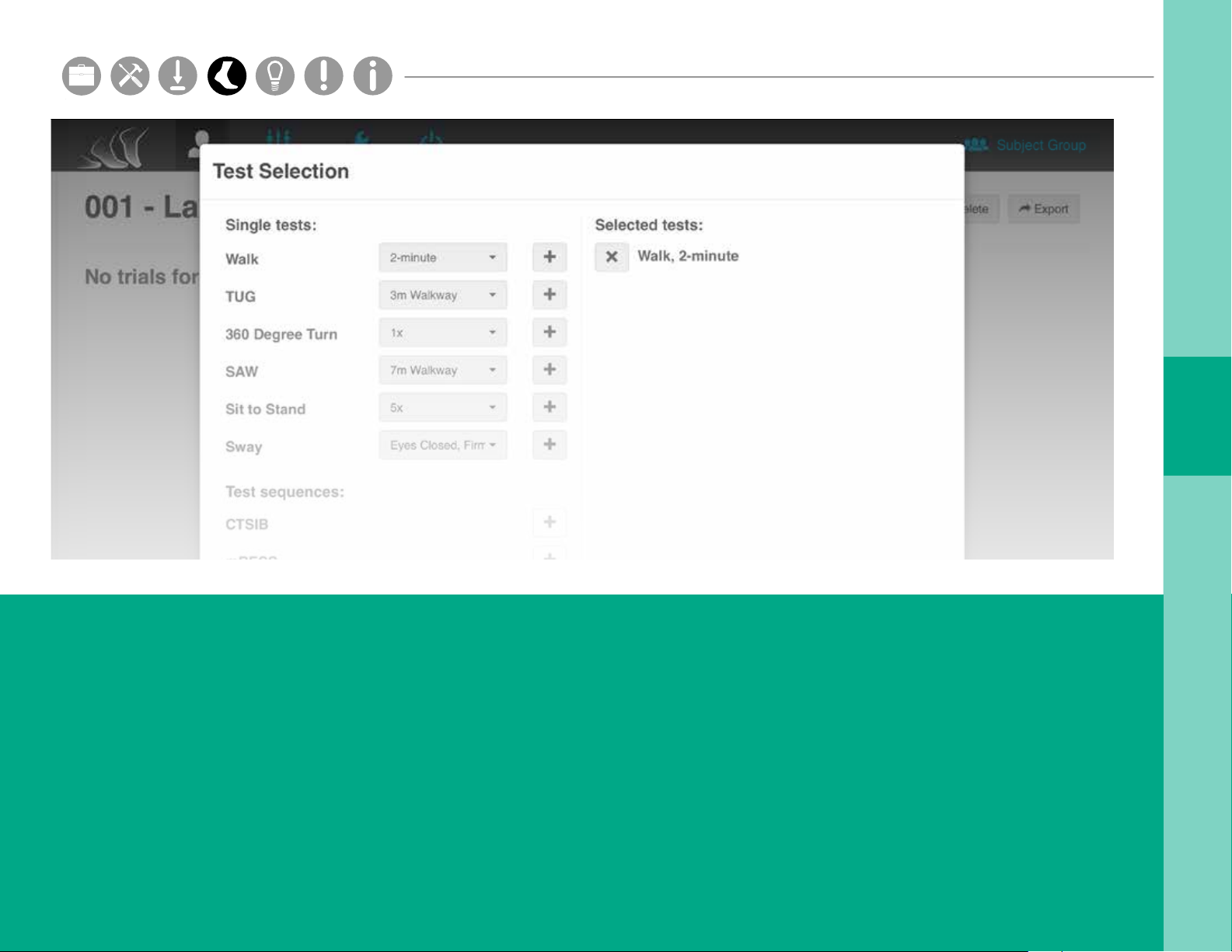
RUNNING A TEST
1. Click on the subject you wish to test. Click on the
“New Test” button on the top right of your
screen, and select the test(s) you wish to run.
2. Select the test(s) and condition(s) you would
like to run. You may select multiple tests or one
test sequence. Click Next to continue.
3. Make sure the necessary sensors are undocked and
attached to the subject on the proper body sites.
Click Next to continue.
4. Follow the instructions on each dialogue box to
complete each test.
5. If using the wireless remote, press the forward
button to start and stop each test.
16
Page 20
Hardware Cong
Setup M.L. How to
Hardware Cong
Hardware Cong
Parts
Setup M.L. How to
Hardware Cong
1 3
2
4
17
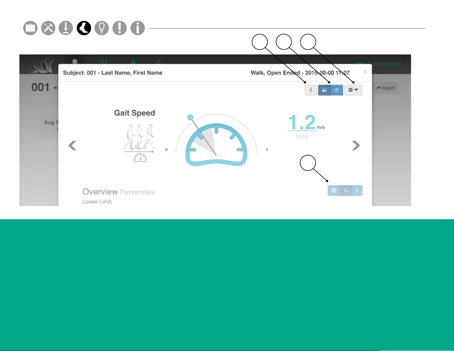
TEST RESULTS WINDOW
3. Tools Dropdown
1. Information Key
The Information Key shows denitions for each
metric, and information on how to read each
graph.
2. Visualization Options
The Visualization Options show the data graph
in dierent formats for a selected test.
The Tools Dropdown allows you to edit
displayed metrics, access print view, export and
upload trial data*, and delete a test.
4. Overview Options
The Overview Options show the data table in
dierent formats for a selected test.
Norms are collected progressively from third party
institutions. For more information, visit support.apdm.com.
* Added feature
Page 21
Test s
TESTS
Walk
TESTS
W
Walk
TUG
TESTS
W
T
Walk
TUG
Sway
TESTS
W
S
T
Walk
TUG
Sway
CTSIB
mBESS
TESTS
W
S
C
T
Walk
TUG
Sway
CTSIB
mBESS
360º Turn
TESTS
W
S
mB
C
T
Walk
TUG
Sway
CTSIB
mBESS
360º Turn
Sit to Stand
TESTS
W
S
mB
C
T
360
Walk
TUG
Sway
CTSIB
mBESS
360º Turn
Sit to Stand
TESTS
W
S
mB
C
T
sS
360
Walk
TUG
Sway
CTSIB
mBESS
360º Turn
Sit to Stand
TESTS
W
S
mB
C
T
sS
360
SAW
Sw
Hardware Cong
Setup M.L. How to
Hardware Cong
Hardware Cong
Parts
Setup M.L. How to
Hardware Cong
Opals
Test Measures
Full body gait (legs, arms, and trunk), Asymmetry, Variability and Turning
Postural transitions (sit, stand, and turning)
Postural sway
Postural sway, Visual dependence, Proprioceptive dependence, and Vestibular loss
Postural stability in varying conditions
Turn velocity, Turn time, Number of steps
Trunk excursion, Stand time, Cadence, Total time
3+
3+
1+
1+
1+
3+
3+
Full body gait (legs, arms, and trunk), Asymmetry, Variability, Turning, and Postural Stability
3+
W
T
360
C
mB
S
sS
Sw
W
Walk
T
TUG
S
Sway
C
CTSIB
mB
360
sS
Sw
SAW
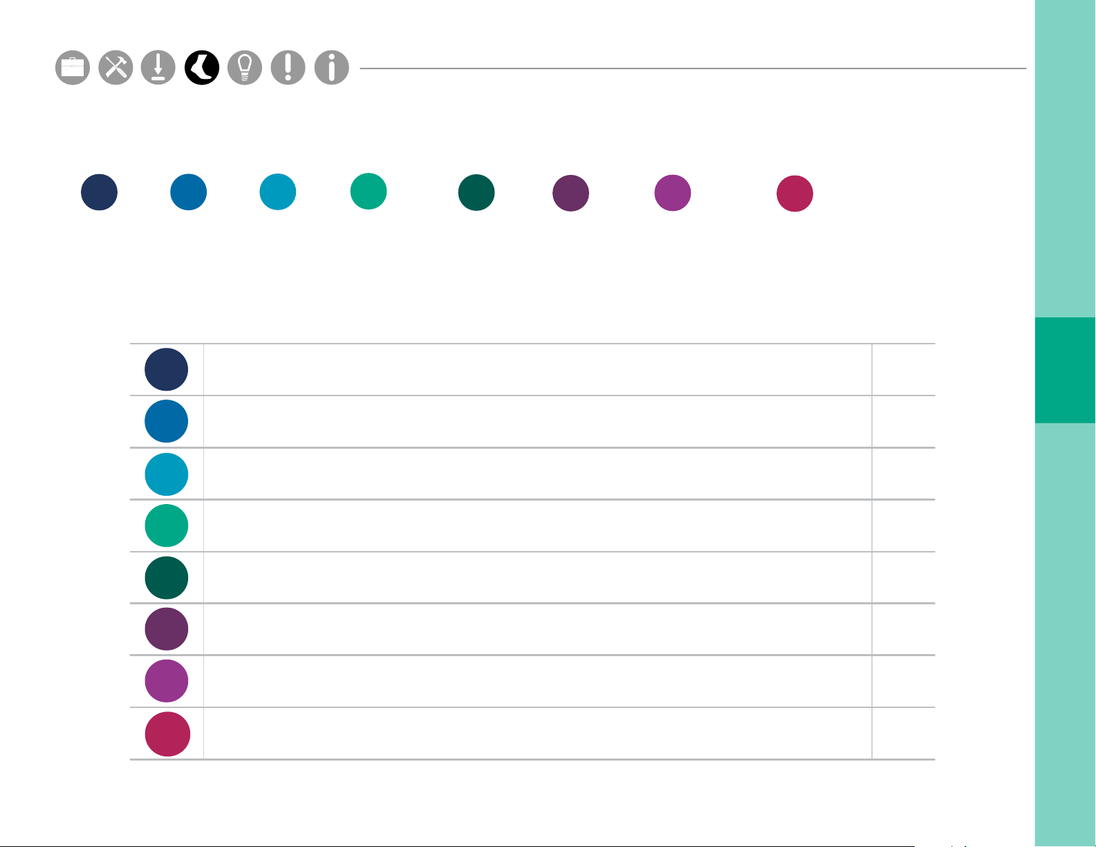
The Mobility Lab system comes equipped with multiple tests. The table below indicates what each test can
measure, and how many Opal sensors are necessary to run each test.
18
Page 22
Hardware Cong
Setup M.L. How to
Hardware Cong
Hardware Cong
Parts
Setup M.L. How to
Hardware Cong
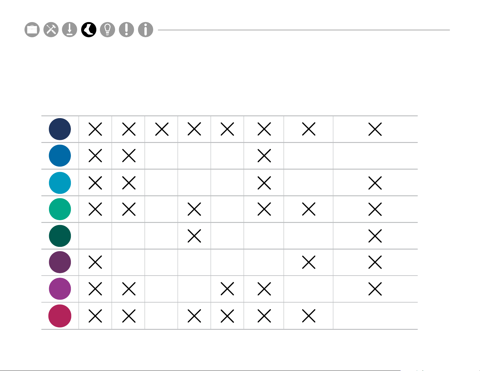
Each test within the Mobility Lab system is designed to capture data that may help improve the analysis of certain
TESTS
mobility and balance issues. The table below suggests which tests can be helpful to capture this data.
PD MS CP TBI Stroke Dementia Vestibular DisordersFall Risk
W
T
S
C
mB
19
360
sS
Sw
Page 23
Hardware Cong
Setup M.L. How to
Hardware Cong
Hardware Cong
Parts
Setup M.L. How to
Hardware Cong
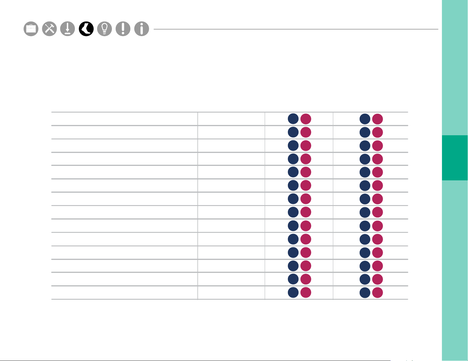
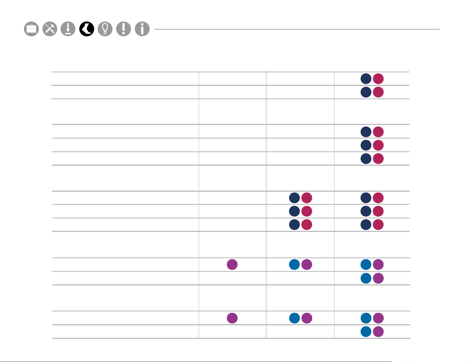
Each test within the Mobility Lab system is designed to capture data for certain metrics. The table below indicates
Tier 1
Tier 2
Tier 3
Lower Limb
the metrics that each test captures, and how many Opal sensors are necessary to gather data for each metric.
Cadence
Gait Cycle Duration
Gait Speed
Elevation at Midswing
Double Support
Lateral Step Variability
Circumduction
Foot Strike Angle
Toe O Angle
Stance
Step Duration
Stride Length
1 Opal sensor
3 Opal sensors
W
W
W
W
W
W
W
W
W
W
W
W
Sw
Sw
Sw
Sw
Sw
Sw
Sw
Sw
Sw
Sw
Sw
Sw
6 Opal sensors
W
W
W
W
W
W
W
W
W
W
W
W
Sw
Sw
Sw
Sw
Sw
Sw
Sw
Sw
Sw
Sw
Sw
Sw
Swing
Toe Out Angle
W
W
Sw
Sw
W
W
Sw
Sw
20
Page 24
Stance
Step Duration
Stride Length
Swing
Toe Out Angle
Sw
Sw
Sw
Sw
Sw
W
W
W
W
W
Upper Limb
Sw
Sw
Sw
Sw
Sw
W
W
W
W
W
Tier 1
1 Opal sensor
Tier 2
3 Opal sensors
Tier 3
6 Opal sensors
Lower Limb
Cadence
Gait Cycle Duration
Gait Speed
Elevation at Midswing
Double Support
Lateral Step Variability
Circumduction
Foot Strike Angle
Toe O Angle
Stance
Step Duration
Stride Length
Swing
Toe Out Angle
W
Sw
Sw
Sw
Sw
Sw
Sw
Sw
Sw
Sw
Sw
Sw
Sw
Sw
Sw
W
W
W
W
W
W
W
W
W
W
W
W
W
W
Sw
Sw
Sw
Sw
Sw
Sw
Sw
Sw
Sw
Sw
Sw
Sw
Sw
Sw
W
W
W
W
W
W
W
W
W
W
W
W
W
Hardware Cong
Setup M.L. How to
Hardware Cong
Hardware Cong
Parts
Setup M.L. How to
Hardware Cong
Upper Limb
Maximum Velocity
Range of Motion
Trunk Range of Motion
Coronal
Sagittal
Transverse
Lumbar Range of Motion
1 Opal sensor 3 Opal sensors 6 Opal sensors
W
W
W
W
W
Sw
Sw
Sw
Sw
Sw
Coronal
Sagittal
Transverse
Sit To Stand
Duration
Lean Angle
Stand To Sit
21
Duration
Lean Angle
sS
W
W
W
T
T
Sw
Sw
Sw
sS
sSsS
W
W
W
T
T
T
T
Sw
Sw
Sw
sS
sS
sS
sS
Page 25
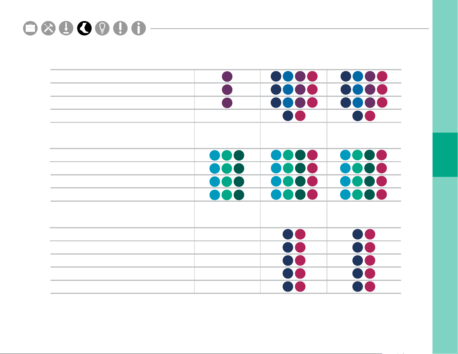
Turning
Sit To Stand
Duration
Lean Angle
Stand To Sit
Duration
Lean Angle
T
sS
T
sSsS
sS
T
sS
T
sS
T
sS
T
sS
Step Duration
Stride Length
Swing
Toe Out Angle
Lumbar Range of Motion
Coronal
Sagittal
Transverse
Trunk Range of Motion
Coronal
Sagittal
Transverse
Sw
Sw
Sw
Sw
Sw
Sw
Sw
W
W
W
W
W
W
W
Turning
Sit To Stand
Duration
Lean Angle
Stand To Sit
Duration
Lean Angle
Maximum Velocity
Range of Motion
Upper Limb
Sw
Sw
Sw
W
W
W
Sw
Sw
Sw
W
W
W
Sw
Sw
W
W
Sw
Sw
Sw
Sw
W
W
W
W
T
sS
T
sSsS
sS
T
sS
T
sS
T
sS
T
sS
Hardware Cong
Setup M.L. How to
Hardware Cong
Hardware Cong
Parts
Setup M.L. How to
Hardware Cong
Angle
Duration
Velocity
Steps in Turn
Postural Sway
95% Ellipse Sway Area
RMS Sway
Coronal RMS Sway
1 Opal sensor 3 Opal sensors 6 Opal sensors
360
360
360
C
S
C
S
C
S
mB
mB
mB
W
W
W
S
S
S
T
T
T
W
C
C
C
360
360
360
Sw
mB
mB
mB
Sw
Sw
Sw
Sw
Sw
Sw
W
W
W
S
S
S
T
T
T
W
C
C
C
360
360
360
Sw
mB
mB
mB
Sw
Sw
Sw
Sw
Sw
Sw
Anticipatory Postural Adjustment
mB
Sw
Sw
Sw
Sw
Sw
Sw
S
Sagittal RMS Sway
S
mB
C
Duration
First Step Duration
First Step Range of Motion
Sagittal Max Acceleration
Coronal Max Acceleration
To upgrade your APDM sensor system, contact us at 888-988-APDM (2736) or [email protected].
C
S
W
W
W
W
W
C
W
W
W
W
W
mB
Sw
Sw
Sw
Sw
Sw
Sw
22
Page 26

TIPS
Hardware Cong
Page 27

Storage
Hardware Cong
Setup M.L. How to
Hardware Cong
Hardware Cong
Parts
Setup M.L. How to
Hardware Cong
In most situations, it is sufficient to simply dock your sensors when not in use. When docked, sensors stop
recording, stop broadcasting, and charge batteries. Do not leave sensors docked in a docking station that is not
plugged into a power outlet.
For transport and storage, it is best to power off all system components. This can be done by docking the
sensors and clicking the “Power Off” button in the Mobility Lab menu. The sensors will power down the next time
they are undocked.
Cleaning
Clean the Opal sensors with a rubbing alcohol or other cleaning wipe. Do not use methyl alcohol, as it will cause
degradation of the plastic over time.
The sensors and other system components should not be submerged in any liquids or subjected to any high
temperatures.
The sensor straps can be removed and washed separately using mild soap and water.
Subject Attire
The subject should wear clothing that does not bind their movement in any significant way.
Walking shoes should be worn (i.e. no heels or flip-flops).
24
Page 28
TROUBLESHOOTING
APDM is pleased to assist you with any questions you may have about your
hardware, software, or the use of the technology for your application.
Please contact us at:
web: support.apdm.com
email: [email protected]
Page 29
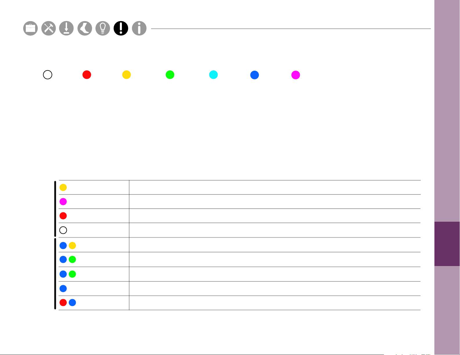
LED Colors
Hardware Cong
Setup M.L. How to
Hardware Cong
Hardware Cong
Parts
Setup M.L. How to
Hardware Cong
White
Red Yellow
Green
Cyan Blue Magenta
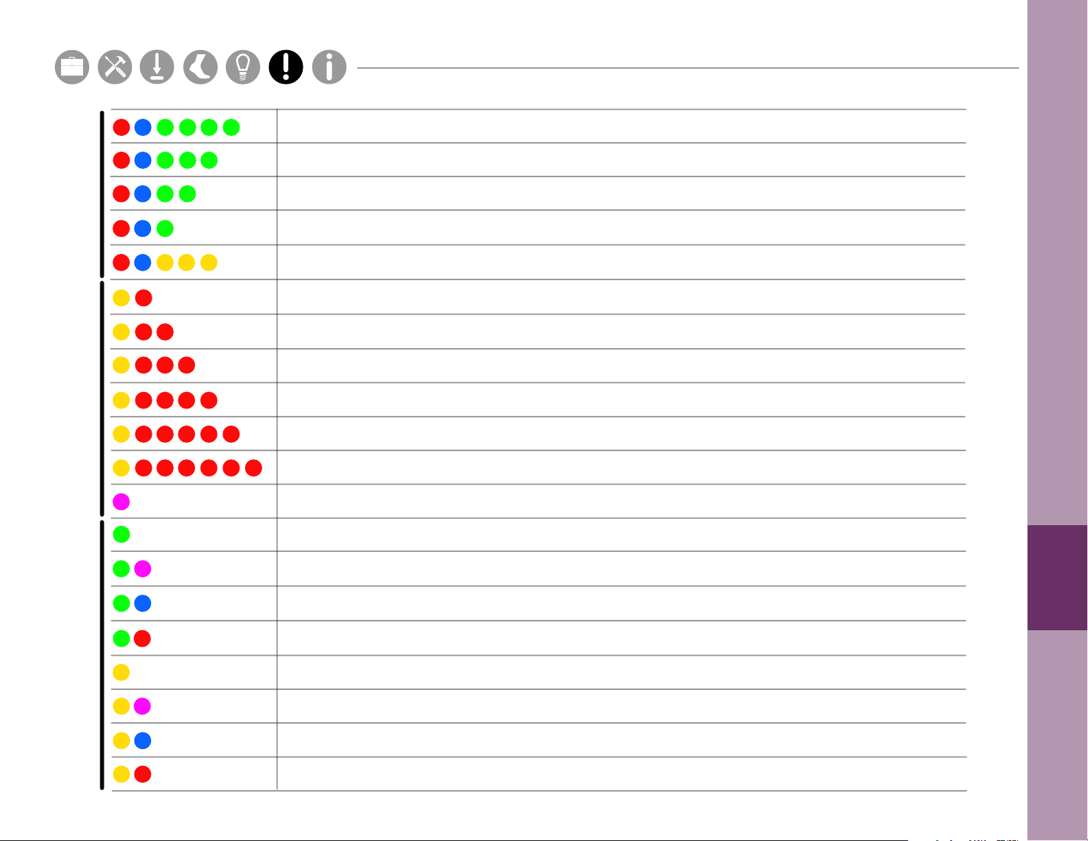
LED Patterns and Error Messages
The LED on the Access Point and sensors provides important information about the operating state of the
hardware. The table below lists the LED ashing patterns associated with these states, which can be useful in
troubleshooting issues encountered with the hardware.
State
Startup ModeFirmware Mode
Pattern
Startup wait (5 sec) v1.0, bootloader v1
Startup wait (5 sec) v1.1, bootloader v2
Failed to load rmware
Bootloader Mode
fast
slow
Docked Mode (pre-charging - very low battery)
Docked Mode (bulk charging - low battery)
Docked Mode (trickle charging - 80-100% charge)
Docked Mode (full charge)
Docked Mode (battery error)
26
Page 30
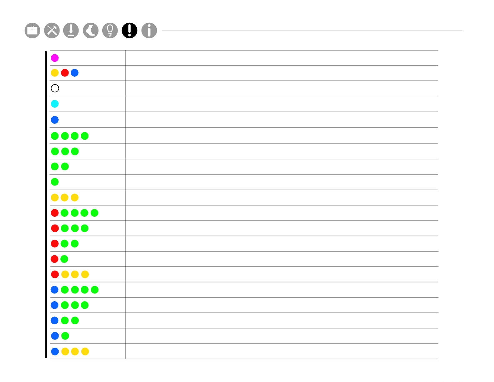
Docked Mode (wait)
Hardware Cong
Setup M.L. How to
Hardware Cong
Hardware Cong
Parts
Setup M.L. How to
Hardware Cong
Docked Mode (error)
Reset Mode
Transitioning into standby or powering o
Hold Mode
Run Mode (battery level 4, full)
Run Mode (battery level 3)
Run Mode (battery level 2)
Run Mode (battery level 1, low)
Run Mode (battery very low)
Run Mode (clock unset, battery level 4, full)
27
Firmware Mode
Run Mode (clock unset, battery level 3)
Run Mode (clock unset, battery level 2)
Run Mode (clock unset, battery level 1, low)
Run Mode (clock unset, battery very low)
Run Mode (no sync-lock, battery level 4, full)
Run Mode (no sync-lock, battery level 3)
Run Mode (no sync-lock, battery level 2)
Run Mode (no sync-lock, battery level 1, low)
Run Mode (no sync-lock, battery very low)
Page 31
Run Mode (clock unset, no sync-lock, battery level 4, full)
Hardware Cong
Setup M.L. How to
Hardware Cong
Hardware Cong
Parts
Setup M.L. How to
Hardware Cong
Run Mode (clock unset, no sync-lock, battery level 3)
Run Mode (clock unset, no sync-lock, battery level 2)
Run Mode (clock unset, no sync-lock, battery level 1, low)
Firmware ModeError ModeWireless Streaming Debug Mode
Run Mode (clock unset, no sync-lock, battery very low)
Error Mode (default)
Error Mode (conguration)
Error Mode (system)
Error Mode (data buer)
Error Mode (SD buer)
Error Mode (SD I/O)
Card is full
Normal
CPU limited
Sync bad
CPU limited, Sync bad
Missed sync > 0
Missed sync > 0, CPU limited
Missed sync > 0, Sync bad
Missed sync > 0, CPU limited, Sync bad
28
Page 32

INFORMATION
For complete sensor information, please visit www.apdm.com
Page 33
Hardware Cong
Setup M.L. How to
Hardware Cong
Hardware Cong
Parts
Setup M.L. How to
Hardware Cong
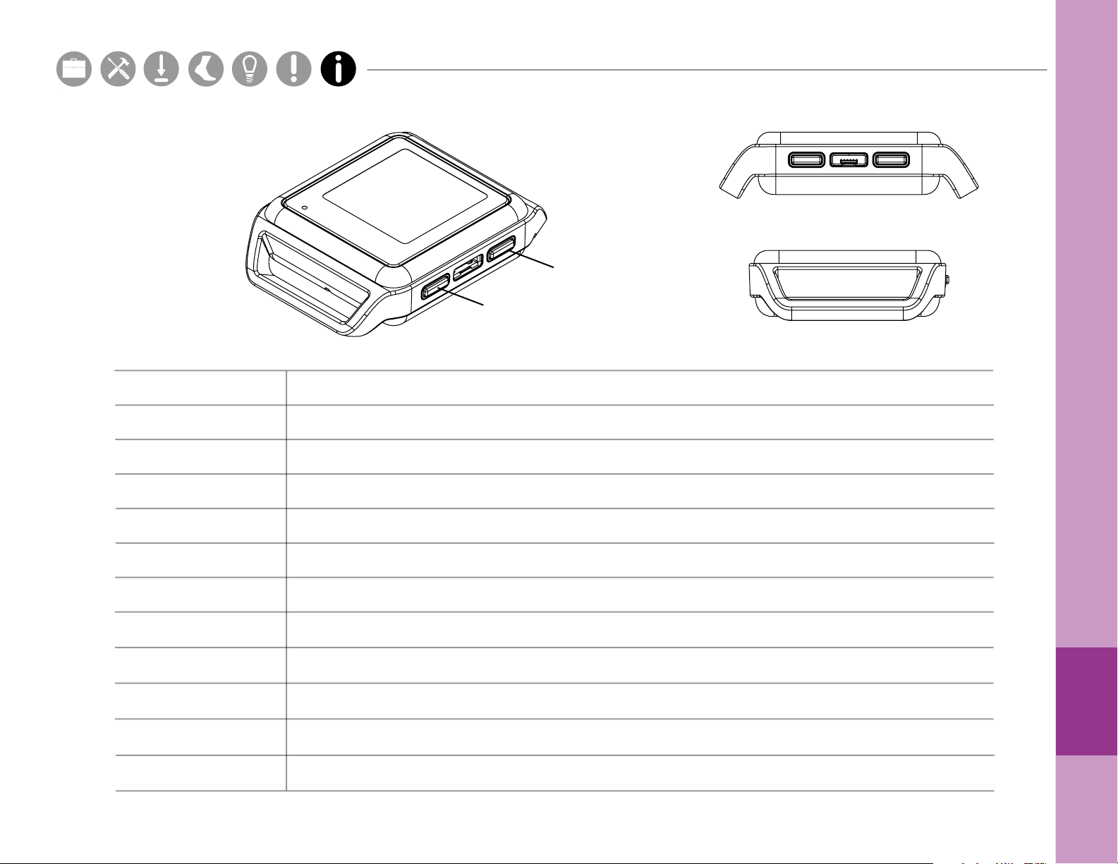
Button 2
Button 1
Dimensions
Material
Weight
Battery Life
Wireless Radio
Frequency Band
Data Rate
Latency
Transmission Range
Data Buer
Synchronization
Screen Resolution
55mm x 40.2mm x 12.5mm
PC-ABS plastic, glass
<25 grams (with battery)
Wireless Streaming (8h), Synchronous Logging (12h), Asynchronous Logging (16h)
Nordic Semiconductor nRF51822
2.40-2.48GHz ISM band, adjustable
2Mbps on-air data-rate
300ms (typical) with data buer, 30ms (typical) without data buer
30m line of sight, 10m indoors
8Gb (~720 hours)
_
<1ms dierence, up to 24 Opals
128px x 128px
30
Page 34
Compliance Information
FCC
This device complies with part 15 of the FCC Rules. Operation is subject to the following two conditions:
1. This device may not cause harmful interference.
2. This device must accept any interference received, including interference that may cause undesired operation.
Changes or modifications not expressly approved by APDM could void the user’s authority to operate the equipment.
To access FCC and IC information on the APDM Opal and Access Point - Press Button 2 twice from the home screen.
Industry Canada (IC)
This device complies with Industry Canada license-exempt RSS standard(s). Operation is subject to the following two conditions: (1) this device may not cause
interference, and (2) this device must accept any interference, including interference that may cause undesired operation of the device.
Le présent appareil est conforme aux CNR d’Industrie Canadienne applicables aux appareils radio exempts de licence. L’exploitation est autorisée aux deux
conditions suivantes : (1) l’appareil ne doit pas produire d’interférence, et (2) l’utilisateur de l’appareil doit accepter toute interférence subie, même si l’interférence
est susceptible d’en compromettre le fonctionnement.
WEEE Directive Statement for the European Union
In common with all Electronic and Electrical products, APDM equipment should not be disposed of in household waste. Alternative arrangements may apply in other
juristictions.
FCC ID: 2AHZD-OPAL
IC: 21349-OPAL
Model: Opal
FCC ID: 2AHZD-AP
IC: 21349-AP
Model: AP
Page 35

 Loading...