

Page 1
FOR INSTALLATION BY QUALIFIED SERVICE PERSONNEL ONLY
CONVERSION KIT INSTRUCTIONS
For Models CSB52** “I or S”, CSB82** “I or S” & CSB120** “I or S”
And Models (A)STCE31-50/80/119, (A)ITCE31-50/80/119
Commercial Electric Water Heaters
CAUTION
TEXT PRINTED OR OUTLINED IN RED CONTAINS
INFORMATION RELATIVE TO YOUR SAFETY.
PL E AS E R EA D TH O RO U GH LY BEF O RE
ATTEMPTING ANY CONVERSION.
PRINTED IN U.S.A. 1208 196679-002
125 Southeast Parkway
Franklin, TN 37068
1-800-433-2545
apcom-inc.com
1
Page 2

FOREWORD
The purpose of this manual is to explain how to change the voltage and wattage of your commercial electric water heater
by changing the elements. This manual is not intended to explain the rebuilding of commercial electric water heaters
in the eld.
Addition of heating elements or subtraction of heating elements in the eld is not approved by Underwriters Laboratories,
Inc., and therefore, is not allowed and should not be attempted.
Please note the limitation that “both the heater required and the heater to be converted must be found on the same
page” (in this manual) must be followed. Before attempting any conversion read the detailed instructions contained on
pages 8, 9, 10 and 11.
SAFETY
Be sure to disconnect appliance from electrical supply before working on or near the electrical system of the heater.
Never touch electrical components with wet hands or when standing in water.
REQUIRED ABILITY
CONVERSION OF ANY WATER HEATER LISTED IN THIS MANUAL REQUIRES ABILITY EQUIVALENT
TO THAT OF A LICENSED ELECTRICAL TRADESMAN.
TABLE OF CONTENTS
Foreword ............................................................... 2
Conversion Materials ............................................. 2
Conversion Guidelines ....................................... 3
Conversion Instructions
Introduction .......................................................... 4
Heater Preparation .............................................. 4
Page
KW Conversion (Element Replacement) ............. 4
Voltage Conversion ............................................. 4-5
Phase Conversion ............................................... 5-6
Caution ................................................................ 6
Final Assembly .................................................... 6-7
Check List ............................................................ 7
Miscellaneous Information ................................... 7-8
CONVERSION MATERIALS
1. Screw Plug Element Remover: Part no. 9000429015 or 1-1/2” deep well socket and ratchet.
Page
2. Screwdrivers: Two required, one #2 phillips and one slotted screwdriver.
3. Conversion kit: Includes conversion instructions, replacement electrical elements, conversion kit label, and caution
label.
4. Thread sealer: When replacing screw-in type elements, be sure to use Dow Corning® silicone sealant (bathtub sealer)
on threads.
2
Page 3

CONVERSION GUIDELINES
Be sure to read and understand the conversion limitations and instructions prior to conversion.
1. No addition or substraction of heating elements are allowed in the conversion process;
2. Conversion kits are designed for specic voltage with Delta conguration, no other conguration or voltage is
allowed;
3. Refer to “Branch Circuit Section” in User’s Manual for electrical specications;
4. Check all water and electrical connections for tightness after conversion.
TO USE THE TABLE:
1. Find the element number of the heater that you wish to convert.
2. Find the total kilowattage under “Desired Input” column, then move across the Table on same line to voltage
desired. The kit number required for the conversion will be the one where the desired KW row intersects the voltage
column.
3. Order the appropriate kit number.
4. Follow the conversion instructions detailed on pages 9 through 13 to complete conversion.
5. Fill out the check list on Page 12 after completing the unit conversion.
CONVERSION KIT NUMBER TABLE
Models Allowed
For Conversion
CSB or
(I, S)TCE
models with
3 Elements
CSB or
(I, S)TCE
models with
6 Elements
CSB or
(I, S)TCE
models with
9 Elements*
Desired Input Conversion Kit No. At Desired Voltage
Total KW Element KW 208V 240V 277V 480V
6 2 9003335005 9003348005
9 3
12 4
13.5
15 5
18 6 N/A 9003347005 9004120005
18 3
24 4
27 4.5
30 5
36 6 N/A 9003353005 9004125005
36 4
40.5
45 5
54 6 N/A 9003358005 9004129005
4.5
4.5
9003336
9003337
9003333
9003334
9003340
9003341
9003338
9003339
9003344
9003342
9003343
005 9003349005 9004116005**
005 9003350005
005 9003345005 9004118005**
005 9003346005 9004119005**
005 9003354005
005 9003355005
005
005 9003352005
005 9003359005 9004126005
005 9003356005
005 9003357005
9003351
9004115
9004117
9004121
9004122
005 9004123005**
9004124
9004127
9004128
005
005 9003365005
005
005
005
005
005
**
**
**
**
9003363
9003364
9003360
9003361
9003362
9003369
9003370
9003366
9003367
9003368
9003374
9003371
9003372
9003373
005
005
005
005
005
005
005
005
005
005
005
005
005
005
* No conversion kits available for 50 gallon capacity 9 element models equipped with surface-mounted thermostat.
** Indicates the conversion kit with Incoloy Elements.
3
Page 4

CONVERSION INSTRUCTIONS
REQUIRED ABILITY
CONVERSION OF ANY WATER HEATER LISTED IN THIS MANUAL REQUIRES ABILITY EQUIVALENT
TO THAT OF A LICENSED ELECTRICAL TRADESMAN
I. INTRODUCTION
Satisfying a customer order for a commercial electric heater from inventory may require modication to the KW input,
the voltage, or the phase. Conversions may involve revision to 1, 2, or all 3 of these electrical characteristics.
II. HEATER PREPARATION
The heater should be placed in a well lit area. Complete removal of the shipping crate is not required. The front of the
heater with the control box will be visible through the clear plastic. Cut a 3-sided ap into the plastic, cut should be on
top, bottom and right side approximately 4” from the wooden edge.
Release the two control panel screws and unlatch with knob on the water heater door.
To expose elements, remove the foam door covering directly in back of the control panel door.
Remove the T & P valve (separate package).
III. KW CONVERSION (ELEMENT REPLACEMENT)
A. Remove wires from one element at a time. It is not necessary to tag loose wires as the wiring schematic is
inside the control panel door.
B. Remove element from heater using part no. 9000429015 or 1-1/2” deep well socket and ratchet. Return the
elements to appropriate storage bin.
C. Open the appropriate conversion kit and remove the elements. Check each element to ensure correct voltage
and wattage.
D. Install the new element, starting it by hand. A new “O” ring gasket should be installed on each element. Element
threads should be lubricated with Dow Corning® silicon sealant (or equal). Screw element into tting until it
seats. Tighten 1/2 to 3/4 turn with wrench.
E. Rewire the element as directed on wiring schematic, located inside control panel door. Screw terminals must be
snug, however, caution must be exercised. Overtightening may break the terminal block, requiring replacement
of the element.
F. Repeat steps A thru E for all other elements being replaced.
IV. VOLTAGE CONVERSION
A. Surface thermostat models merely require installation of the appropriate elements to accomplish a change in
voltage. See KW conversion step III.
B. Immersion thermostat models require installation of the appropriate elements AND may also require a
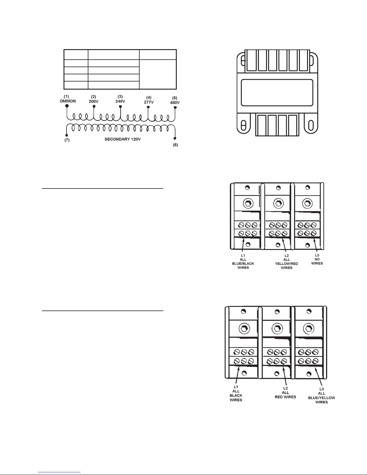
transformer tap change. Immersion thermostat models are equipped with a transformer having 5 connections:
common, 208, 240, 277 and 408 and 2 secondary connections. See the following diagrams.
Only one wire need be changed on the transformer to change voltage. Remove the wire from the terminal
marked 208, 240, 277 or 480 and attach it to the appropriate terminal marked 208, 240, 277 or 480.
C. Do not change the common connections or the secondary wire connections.
4
Page 5
480
277
240
208
COM
IMMERSION THERMOSTAT MODEL TRANSFORMER
CONNECTION TABLES
Volts Line On Load on
208 Common & 208
240 Common & 240 Secondary
277 Common & 277 120V
480 Common & 480
V. PHASE CONVERSION
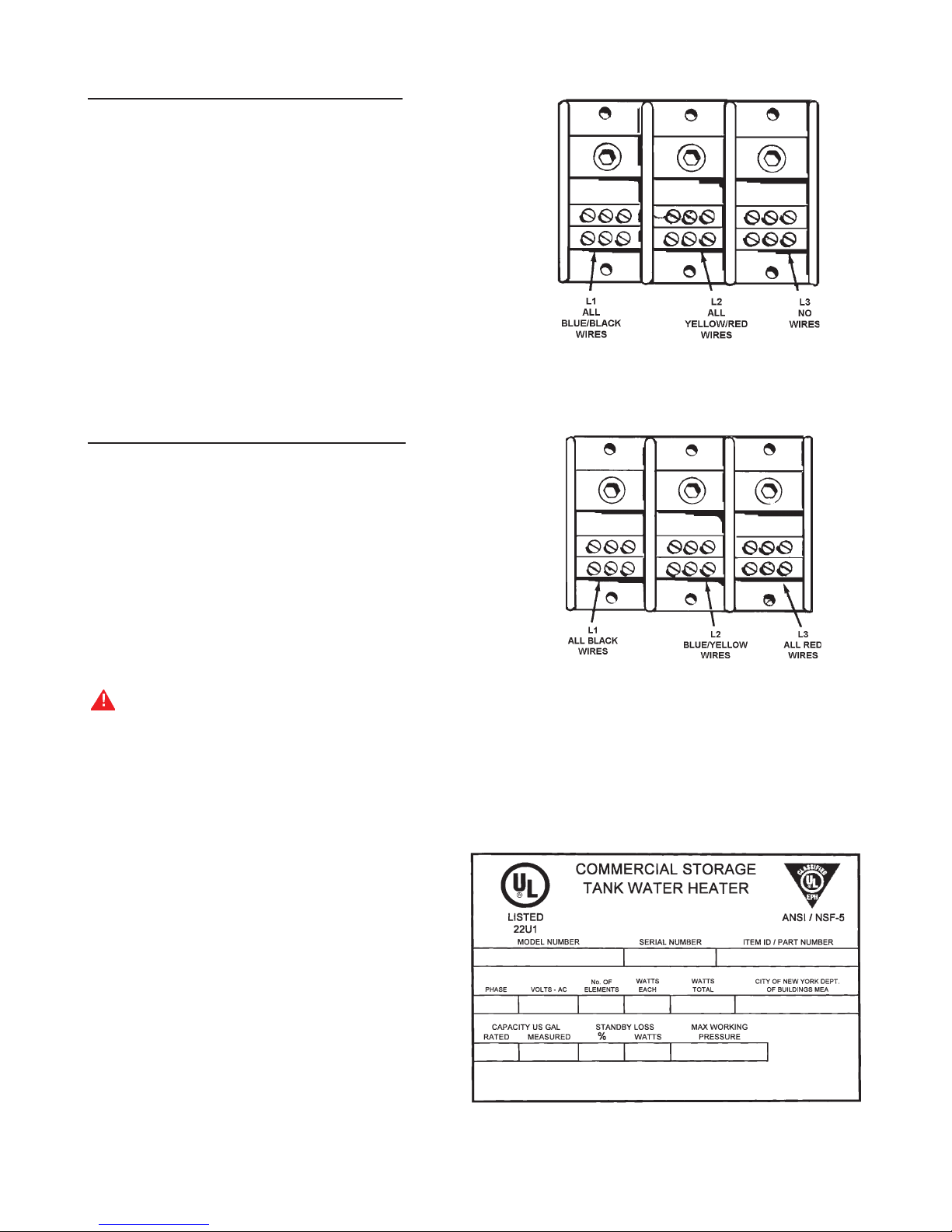
A. IMMERSION THERMOSTAT MODEL
THREE PHASE TO SINGLE PHASE
1. Disconnect blue wires and yellow wires from terminal L-3.
IMMERSION THERMOSTAT MODEL TRANSFORMER
IMMERSION THERMOSTAT MODEL
SINGLE PHASE TERMINAL BLOCK
2. Connect all blue wires to terminal L-1 (with black wires).
3. Connect all yellow wires to terminal L-2 (with red wires).
4. Incoming power will be connected to
terminals L-1 and L-2 at job site.
B. IMMERSION THERMOSTAT MODEL
SINGLE PHASE TO THREE PHASE
1. Disconnect blue wires from terminal L-1.
2. Disconnect yellow wires from terminal L-2.
3. Connect all blue wires and yellow wires to terminal L-3.
4. Incoming power will be connected to terminals
L-1, L-2 and L-3 at job site.
IMMERSION THERMOSTAT MODEL
THREE PHASE TERMINAL BLOCK
5
Page 6
C. SURFACE THERMOSTAT MODEL
THREE PHASE TO SINGLE PHASE
1. Disconnect blue wires from terminal L-2.
2. Connect all blue wires to terminal L-1
(with black wires).
3. Disconnect all red wires from terminal L-3.
4. Connect all red wires to terminal L-2 (with yellow wires).
5. Incoming power will be connected to
terminals L-1 and L-2 at job site.
SURFACE THERMOSTAT MODEL
SINGLE PHASE TERMINAL BLOCK
D. SURFACE THERMOSTAT MODEL
SINGLE PHASE TO THREE PHASE
SURFACE THERMOSTAT MODEL
THREE PHASE TERMINAL BLOCK
1. Disconnect blue wires from terminal L-1
2. Disconnect red wires from terminal L-2.
3. Connect all blue wires to terminal L-2 (with yellow wires).
4. Connect red wires to terminal L-3.
5. Incoming power will be connected to
terminals L-1, L-2 and L-3 at job site.
VI. CAUTION
Recheck all terminals for tightness, proper wiring per schematic, and neatness of wiring, Heater should
be no less than factory constructed quality and appearance.
CHECK ALL WATER AND ELECTRICAL CONNECTIONS FOR TIGHTNESS
VII. FINAL ASSEMBLY
A. CONTROL PANEL
Replace foam door. Cover all elements
and thermostats as originally constructed.
Replace T & P valve package, close door,
relatch and tighten the two control panel screws.
B. RATING PLATE MODIFICATION
Following is a sample of the standard rating
plate supplied on the front of the control panel
door.
SAMPLE RATING PLATE
6
Page 7
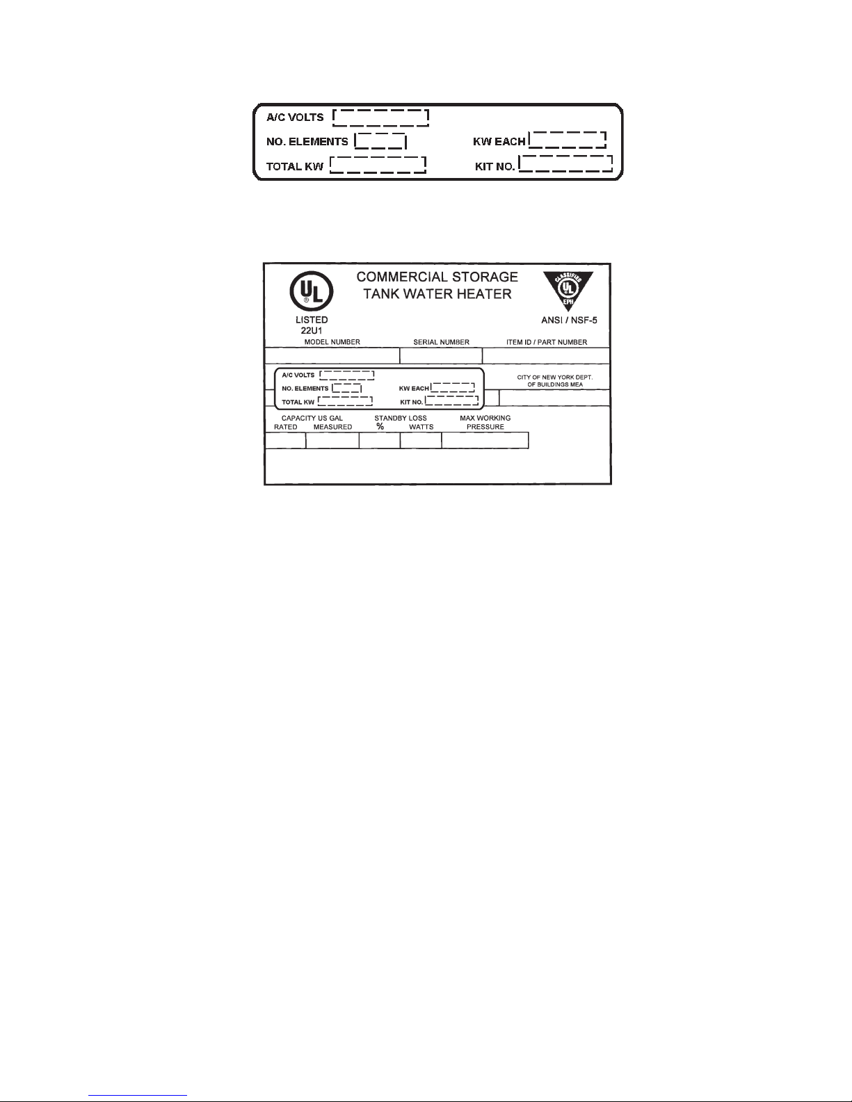
The voltage, element KW, total KW data of the rating plate must be modied by covering them with the label provided in
the conversion kit. Be sure the new ratings on the label match the conversion you have just completed.
Peel off the back of the label and paste over the existing rating plate as shown below.
SAMPLE RATING PLATE WITH CONVERSION LABEL
C. Peel off back of caution label and attach label to upper right hand corner of control panel door.
D. CRATE IDENTIFICATION
Using a black magic marker, cross out heater identication on crate as appropriate. In bold letters, write
new electrical specications in crate, matching those on the revised rating plate.
E. SHIPPING CRATE
Close and tape the plastic ap on front of crate.
CHECK LIST
All affected parts have been installed properly and have been checked for tightness.
All affected wires have been checked for tightness.
New elements have been wired per wiring diagram label on the unit.
New elements have been tightened properly.
New elements have been leak checked.
New rating plate overlay has been installed properly over the existing rating plate.
VIII. MISCELLANEOUS INFORMATION.
A. NON STANDARD CONSTRUCTION
At 480 and 240 volts, 18KW is normally supplied using three 6,000 watt elements. They can however, be
constructed using six 3,000 watt elements.
At 480 volts and 240 volts, 36KW is normally supplied using six 6,000 watt elements. It can however, be supplied
using nine 4,000 watt elements.
7
Page 8
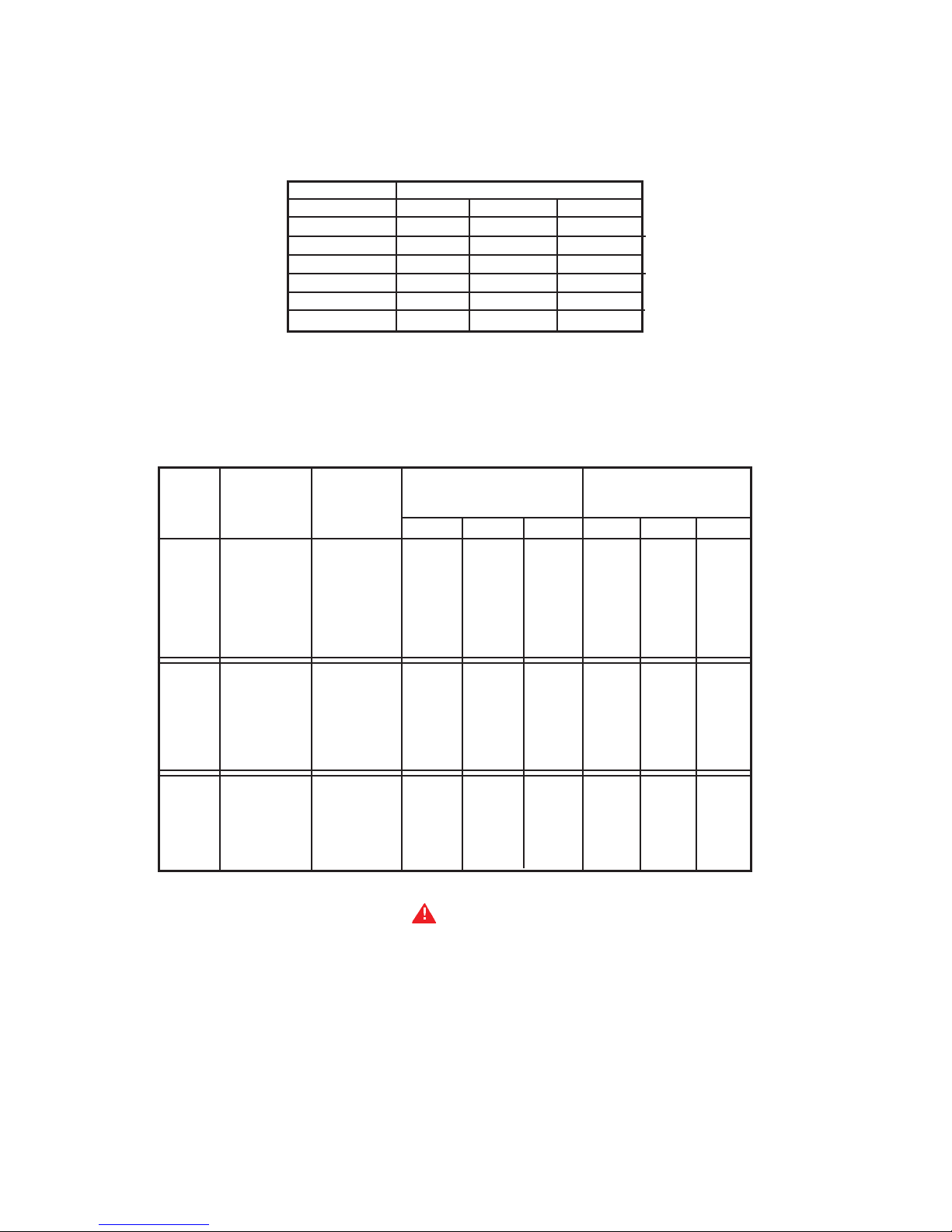
B. ELEMENT SIZE VERIFICATION
All elements are marked with both wattage and voltage. Verication can be made by measuring the ohms
resistance across the terminals of the elements. Element must be disconnected from the circuit. The following
table gives resistance in ohms for all elements used in commercial electric water heaters.
OHMS RESISTANCE TABLE
VOLTAGE
WATTAGE 208 240 480
2000 21.63 28.80 115.20
3000 14.42 19.20 76.80
4000 10.82 14.40 57.60
4500 9.61 12.80 51.20
5000 8.65 11.52 46.08
6000 7.21 9.60 38.40
Element ohms resistance should be within ±5% of the above values.
Examples: Elements with an ohm resistance of 14 ohms indicates that it is either a 3,000 watt/208 volt element
and/or a 4,000 watt/240 volt element (dual rated type).
FULL LOAD CURRENT IN AMPERES
Number KW Single (1) phase Three (3) Phase
KW of Each
Input Elements Elements 208V 240V 480V 208V 240V 480V
6 2.0 28.8 25.0 12.5 16.7 14.4 7.2
9 3.0 43.3 37.5 18.8 25.0 21.7 10.8
12 4.0 57.7 50.0 25.0 33.3 28.9 14.4
13.5 4.5 64.9 56.3 28.1 37.5 32.5 16.2
15 5.0 72.1 62.5 31.3 41.6 36.1 18..0
18 6.0 - - - - 75.0 37.5 - - - - 43.3 21.7
3
18 3.0 86.5 - - - - - - - - 50.0 - - - - - - - 24 4.0 115.4 100.0 50.0 66.6 57.7 18.9
27 4.5 129.8 112.5 56.3 74.9 65.0 32.5
30 5.0 144.2 125.0 62.5 83.3 72.2 36.1
36 6.0 - - - - 150.0 75.0 - - - - 86.6 43.3
36 4.0 173.1 - - - - - - - - 99.9 - - - - - - - -
40.5 4.5 194.7 168.8 84.4 112.4 97.4 48.7
45 5.0 216.3 187.5 93.8 124.9 108.3 54.1
54 6.0 - - - - 225.0 112.5 - - - - 129.9 65.0
NEVER OPERATE THE HEATER WITHOUT FILLING WITH WATER PER THE FILLING INSTRUCTIONS. FAILURE
TO DO SO WILL DAMAGE INTERNAL PARTS.
6
9
CAUTION
8
Page 9

NOTES
9
Page 10

NOTES
10
Page 11

NOTES
11
Page 12

125 Southeast Parkway
Franklin, TN 37068
1-800-433-2545
apcom-inc.com
12
 Loading...