

Page 1

Service Manual
APC Smart-UPS® RT
3,000VA – 10,000VA 200-240 Vac
Uninterruptible Power Supply
English
Tower/Rack Mount
SURT 3kVA-10kVA Service Manual 1
2005 American Power Conversion. All rights reserved. No part of this publication may be used, reproduced,
photocopied, transmitted, or stored in any retrieval system of any nature, without the written permission of the
copyright owner. www.apc.com Rev 2005-2
Page 2

Table of Contents
1 Safety Precautions...........................................................................................................................................3
2 Introduction to SURT......................................................................................................................................4
2.1 Key Points........................................................................................................................................... 4
2.2 One-Line Diagram ..............................................................................................................................4
2.3 Main Circuit Components...................................................................................................................4
2.4 Functional Description........................................................................................................................ 5
2.5 Power Train Operation........................................................................................................................5
2.6 Transistor-Level Diagrams .................................................................................................................6
3 User Interface................................................................................................................................................ 11
3.1 Front Panel Display and Control Buttons ......................................................................................... 11
3.2 Terminal Mode..................................................................................................................................13
3.3 SmartSlot Accessories (Webcard).....................................................................................................15
4 Installation.....................................................................................................................................................16
5 Component Replacements.............................................................................................................................16
6 Troubleshooting ............................................................................................................................................ 17
6.1 Unit Setup .........................................................................................................................................17
6.2 Required Tools.................................................................................................................................. 17
6.3 Visual Inspections.............................................................................................................................17
6.4 Troubleshooting Flowchart...............................................................................................................18
6.5 Diode Checks....................................................................................................................................20
6.6 Documenting Failures.......................................................................................................................25
7 ECO's ............................................................................................................................................................25
8 Test After ECO's...........................................................................................................................................26
Appendix A. Fault codes on LED display & stored in EEPROM....................................................................28
Appendix B. ECO list as of October, 2005.......................................................................................................33
SURT 3kVA-10kVA Service Manual 2
2005 American Power Conversion. All rights reserved. No part of this publication may be used, reproduced,
photocopied, transmitted, or stored in any retrieval system of any nature, without the written permission of the
copyright owner. www.apc.com Rev 2005-2
Page 3
1 Safety Precautions
Read and adhere to the following warnings when installing or servicing a UPS and/or battery packs.
Failure to observe these warnings may result in serious injury, death or damage to the equipment.
WARNINGS
PRACTICES
• Do not attempt to install or service external batteries alone. A qualified
electrician should perform the installation and servicing of external
batteries.
• Disconnect charging source(s) BEFORE connecting or disconnecting
battery terminals.
• External batteries may retain lethal voltages after power has been
disconnected and all switches are off.
• Use extreme caution when making terminal connections. Do not allow
cables to touch anything except the intended terminal.
Always wear:
• Goggles or face shields
• Acid-resistant, insulated gloves
• Protective aprons
• Protective overshoes or rubber boots
Always use:
• Insulated tools
• Rubber mats to cover batteries during servicing
• Rubber mats or rubber stands on the floor
• Adequate lifting devices
Remove:
• Watches, rings, and other metal objects from your body
PRECAUTIONS
SURT 3kVA-10kVA Service Manual 3
2005 American Power Conversion. All rights reserved. No part of this publication may be used, reproduced,
photocopied, transmitted, or stored in any retrieval system of any nature, without the written permission of the
copyright owner. www.apc.com Rev 2005-2
• To avoid static build-up, service personnel should establish a grounding
contact prior working on batteries.
• Do not lay tools or metal parts on top of batteries.
• Lead-acid batteries contain hazardous, toxic materials.
§ Do not open, alter or mutilate batteries. Internal materials may be
harmful to the skin and eyes.
§ Do not dispose of batteries in a fire. There is danger of explosion.
• Handle, transport and recycle batteries in accordance with local codes
and regulations.
Page 4
2 Introduction to SURT
2.1 Key Points
• Double-conversion online topology
• Inverter voltage is selectable through communication only: 200V, 208V, 220V, 230V, 240V.
• Bypass “acceptable voltage” window changes with Inverter voltage setting.
• Batteries must be connected to start UPS. After startup, batteries can be safely removed and replaced
without interruption to the output.
• Lynx2 (3kVA – 6kVA) has single battery (192V nominal) referenced to output Neutral.
• Lynx3 (7.5kVA – 10kVA) has two battery strings (+192V and -192V nominal) managed independently and
charged with separate chargers.
• Lynx3 (7.5kVA – 10kVA) can accept single-phase or three-phase input voltage. In both cases, Bypass is only
single-phase (“L1” and “N” inputs) so the input wiring must be sized to handle full-load current as singlephase.
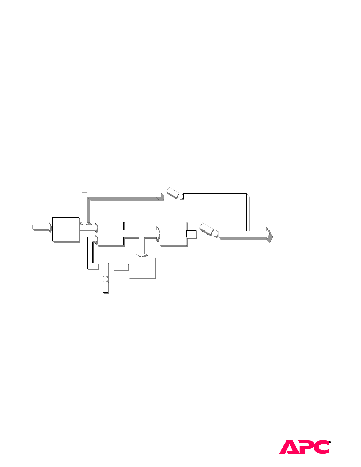
2.2 One-Line Diagram
160 -284
VAC Input
Input
Filter
Section
Rectifier &
PFC
+/- DC Bus
Inverter
Output
Section
Battery
Charger
192 VDC
Battery
2.3 Main Circuit Components
The primary sections of the UPS are:
• Input disconnect and filter stage
• Input Power Factor Correction (PFC) power stage
• Energy storage stage (dc bus capacitor bank)
• Output power stage (inverter)
• Bypass
• Battery charger
• Battery: 1 or 2 strings each connected to output Neutral
Bypass
Switch
240 VAC
Output
SURT 3kVA-10kVA Service Manual 4
2005 American Power Conversion. All rights reserved. No part of this publication may be used, reproduced,
photocopied, transmitted, or stored in any retrieval system of any nature, without the written permission of the
copyright owner. www.apc.com Rev 2005-2
Page 5

2.4 Functional Description
The control of power module and fault detection logic is uP based. The input filter stage contains input backfeed relays,
input EMI filter, transient suppression, and battery select transfer relays. Input PFC power stage contains non-isolated
power factor correcting AC/DC converters. PFC converter is split in two power sections – positive and negative boost
stage – while operating on-line and in positive boost and buck boost power stage while operating on battery. This
converter is capable of full power operation from 160 to 280 VAC line to neutral or from a nominal DC battery voltage of
192VDC. The output from this stage is a +/-395V center tapped dc bus. The energy storage stage is split DC bus
capacitor handling seamless transitions from battery to line and vice versa as well as the low and high frequency power
stages ripple. The inverter stage operates directly from +/- 395VDC bus and produces an AC output voltage of
200/208/220/230/240Vac (for NAM and EMEA) or 200Vac (for Japan). The output of the UPS is either connected through
a pair of relays either to the inverter or to the input filtered line. The UPS contains 1 or 2 battery chargers, each rated
400W.
2.5 Power Train Operation
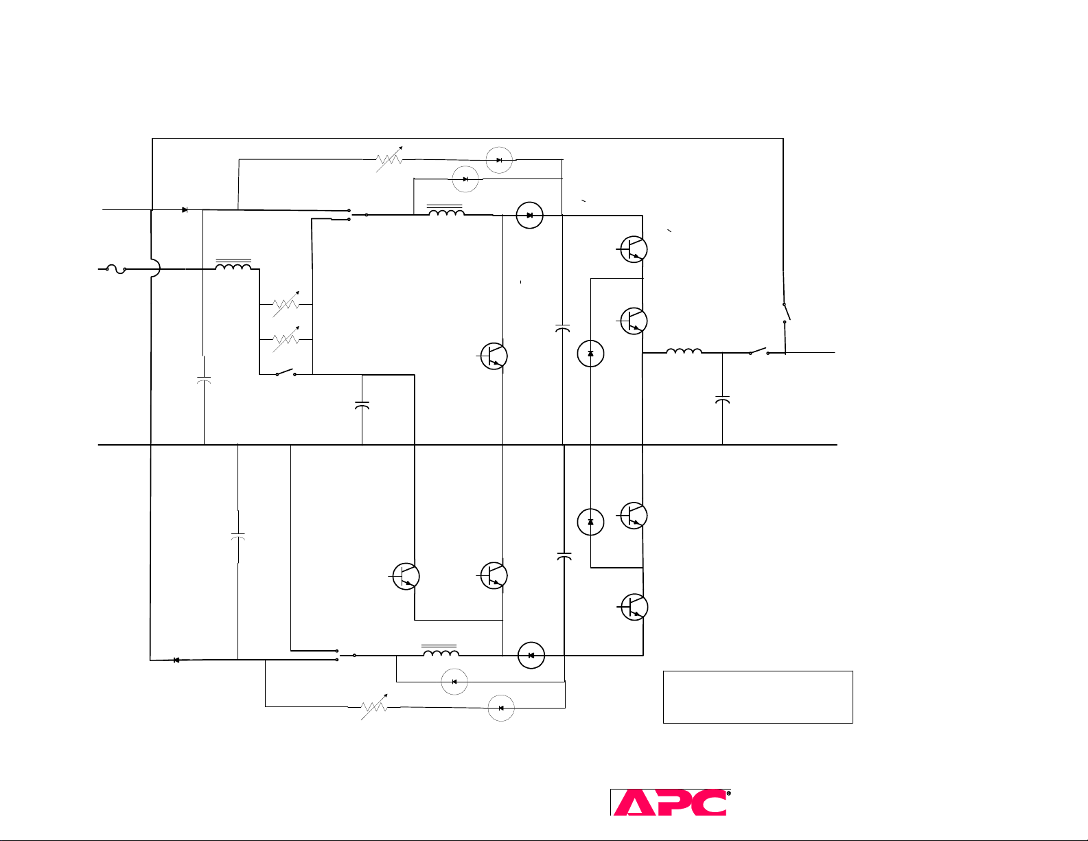
When operating on line, the input voltage is first rectified so two half wave rectified voltage waveforms are produced in
reference to the Neutral. Positive line rectified signal is fed to positive boost PFC stage. This stage is a boost type
converter which converts positive half rectified input signal into DC positive bus voltage of +395V, drawing the input
current in phase with positive half cycle of the line current. The boost stage consists of an input choke, high frequency
IGBT switch, high frequency soft recovery diode and the output electrolytic capacitor. The positive boost stage is
bypassed by a low power diode which serves as the boost converter protection in the case of sudden line overshoots and
overvoltages or any other condition which causes input line peak voltage to be higher than DC bus capacitor voltage. The
negative line rectified signal is fed to negative PFC stage. This stage is also boost type converter and operates in the
same manner as the positive PFC boost stage. This stage converts negative line half rectified voltage to negative DC bus
voltage of -395V. The bottom line is that when operating on line both PFC stages are operating as boost converters each
processing half of the total output power per phase.
When operating on battery, the transfer relays connect the PFC to a DC voltage from the battery. The battery voltage is
fed through a filter and inrush stage to both positive and negative PFC stages. The battery filter consists of chokes and
two electrolytic capacitors. The function of the filter is to prevent high frequency ripple from PFC stage going back to
battery and to provide differential mode filter for high frequency noise emanating from battery buses or cables (in case of
external battery packs). The inrush stage as its name says during startup limits the battery inrush current. When the
battery is connected to the input of the PFC stage, the battery filter capacitor and positive DC bus capacitor charging
current is limited through two 50 ohm PTC resistors. When capacitors are charged to battery voltage inrush relays are
switched into closed position bypassing the PTC resistors. The positive PFC stage operates as a DC/DC boost converter
and converts battery voltage to DC bus voltage. The operation in this mode is the same as operation on line as described
above, except that current drawn from battery is now DC current. The negative PFC stage operates as buck boost stage
and converts battery voltage to negative DC bus voltage.
The output stage of the UPS consists of inverter with output filter and bypass relays. This stage is a DC/AC converter
which function is to convert DC bus voltages into regulated output sine wave voltage. The inverter uses a neutral point
clamp topology and consists of the top and bottom section. The top section converts positive DC bus voltage of 395V into
positive half wave sine voltage and bottom portion converts negative DC bus voltage into negative half sinewave voltage.
The PWM control of inverter regulates the frequency and amplitude of the output AC voltage. The output filter consists of
a smoothing choke and a filter capacitor. The filtered voltage is fed through a NO relay contact to the UPS output.
SURT 3kVA-10kVA Service Manual 5
2005 American Power Conversion. All rights reserved. No part of this publication may be used, reproduced,
photocopied, transmitted, or stored in any retrieval system of any nature, without the written permission of the
copyright owner. www.apc.com Rev 2005-2
Page 6
2.6 Transistor-Level Diagrams
Lynx2: 3kVA – 6kVA
D22
Input 160-280Vac
BATTERY 192V
L101
50 OHM
50 OHM
K1
LINE
BATTERY
K3
C6//C8
Q6//Q7
L8
Q2//Q3
D14
C12//C13
Q4//Q5
D23
Q11
Q12//Q13
L4+L5+L6
C27//C28
Q14//Q15
D24
BATTERY
LINE
L7
K4
D19
D15
SURT 3kVA-10kVA Service Manual 6
2005 American Power Conversion. All rights reserved. No part of this publication may be used, reproduced,
photocopied, transmitted, or stored in any retrieval system of any nature, without the written permission of the
copyright owner. www.apc.com Rev 2005-2
Q16
Lynx II POWER TRAIN
Page 7
SURT 3kVA-10kVA Service Manual 7
2005 American Power Conversion. All rights reserved. No part of this publication may be used, reproduced,
photocopied, transmitted, or stored in any retrieval system of any nature, without the written permission of the
copyright owner. www.apc.com Rev 2005-2
Page 8
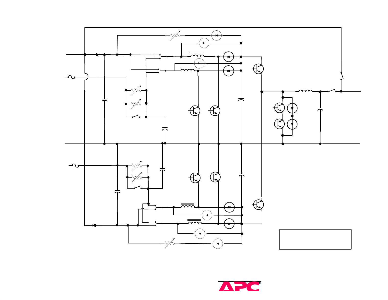
Lynx3: 7.5kVA – 10kVA (interleaved PFC)
Bypass
Input 160-280Vac
50/60Hz
BATTERY
NEUTRAL
BATTERY
-192V
+192V
50 OHM
50 OHM
LINE
BATTERY
Inverter output
200-240Vac
50/60Hz
BATTERY
LINE
SURT 3kVA-10kVA Service Manual 8
2005 American Power Conversion. All rights reserved. No part of this publication may be used, reproduced,
photocopied, transmitted, or stored in any retrieval system of any nature, without the written permission of the
copyright owner. www.apc.com Rev 2005-2
Lynx3 POWER TRAIN
Page 9
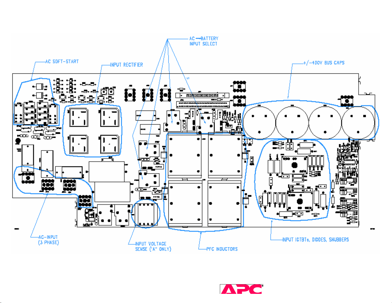
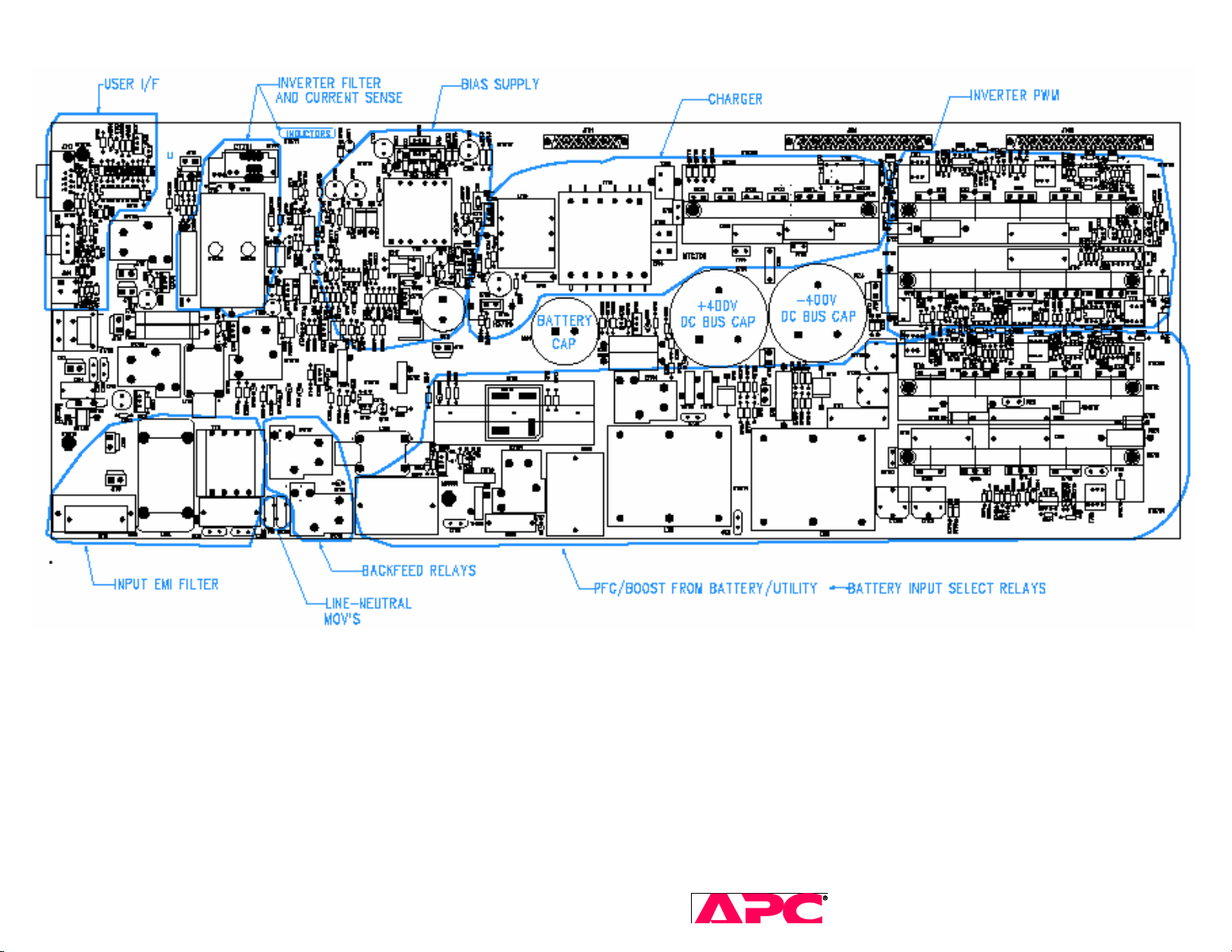
Lynx3 PFC power board, 640-0761 – Circuit locations
SURT 3kVA-10kVA Service Manual 9
2005 American Power Conversion. All rights reserved. No part of this publication may be used, reproduced,
photocopied, transmitted, or stored in any retrieval system of any nature, without the written permission of the
copyright owner. www.apc.com Rev 2005-2
Page 10
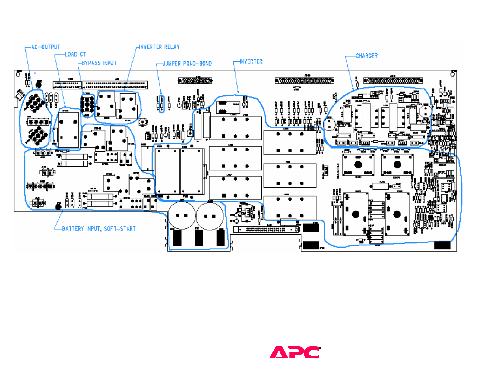
Lynx3 INVERTER power board, 640-0762
SURT 3kVA-10kVA Service Manual 10
2005 American Power Conversion. All rights reserved. No part of this publication may be used, reproduced,
photocopied, transmitted, or stored in any retrieval system of any nature, without the written permission of the
copyright owner. www.apc.com Rev 2005-2
Page 11
3 User Interface
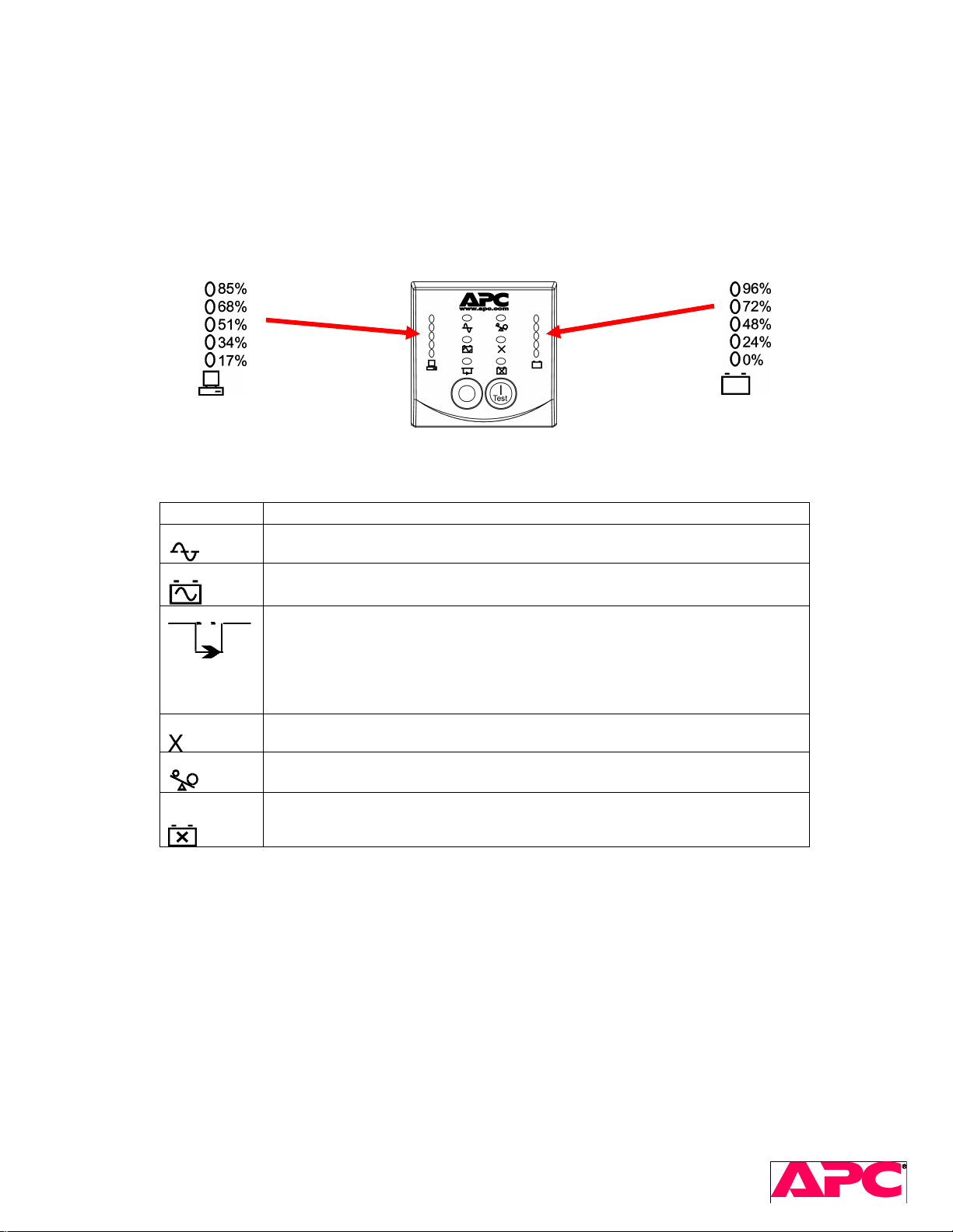
3.1 Front Panel Display and Control Buttons
The front panel contains status and diagnostic LEDs and two control buttons. Several of the LEDs comprise bar
graphs that display status and diagnostic information according to the table below.
Load Smart-UPS RT Front Display Battery Charge
Indicator Description
Online
On Battery
The Online LED illuminates when the UPS is drawing utility power and
performing double conversion to supply power to connected equipment.
The UPS is supplying battery power to the connected equipment.
Bypass
Fault
Overload
The Bypass LED illuminates indicating that the UPS is in bypass mode.
Utility power is sent directly to connected equipment during bypass mode
operation. Bypass mode operation is the result of an internal UPS fault, an
overload condition or a user initiated command either through an accessory
or the manual bypass switch. Battery operation is not available while the
UPS is in bypass mode. Refer to Troubleshooting in this manual.
The UPS detects an internal fault.
Refer to Troubleshooting in this manual.
An overload condition exists. See Troubleshooting.
Replace
Battery
The battery is disconnected or must be replaced. See Troubleshooting.
Table 1. Front Panel LEDs.
SURT 3kVA – 10kVA Service Manual 11
2005 American Power Conversion. All rights reserved. No part of this publication may be used, reproduced,
photocopied, transmitted, or stored in any retrieval system of any nature, without the written permission of the
Page 12
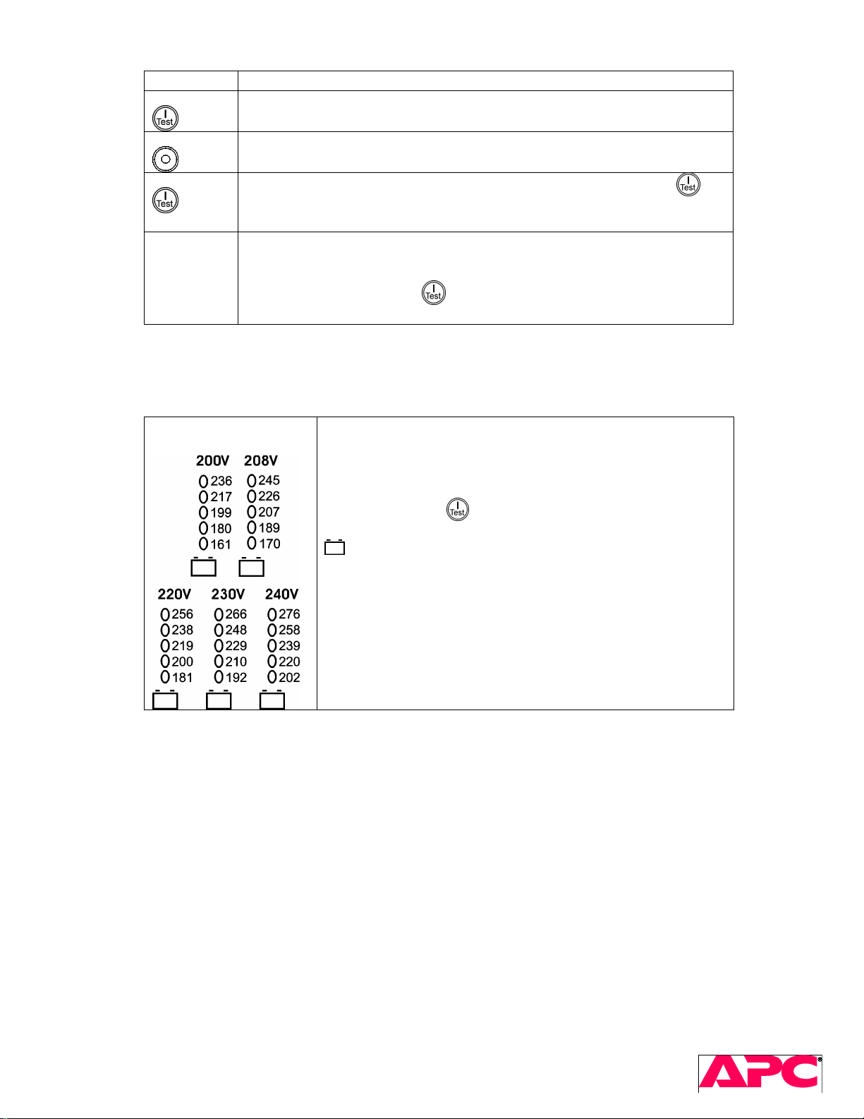
Feature Function
Power On
Press this button to turn on the UPS. (See below for additional capabilities.)
Power Off
Press this button to turn off the UPS.
Cold Start
Self-Test
Table 2. Front Panel Control Pushbuttons.
When there is no utility power and the UPS is off, press and hold the
button to power up the UPS and connected equipment.
The UPS will emit two beeps. During the second beep, release the button.
Automatic: The UPS performs a self-test automatically when turned on, and
every two weeks thereafter (by default). During the self-test, the UPS briefly
operates the connected equipment on battery.
Manual: Press and hold the button for a few seconds to initiate the selftest.
Diagnostic Utility
Voltage
The UPS has a diagnostic feature that displays the utility
voltage applied to the UPS.
The UPS starts a self-test as part of this procedure. The selftest does not affect the voltage display.
Press and hold the button to view the utility voltage bar
graph display. After a few seconds the five-LED, Battery Charge
display on the right of the front panel shows the utility input
voltage.
Refer to the figure at left for the voltage reading (values are not
listed on the UPS).
The display indicates the voltage is between the displayed
value on the list and the next higher value.
Table 3. Front Panel Bar Graphs.
SURT 3kVA – 10kVA Service Manual 12
2005 American Power Conversion. All rights reserved. No part of this publication may be used, reproduced,
photocopied, transmitted, or stored in any retrieval system of any nature, without the written permission of the
Page 13
3.2 Terminal Mode
SURT can be configured in a number of ways: Network Management Card web interface, PowerChute ® Software,
Terminal Mode, or UPS-Link commands.
To access Terminal Mode, you will need:
- A computer with an RS-232 serial port
- A terminal application such as Hyperterminal
- An APC black cable 940-0024C (included with the UPS)
Make sure that no SmartSlot accessory is installed in the SmartSlot bay of the UPS. The SmartSlot
prevents access to certain UPS communication features such as the Terminal Mode.
Using a standard APC serial cable (APC part number 940-0024C), connect the computer serial
port to the back of the UPS.
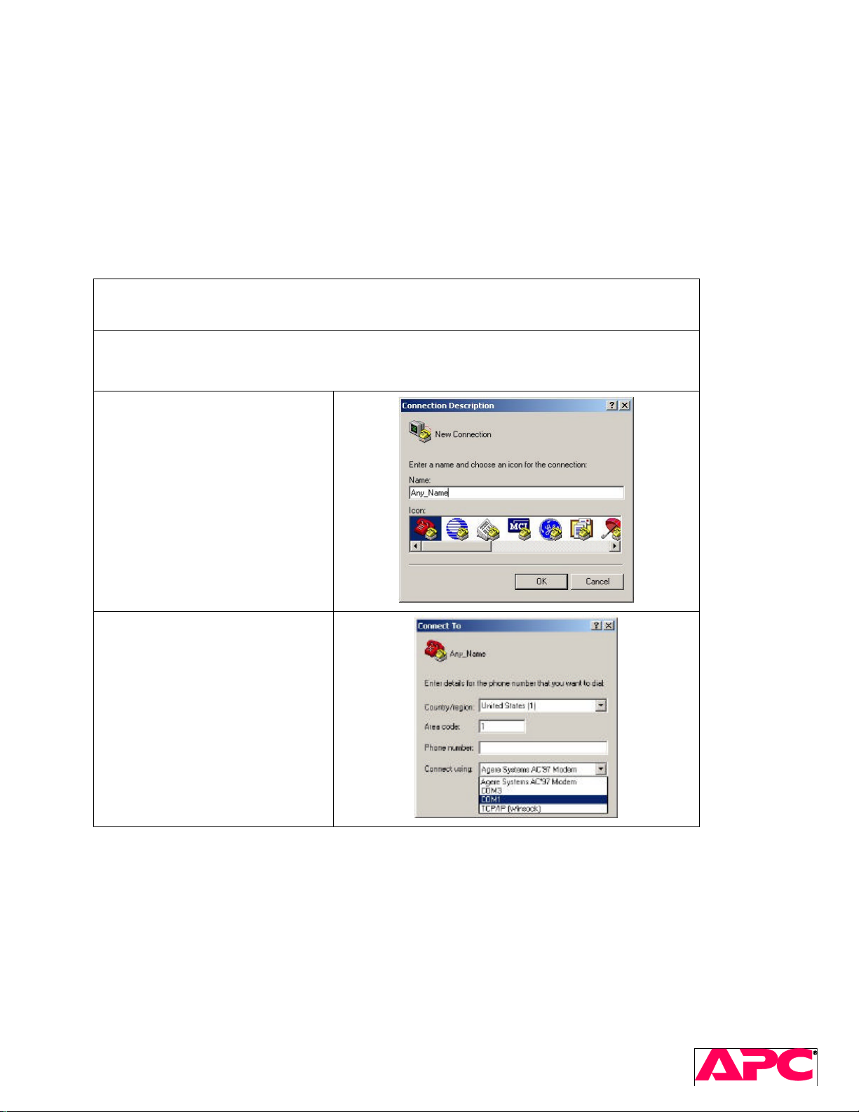
Open a terminal program. Hyperterminal example:
From the Desktop, go to Start => Programs => Accessories => Communication
=>HyperTerminal.
The “Connection Description” dialog
box appears. Enter a name for this
connection and select any icon for
it.
Click [OK]
The “Connect To” dialog box
appears. In the “Connect using”
drop-down list select the COM port
you’re going to use to communicate
with the UPS.
If you get a message that this port
is used by another application then
either use a different COM port or
close the application using the
intended port.
Click [OK]
SURT 3kVA – 10kVA Service Manual 13
2005 American Power Conversion. All rights reserved. No part of this publication may be used, reproduced,
photocopied, transmitted, or stored in any retrieval system of any nature, without the written permission of the
Page 14
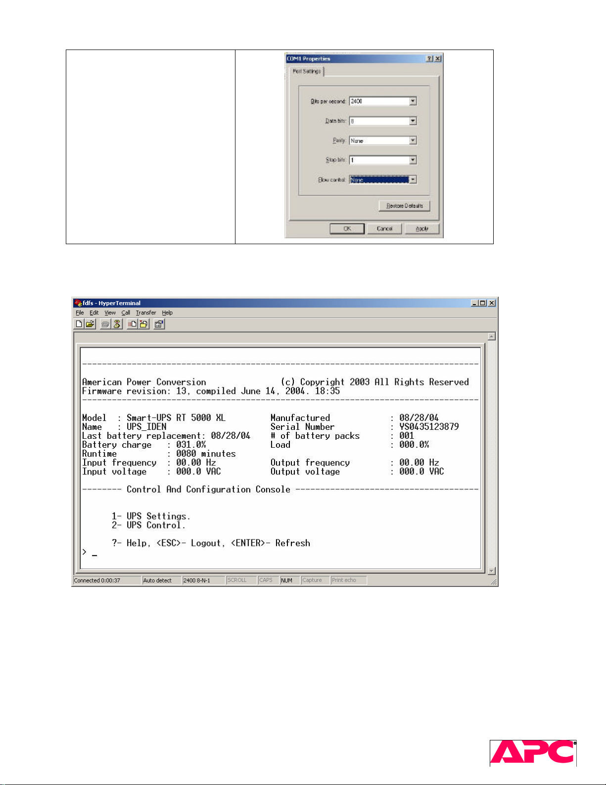
In the communication settings
dialog box, select the following
settings:
Bits per second: 2400
Data bits: 8
Parity: Note
Stop bits: 1
Flow control: None
Click [OK]
Press the Enter key. The root terminal mode menu will appear, similar to the following:
To configure the UPS, press the 1 key. The UPS will chirp and the “UPS Settings” menu will appear.
SURT 3kVA – 10kVA Service Manual 14
2005 American Power Conversion. All rights reserved. No part of this publication may be used, reproduced,
photocopied, transmitted, or stored in any retrieval system of any nature, without the written permission of the
Page 15
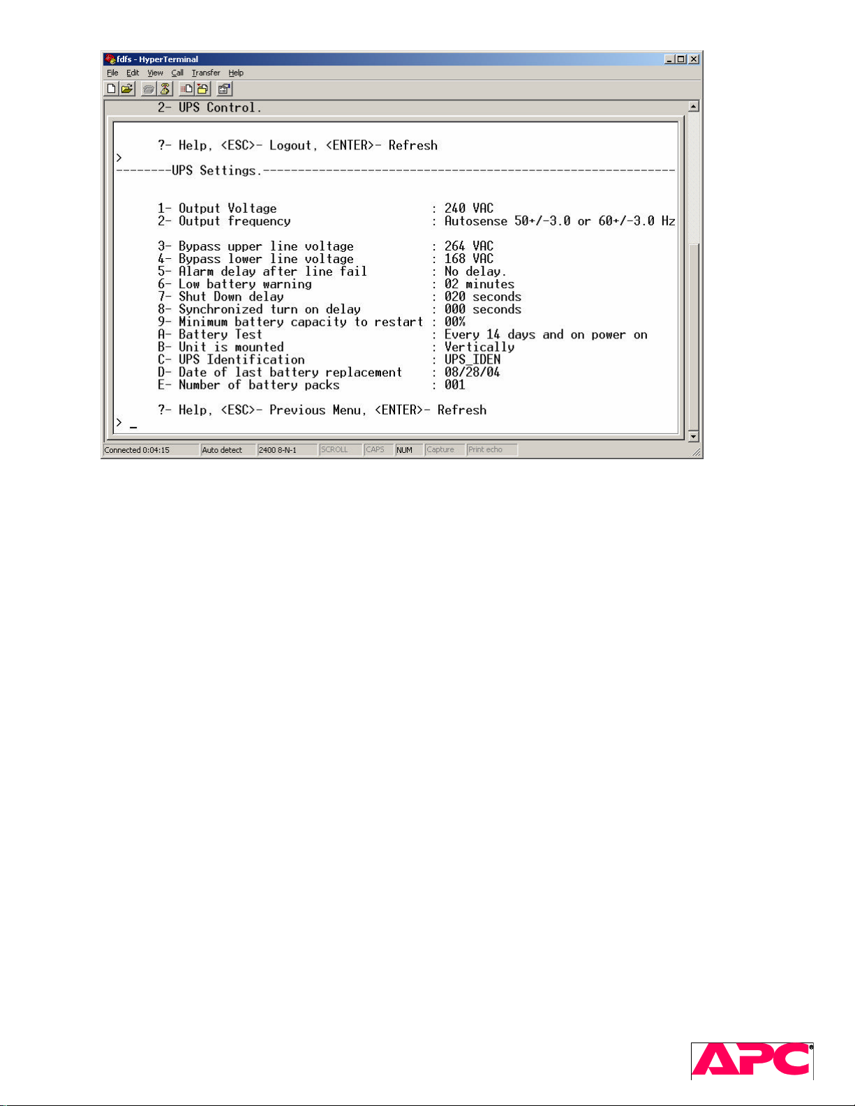
To change a setting, press the corresponding key (not case-sensitive) and follow the instructions.
Please note that if no key is pressed for approximately 5 minutes, the Terminal Mode session will time out and you’ll have
to press Enter and start from the root menu again.
3.3 SmartSlot Accessories (Webcard)
SURT models include a standard SmartSlot that is compatible with accessories used in other APC products.
Notes on “event log” entries in the AP9619 (NMC or “webcard”):
• Almost all internal UPS faults are recorded as "Bad output voltage" regardless of whether or not the
detected fault is related to the Inverter or Bypass. The NMC is not able to differentiate between the
different UPS failure codes.
• "Battery charger failure" could be a momentary battery overvoltage condition -- see if this alarm is cleared
within 2 seconds in the log.
SURT 3kVA – 10kVA Service Manual 15
2005 American Power Conversion. All rights reserved. No part of this publication may be used, reproduced,
photocopied, transmitted, or stored in any retrieval system of any nature, without the written permission of the
Page 16
4 Installation
See User Manual included with the UPS for installation precautions and instructions.
Installation troubleshooting: Make sure:
• each battery string is above 175V (there are two battery modules per string)
• all battery modules are securely connected
• input AC is connected correctly, input phase_select switch set correctly to 1 or 3 (if exists)
• input breaker closed (if exists)
• output breakers on (if exist)
5 Component Replacements
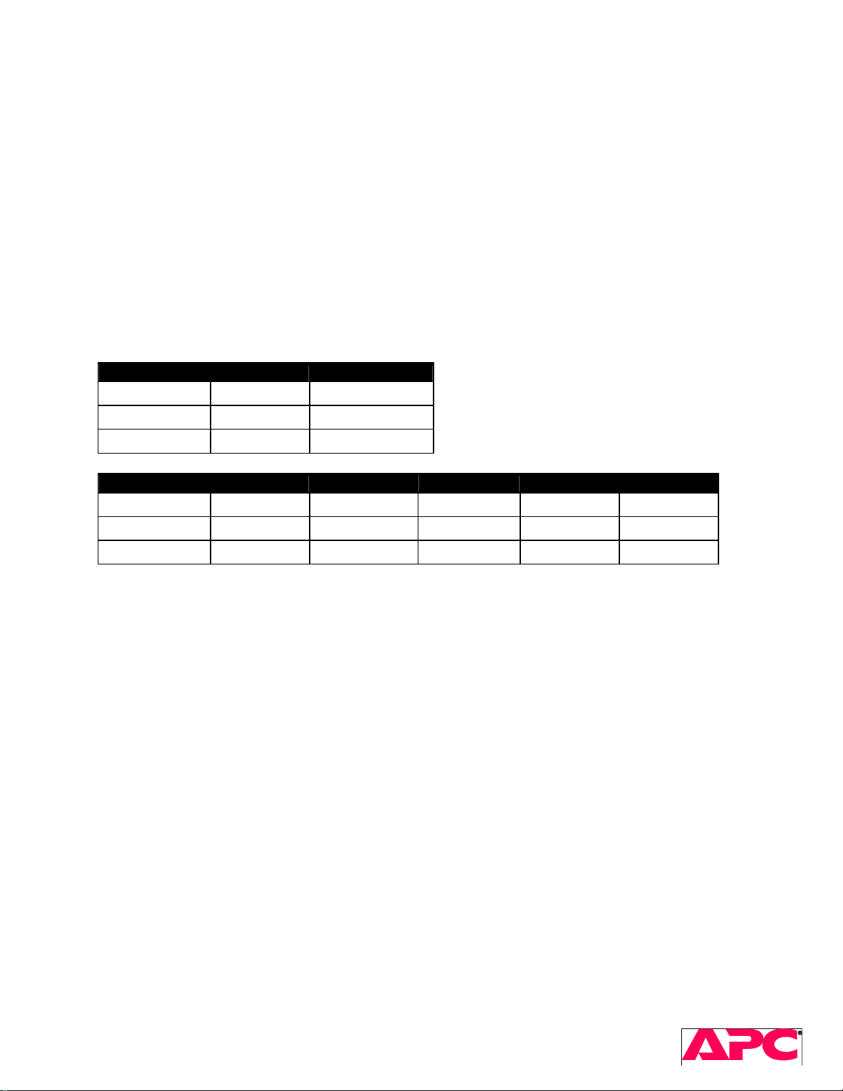
Replacement boards:
SKU Power Board Control Board
SURT3000
SURT5000
SURT6000
SKU PFC power Inverter power Main Control Aux Control Bias & I/O
SURT7500
SURT8000
SURT10000
Battery modules (RBC44?) – one for Lynx2, two for Lynx3?
Bezels w/ stickers
Display PCB/bezel assemblies
Fan for Lynx2
Fan for Lynx3
Battery fuses: (515-1030A)
See ??? for optional PDU’s including H/W kit for Lynx2 output
0P7510 0P7603
0P7510 0P7600
0P7516 0P7606
0P7611 0P7621 0P7507 0P7631 0P7641
0P7611 0P7621 0P7608 0P7631 0P7641
0P7611 0P7621 0P7501 0P7631 0P7641
SURT 3kVA – 10kVA Service Manual 16
2005 American Power Conversion. All rights reserved. No part of this publication may be used, reproduced,
photocopied, transmitted, or stored in any retrieval system of any nature, without the written permission of the
Page 17

6 Troubleshooting
Safety: Remove jewelry, pendants and wrist watches.
6.1 Unit Setup
Unpack the UPS and put it on a flat even surface (mind OSHA regulations). Check the packaging for any signs of
damage.
Lynx2
Net Weight 120.00 lbs. ( 54.55 kg)
Shipping Weight 140.00 lbs. ( 63.64 kg)
Note: Follow all environmental regulations. Discard old batteries in an environmentally friendly way. Be sure to deliver
spent batteries to a recycling facility or ship to the manufacturer in the replacement battery packing material.
6.2 Required Tools
• Digital multimeter (for example, Fluke 87)
• Power resistor to discharge capacitors
• Serial communication cable (RS-232)
• Communication software (for example, laptop and “Hyperterminal” software in Windows)
• Phillips screwdriver
• AC power supply
• Load
6.3 Visual Inspections
Visual inspection is often overlooked but is one of the most important steps in diagnosing a problem. It can also
save a lot of time.
Exterior
Check the packaging and exterior of the UPS for any physical damage
1. Plastic bezels
2. Fan guard & blades
3. Bent sheet metal
4. PDU breakers
Interior
Check all wiring, connections, and PCB components
1. Wire insulation broken
2. Burned components and/or burned marks on PCB
3. Daughter PCBs not tight in sockets
4. Components touching chassis or other components (esp. small heatsinks, power resistor leads)
5. Leads not clipped properly, solder-bridges (solder-side of PCB)
SURT 3kVA – 10kVA Service Manual 17
2005 American Power Conversion. All rights reserved. No part of this publication may be used, reproduced,
photocopied, transmitted, or stored in any retrieval system of any nature, without the written permission of the
Page 18
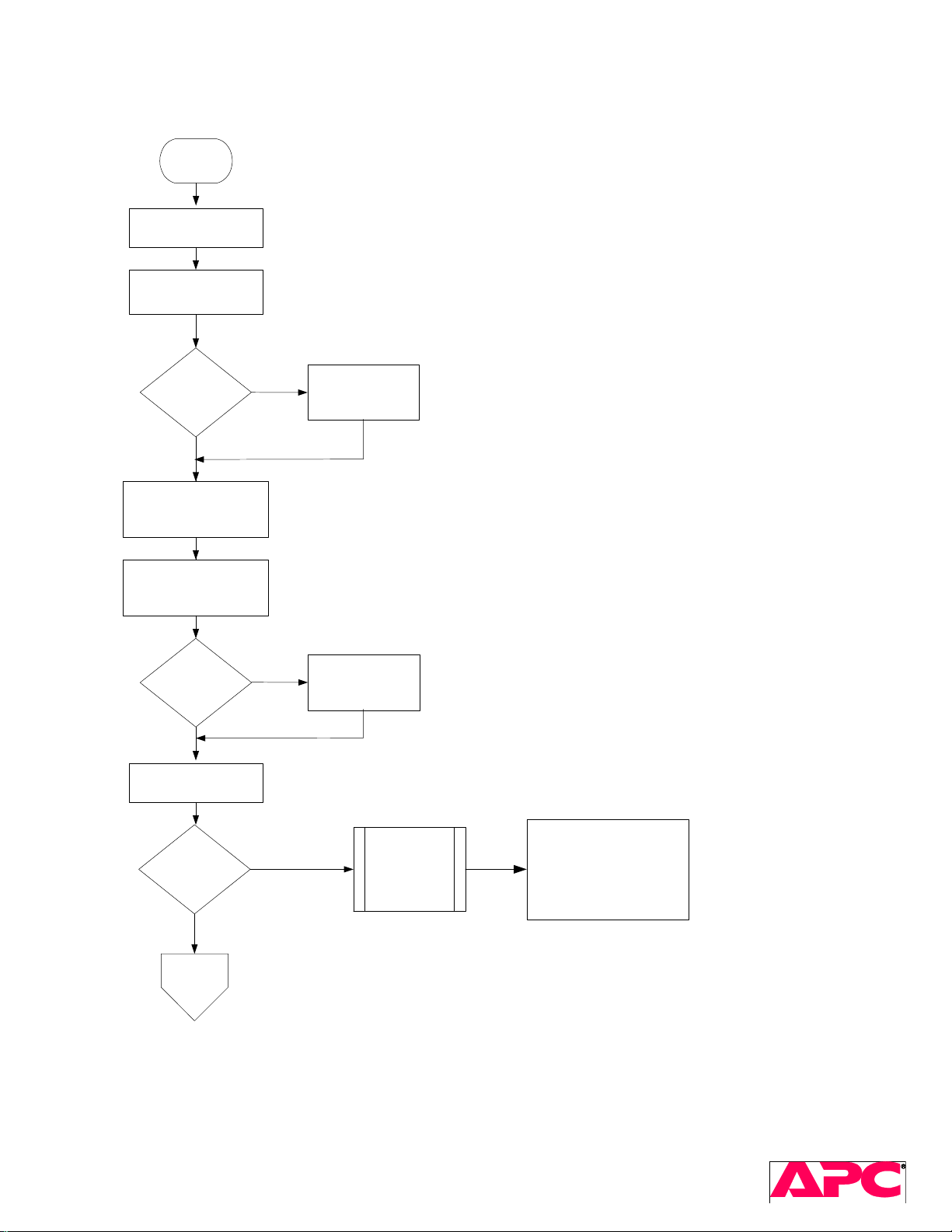
6.4 Troubleshooting Flowchart
Start
Visual inspection
(exterior)
Make sure all battery
packs disconnected
Each
Battery pack
>84V?
Yes
Remove top panel,
Discharge all caps
Visual inspection
(interior)
Diode
checks OK?
Yes
Connect Battery,
Push ON-Switch
No
No
Replace battery
pack(s)
Repair & record
failed parts
Lynx 2: Check
Brains on?
(Fan on)
Yes
(next
page)
No
Troubleshoot
LPS
D781, D782, D776, D777,
D778, D779, Q712
Lynx 3: Check D704, D705,
D706, D707, D714, D718,
D722, Q704
SURT 3kVA – 10kVA Service Manual 18
2005 American Power Conversion. All rights reserved. No part of this publication may be used, reproduced,
photocopied, transmitted, or stored in any retrieval system of any nature, without the written permission of the
Page 19
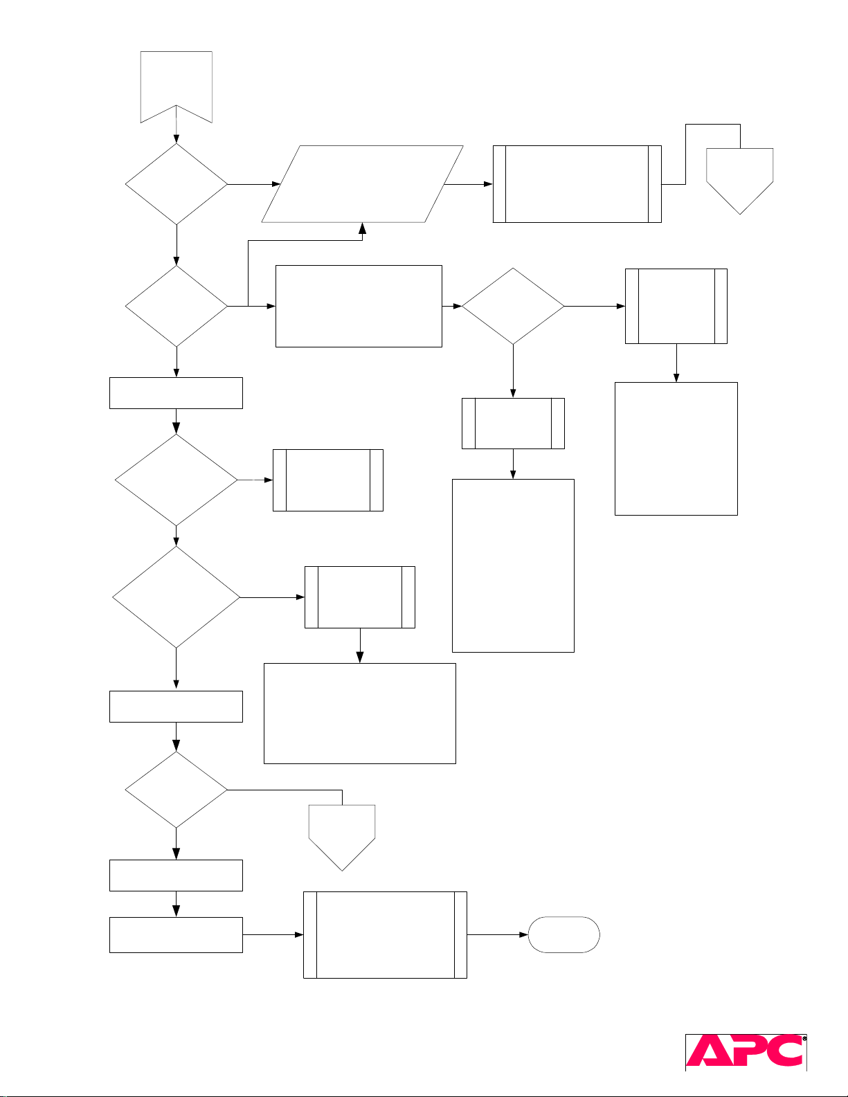
(continued)
Fault
displayed?
No
Does unit
cold start?
Yes
Apply AC input voltage
Does unit go
on-line ?
Yes
Does unit stay on
with all batteries
disconnected?
Yes
Disconnect SNMP
cable from ctrl bd.
Send Y <SM>
Send 1...1 <PROG>
Evaluate CTRL-U
response and LED display.
See "SURT Faults Table"
SURT
Faults
Table
Send CTRL-U
Check PFC:
No
Lynx 2: D716-k to J712: +400V
D715-a to J712: -400V
Lynx 3: PGND to +400V
+/-400V bus
voltages OK?
No
Troubleshoot
PFC
PGND to -400V
Yes
Troubleshoot
Inverter
Lynx2: Check Q708,
Q709, Q710, Q711,
Q726, Q727, D748,
Troubleshoot
No
input voltage
sense and
D749, D723
Lynx3: Check IC903,
IC904
transfer relays
Lynx 2: Check Q705,
Q706, Q715, Q716,
Q717, Q718, D750,
D751
Lynx 3: Check
No
Troubleshoot
Charger
IC1403, IC1404,
IC1407, IC1408
collector-emitter and
gate-emitter
Yes
Lynx 2: Check Q730, Q731, F703,
Re-connect batteries
F704, D736, D737, D738, D739.
Lynx 3: Check Q1407, Q1408,
F1401, F1402, D1406, D1407,
D1408, D1409
Does unit
hold load on
No
battery?
SURT
Yes
Faults
Table
Apply ECO's
Record failure type,
Calibrate and Test unit
list all failed parts along
Done
with part markings
SURT 3kVA – 10kVA Service Manual 19
2005 American Power Conversion. All rights reserved. No part of this publication may be used, reproduced,
photocopied, transmitted, or stored in any retrieval system of any nature, without the written permission of the
Page 20
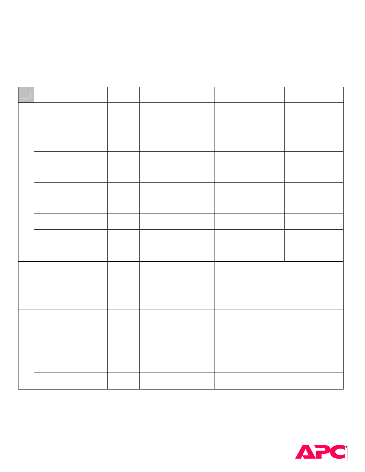
6.5 Diode Checks
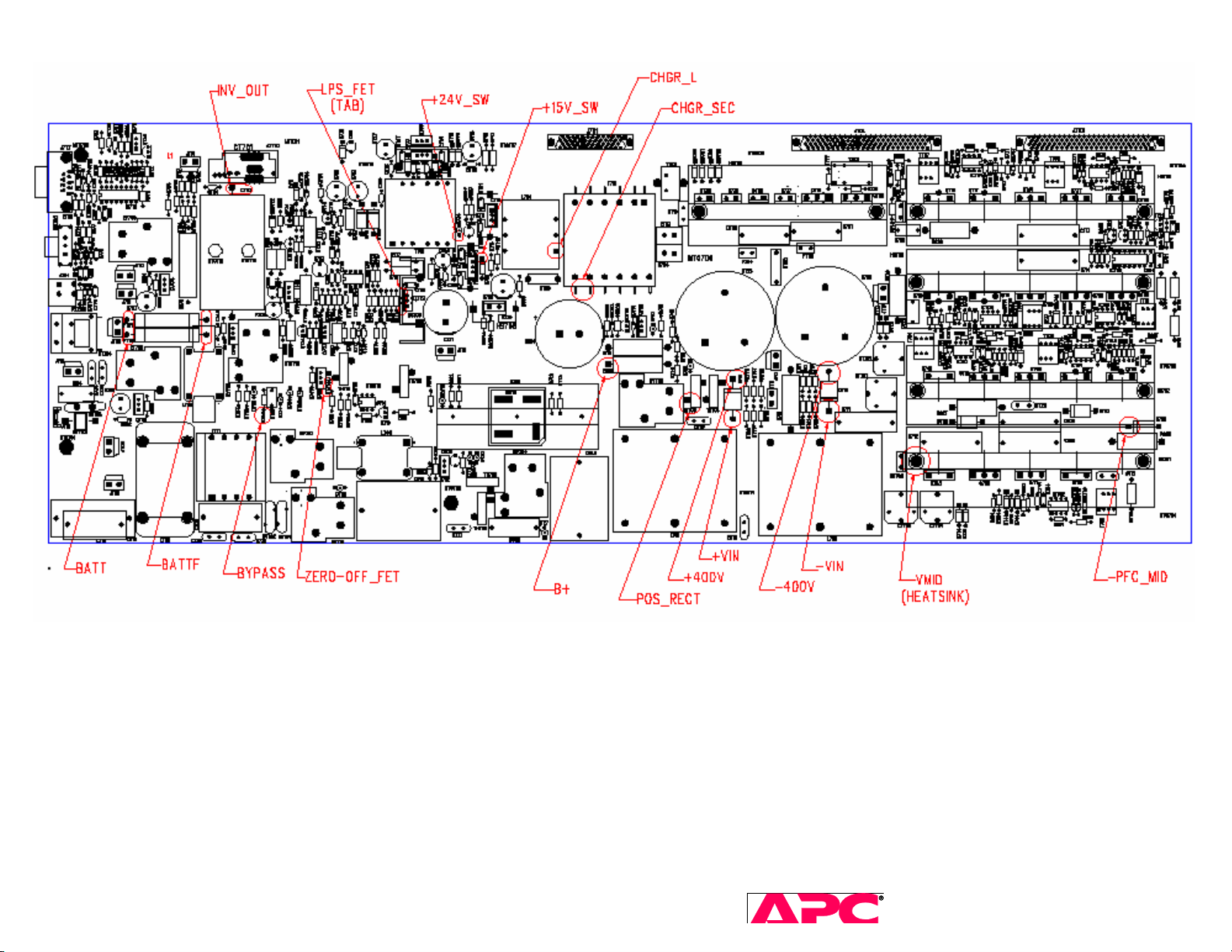
The following “good value” measurements were made with a functional board and a Fluke 87 DMM. These
measurements are approximate and will vary depending on the meter used. See the power board diagram on the
next page for Test Point locations.
Lynx2: 3kVA - 6kVA
+ Probe - Probe
BATT BATTF
Fuse
Good
Value
zero
Components checked
F701, F702 (battery
fuses)
If open If short
Both fuses bad, PFC
probably has problem
OK
+VIN +400V
VMID +VIN
-400V -VIN
PFC
-VIN B+
-VIN VMID
INV_OUT +400V
INV_OUT VMID
VMID INV_OUT
Inverter
-400V INV_OUT
VMID
CHGR_SEC
CHGR_SEC
CHGR_L
0.4V D716, D748 at least 1 part bad
0.45V Q709, Q710, D706 all parts bad at least 1 part bad
0.4V D715, D723 all parts bad at least 1 part bad
0.45V Q726, Q727, D707 all parts bad at least 1 part bad
zero RY704-normally closed RY704 bad OK
0.8V Q706, Q715, Q716 at least 1 part bad
charges
> 2V
charges
> 2V
D751, Q718, Q717
D750, Q715, Q716
if < 2V, Q718 or Q717
bad
if < 2V, Q715 or Q716
bad
0.8V Q705, Q718, Q717 at least 1 part bad
Q706 and
Q715/Q716 bad
At least D751 and 1
IGBT bad
At least D750 and 1
IGBT bad
Q705 and
Q718/Q717 bad
0.45V D738, D739 at least 1 part bad
0.45V D736, D737 at least 1 part bad
CHGR_L BATTF
Charger output
VMID LPS_FET
VMID +24V_SW
Bias Supply
VMID +15V_SW
ZERO-
OFF_FET
ZERO-
Zero off
OFF_FET
B+
BATTF
0.45V D735 D735 bad
0.55V Q712
Q712 bad, check F705, Q729, D714, and
output diodes
0.5V D782 D782 bad, check Q712, F705, Q729, D715
0.5V D781 D781 bad, check Q712, F705, Q729, D714
0.6V D731, TH701, TH702 D731 bad, check TH701, TH702
0.85V Q728 Q728 bad, check MV703, GDT701
SURT 3kVA – 10kVA Service Manual 20
2005 American Power Conversion. All rights reserved. No part of this publication may be used, reproduced,
photocopied, transmitted, or stored in any retrieval system of any nature, without the written permission of the
Page 21
SURT 3kVA – 10kVA Service Manual 21
2005 American Power Conversion. All rights reserved. No part of this publication may be used, reproduced,
photocopied, transmitted, or stored in any retrieval system of any nature, without the written permission of the
copyright owner. www.apc.com Rev 2005-2
Page 22
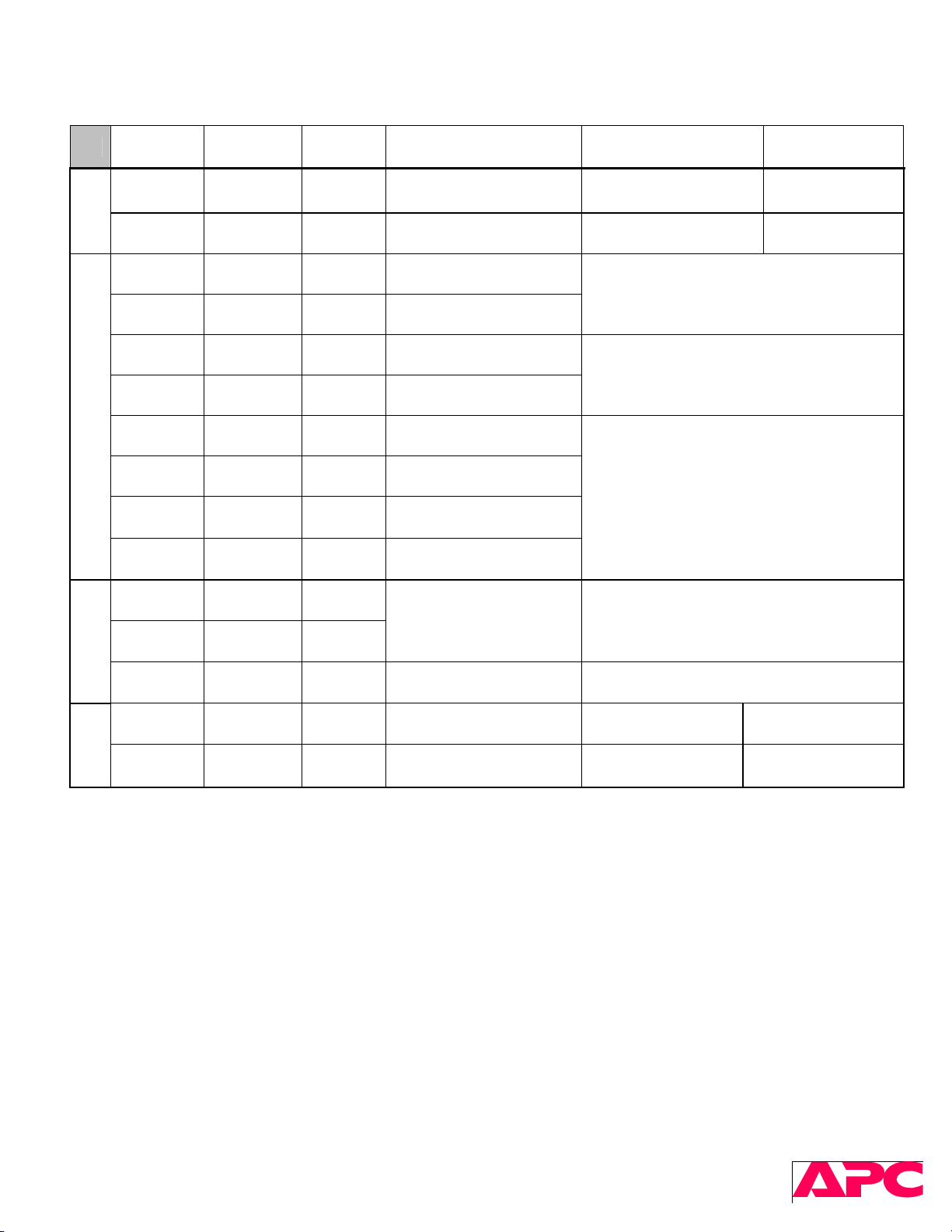
Lynx3: 7.5kVA through 10kVA
+ Probe - Probe
+BATT +BATTF
Fuses
-BATT -BATTF
Good
Value
Components checked
zero F1403, F1404,
zero F1405, F1406
If open If short
Fuses bad, +PFC
probably has problem
Fuses bad, -PFC
probably has problem
OK
OK
+VIN_P1 +400V
+VIN_P2 +400V
-400V -VIN_N1
-400V -VIN_N2
PFC
PGND +VIN_P1
PGND +VIN_P2
-VIN_N1 PGND
-VIN_N2 PGND
-400V INV_OUT
INV_OUT +400V
Inverter
INV_OUT PGND
+Charger
Out
-400V
Charger
+400V
-Charger
Out
0.35V D903, IC903 (at least)
0.35V D905, IC904 (at least)
0.35V D902, IC903 (at least)
0.35V D904, IC904 (at least)
0.4V IC903 (at least)
0.4V IC904 (at least)
0.4V IC903 (at least)
0.4V IC904 (at least)
0.35V
IC1407, IC1408 IC1407 and/or IC1408
0.35V
Open IC1403, IC1404 IC1403 and/or IC1404 bad
0.55V Q1407, F1402
0.55V Q1408, F1401
F1402 open, Q1407
probably bad
F1401 open, Q1408
probably bad
D903, D905,
IC903, and/or IC904 bad
D902, D904,
IC903, and/or IC904 bad
IC903 and/or IC904 bad
Q1407 bad
Q1408 bad
SURT 3kVA – 10kVA Service Manual 22
2005 American Power Conversion. All rights reserved. No part of this publication may be used, reproduced,
photocopied, transmitted, or stored in any retrieval system of any nature, without the written permission of the
copyright owner. www.apc.com Rev 2005-2
Page 23
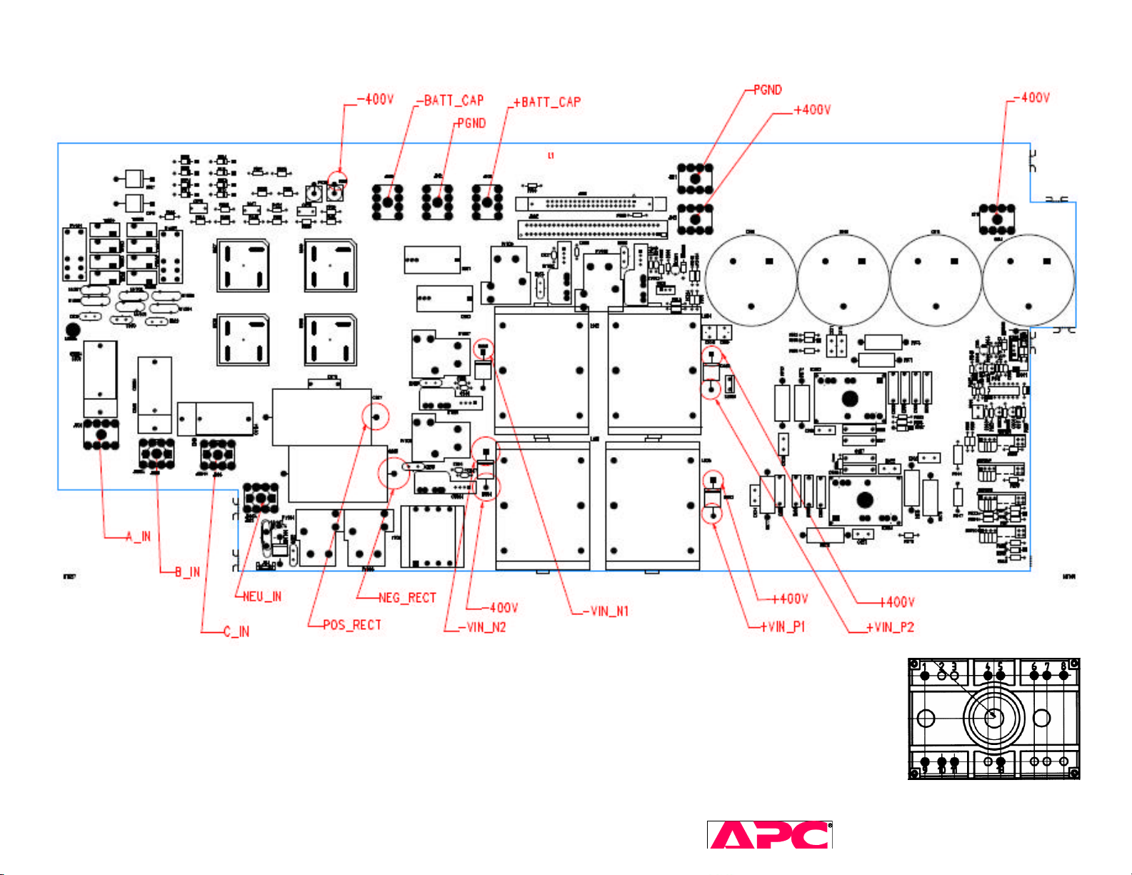
Lynx3 PFC power board, 640-0761
IC903, IC904 =
SURT 3kVA – 10kVA Service Manual 23
2005 American Power Conversion. All rights reserved. No part of this publication may be used, reproduced,
photocopied, transmitted, or stored in any retrieval system of any nature, without the written permission of the
Page 24
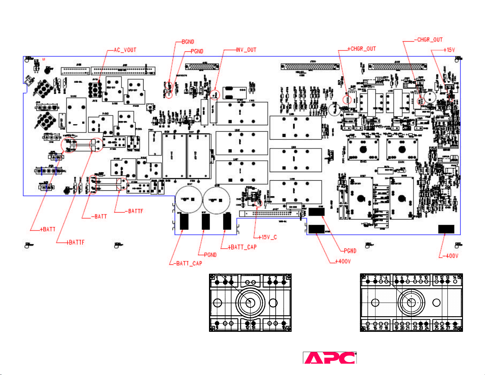
Lynx3 INVERTER power board, 640-0762
IC1403, IC1404 = IC1407, IC408 =.
SURT 3kVA – 10kVA Service Manual 24
2005 American Power Conversion. All rights reserved. No part of this publication may be used, reproduced,
photocopied, transmitted, or stored in any retrieval system of any nature, without the written permission of the
Page 25

Notes:
Cold boot the unit and get the diagnostic information from the serial port before it gets cleared
out. If the unit fails right away, read the display LED pattern and the failure code.
Initial power up (brains up) with batteries only
Check calibration of batteries (both strings), DC buses, firmware version, model #, serial number, etc.
Check fault history (^U command)
Cold-boot
check calibration of DC buses, output AC voltage, etc.
AC-input
check calibration of AC input voltage
disconnect batteries to see if unit shuts down (indicates charger failure)
ON & OFF buttons, BYPASS switch, etc.
Startup with AC-input
Load: add/remove/calibration of watts & VA
AC input: add/remove with load
HF-OFF check
• Bypass switch
• 3phase input switch selection
• Lynx3 Battery voltage commands: ^J for +battery, ^K for –battery in PROG mode
• Once failed part is identified, try to determine if there were any manufacturing defects that might
have caused the part to fail: Insufficient torque on mounting screw, leads not clipped, solder-bridge,
parts touching other components, etc.
• In Terminal Mode, if Model = “??”, the EEPROM has probably become cleared or corrupted.
• “Overload” fault (ctrl-u = 02) is stored during factory testing (during production). Seeing this fault
stored in a field unit does not necessarily mean the overload timeout happened at the customer’s site.
• “EQ charge” is normal in later versions of Lynx2 & Lynx3 firmware. If the battery voltage ever drops
below 200V, the charger will go up to 235V for at least 5 minutes before settling back down to 218V.
EQ charge is also performed about once every 4 weeks.l
6.6 Documenting Failures
Int'l Stars, SIEBEL, or local spreadsheets. Make sure to record all relevant information about the diagnosis:
• Reference designators of failed parts with date codes and vendor marks
• PCB revisions, firmware revisions, accessories added, etc.
• Recommend Corrective Actions and/or PCB revisions as needed.
7 ECO's
See ECO RMA database. For list as of this revision, see Appendix B.
• Need table showing which PCB revision combinations can be used together (examples: 762x requires 763x
or later, 1kVA change)
• Need list of PCB revisions that are ok to ECO and send back to customers
• Need table showing which PCB revisions need which ECO’s
SURT 3kVA – 10kVA Service Manual 25
2005 American Power Conversion. All rights reserved. No part of this publication may be used, reproduced,
photocopied, transmitted, or stored in any retrieval system of any nature, without the written permission of the
copyright owner. www.apc.com Rev 2005-2
Page 26

8 Test After ECO's
(Final test fixture)
All calibration
Cold-boot
AC input: add/remove
Add load, check calibration of Voutput, Wout, VAout, DC buses, Vbatt, ...
AC input: add/remove
With AC input, disconnect batteries
HF-OFF check
SURT 3kVA – 10kVA Service Manual 26
2005 American Power Conversion. All rights reserved. No part of this publication may be used, reproduced,
photocopied, transmitted, or stored in any retrieval system of any nature, without the written permission of the
copyright owner. www.apc.com Rev 2005-2
Page 27
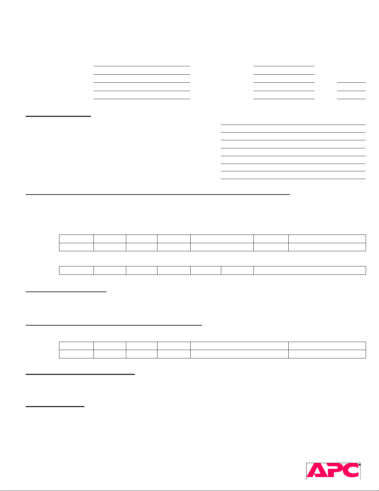
Customer
Customer location RMA date
Report date PCB1 s/n Rev
Model PCB2 s/n Rev
Unit s/n Accessory1 s/n Rev
Initial Assessment
Does the unit cold boot? ___ ___
Does the unit indicate a fault? ___ ___
Does unit operate online with no faults? ___ ___
Is there any output? ___ ___
Does unit switch to bypass? ___ ___
Do all display leds work? ("A" in SM) ___ ___
Does unit operate under 100% load? ___ ___
Unit shut off after 9 min on battery standby? ___ ___
Physical damage (deformed metal or plastic, loose connections, cut insulation, poor crimps, etc.)
Voltages: Pos Bus Neg Bus Vin Vout Charger (no batt) f/w rev Fault History
Command:
Displays
Measured n/a n/a
Voltages 5V 12V -12V -15V 15V 24V Vbat (list packs separately)
Measured
Ctrl G* Ctrl H* Shift L Shift O Shift B or ^J / ^K* b Ctrl U*
Action Taken to Repair
Yes No Additional Information
Repaired Unit - Measured and Calibrated Voltages
Voltages Pos Bus Neg Bus Vin Vout Charger (batteries disconnected) Fault History
Command
Displays
Measured n/a
Ctrl G* Ctrl H* Shift L Shift O Shift B or Shift J / K* (Lynx 3) Ctrl U*
Corrective Actions to be Taken
Additional Notes
*in programming mode
Failure Analysis Report
& Corrective Action Plan
RMA number
2/14/2005
SURT 3kVA – 10kVA Service Manual 27
2005 American Power Conversion. All rights reserved. No part of this publication may be used, reproduced,
photocopied, transmitted, or stored in any retrieval system of any nature, without the written permission of the
copyright owner. www.apc.com Rev 2005-2
Page 28
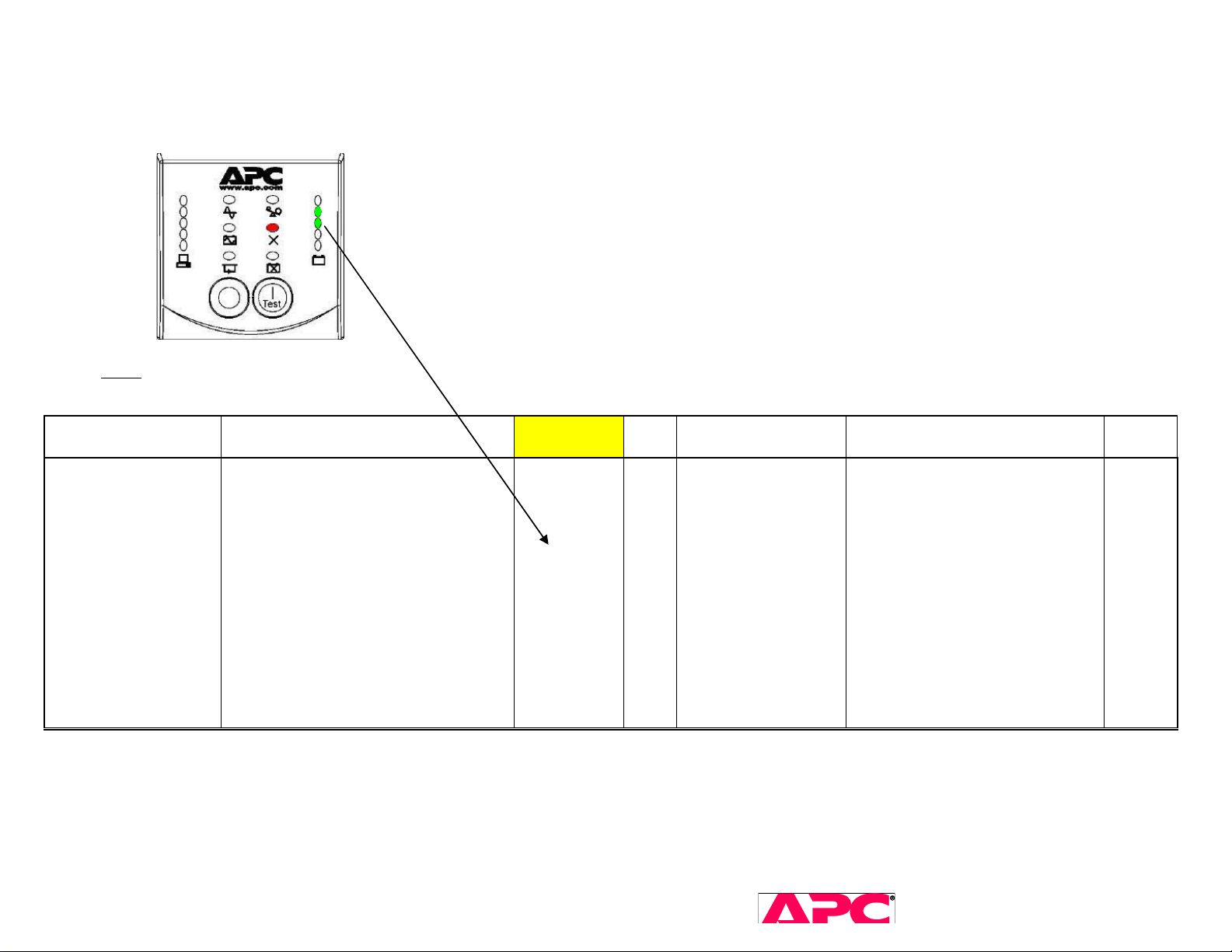
Appendix A. Fault codes on LED display & stored in EEPROM
Display LEDs show "1" for LED ON and "0" for LED OFF in the Battery capacity bar graph. For example, the following display indicates "Battery Capacitor
Soft Start Fault".
Notes
All values provided in UPS-Link terms. Overload test uses % power (watts) or % VA, whichever is greater.
The last fault(s) detected can be retrieved by sending the "Ctrl-U" command in Programming mode.
Fault Action Taken
Battery Capacitor
Soft Start Fault
The unit immediately changes state to
UPS_FAILURE (less than 1ms)
Display
LEDs
0
1
1
0
0
Ctrl-U Auto-Recover from
FAILURE_BYPASS?
11
Can't be in
FAILURE_BYPASS
Repair suggestion
Confirm battery voltage(s) above
165V and that +/-400V buses rise
to within 15V(9V) of the battery
bus(es) within 12 seconds and. If
they don’t, check voltage after softstart PTCs, relay and relay drives.
Lynx2: TH701. TH702, RY702,
Q701, Q728, F701, F702.
Lynx 3: TH1401, TH1402,
TH1403, TH1404, RY1403,
RY1404, RY1405, RY1406,
RY1407, RY1408, Q1402, F1403,
F1404, F1405, F1406
Related
ECOs
BM934
SURT 3kVA – 10kVA Service Manual 28
2005 American Power Conversion. All rights reserved. No part of this publication may be used, reproduced,
photocopied, transmitted, or stored in any retrieval system of any nature, without the written permission of the
copyright owner. www.apc.com Rev 2005-2
Page 29
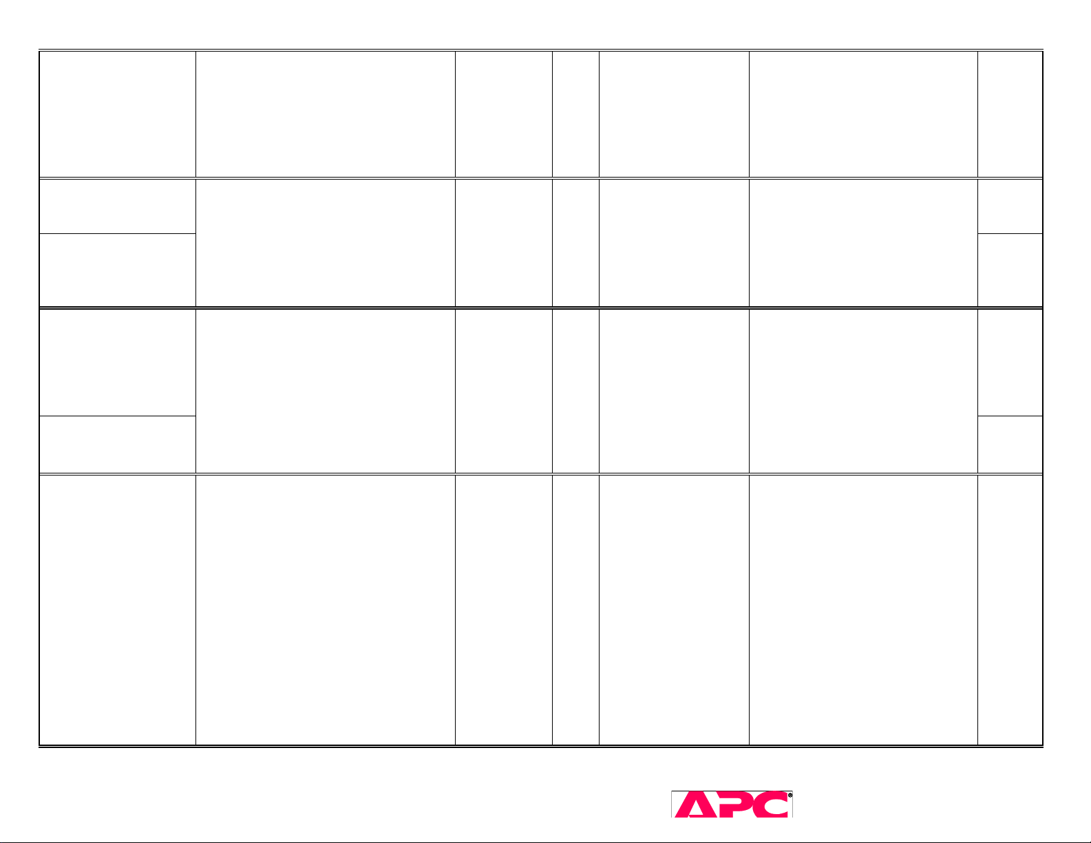
Battery <-> Line
(PFC Input) Relay
Weld fault
Bypass Relay Fault
(Bypass relay is
closed)
Bypass Relay Fault
(Output is off)
Battery Charger
Fault(descent method)
Battery Charger Fault
(hard limit)
No immediate action taken. State
change will take place in the next AC
line cycle (9ms @50Hz or 7ms @60Hz)
The UPS will transfer to
FAILURE_BYPASS or UPS_FAILURE
state (See State Diagram.)
No immediate action is taken. Unit will
change the state to UPS_FAILURE a
half of an AC cycle later (10ms @ 50Hz
or 8ms @ 60Hz)
No immediate action taken. State
change will take place in the next AC
line cycle (13.3ms @50Hz or 11.1ms
@60Hz) The UPS will transfer to
FAILURE_BYPASS or UPS_FAILURE
state (See State Diagram.)
1
0
0
0
1
0
1
0
0
1
0
1
0
1
0
0D
0F
12
NO
Can't be in
FAILURE_BYPASS
NO
Lynx3:
Confirm customer wiring to
input terminal block (hardwired).
Input wires might be connected
to Output terminal block by
mistake.
Check Bypass contactor and drive
Lynx 2:
Check Q727, Q728, F703, F704,
D736, D737, D738, D739, Q730,
Q731
Lynx 3:
Check Q1407, Q1408, F1401,
F1402, D1406, D1407, D1408,
D1409
DC Bus Overvoltage Fault will
immediately turn-off the Inverter in
hardware. The PFC will be turned off
upon detection of this fault.
Case 1 (Inverter relay is closed): The
Inverter will be commanded off and new
DC Bus Overvoltage
Fault
state will be set: UPS_FAILURE or
FAILURE_BYPASS. Should UPS
transfer to FAILURE_BYPASS, output
Relay will be commanded to open and
Bypass Relay will be commanded to
0
1
0
0
0
08
close immediately.
Case 2 (Inverter relay is open): UPS
will transfer to UPS_FAILURE state at
the closest AC line phase angle of 67.5
degrees (or in less than 18msec
@50Hz or 15msec @60Hz.)
SURT 3kVA – 10kVA Service Manual 29
2005 American Power Conversion. All rights reserved. No part of this publication may be used, reproduced,
photocopied, transmitted, or stored in any retrieval system of any nature, without the written permission of the
copyright owner. www.apc.com Rev 2005-2
YES
Page 30
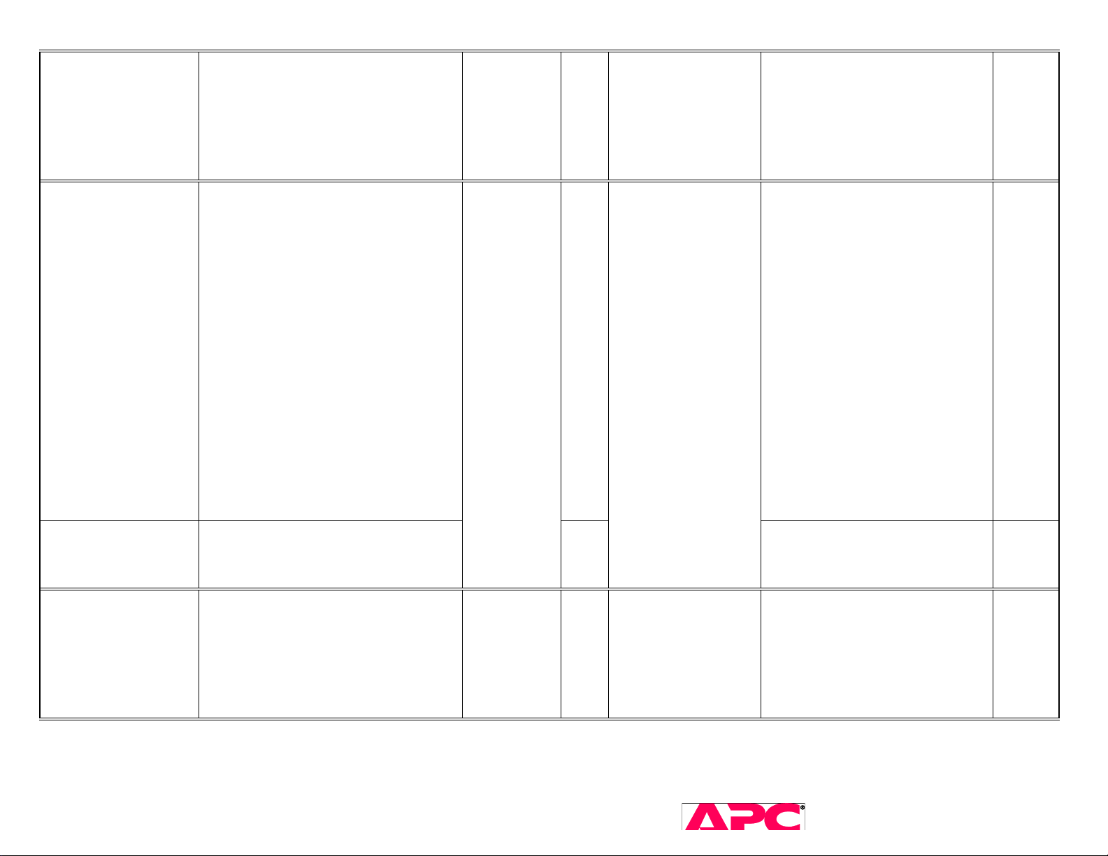
Fan Fault
Inverter Fault
(Hardware fault)
Inverter Fault
(Output voltage test)
State transitions in the next AC line
cycle (4ms @50Hz 3ms @60Hz)
Note: The UPS still tries to control the
high/low speed mode selection for the
fan.
The UPS commands an immediate turn
off of the Inverter, the PFC and the
Charger. Next, the unit will enter either
a FAILURE_BYPASS or
UPS_FAILURE state (See State
Diagram.) Upon setting the
FAILURE_BYPASS state the UPS will
command the Bypass and the Backfeed
relays to close. Upon setting
UPS_FAILURE state the UPS will
command the Bypass and Backfeed
relays to open. For either state the unit
commands the Output Relay to
open.Note: Normal UPS_FAILURE/
FAILURE_BYPASS procedure timings
can not be applied in this case. The rest
of hardware control operations (e.g.
PFC input relay control) will take place
in the next AC line cycle. So, the
timings specified will start from phase
angle 0.
No immediate action is taken. All state
transitions are taking place in the next
AC cycle. (20msec @50Hz, 17msec
@60Hz)
0
0
1
1
0
0
0
0
0
1
10
06
0B
YES
NO
Check: Fan connections to control
board (Lynx2 uses J5 only), fan
guard is not pushed in, no foreign
objects stuck in fan blades, fan
frame not broken
Lynx 2: Check Q705, Q706, Q715,
Q716, Q717, Q718, D750, D751
Lynx 3: Check IC1403, IC1404,
IC1407, IC1408 collector-emitter
and gate-emitter
Same as above
1
Logic Power Supply
Fault
Immediately switches in UPS_FAILURE
state. (See Normal Behavior for
UPS_FAILURE State.)
1
0
0
01
FAILURE_BYPASS
0
SURT 3kVA – 10kVA Service Manual 30
2005 American Power Conversion. All rights reserved. No part of this publication may be used, reproduced,
photocopied, transmitted, or stored in any retrieval system of any nature, without the written permission of the
copyright owner. www.apc.com Rev 2005-2
Can't be in
R544, R545 should be 10k TA107
Page 31
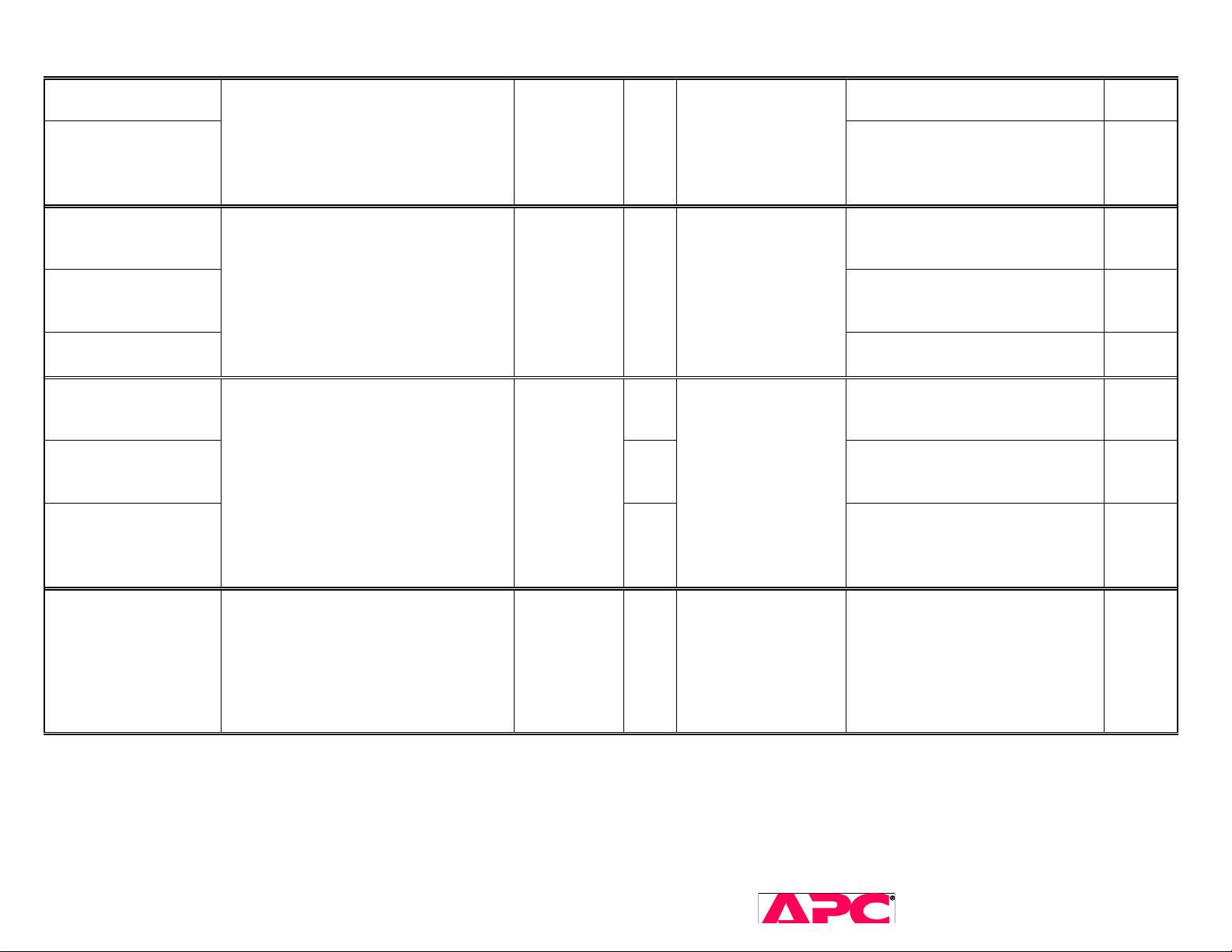
High Output Voltage
High Output Voltage
(Extreme Overvoltage)
No immediate action is taken. The UPS
will transfer to UPS_FAILURE or
FAILURE_BYPASS state (see State
Diagram) in the next AC line cycle.
(19msec @50Hz or 16ms @60Hz)
0
0
0
1
1
09
NO
Output Relay Fault
(bypass relay is
closed)
Output Relay Fault
(Transferring
to inverter-on state)
Output Relay Fault
(Inverter is on)
Overload (Percent
LoadInverter is on)
Overload
(Low output voltage)
Overload
(Percent Load
Bypass Relay is
No immediate action is taken. The UPS
will transfer into UPS_FAILURE state in
the next AC cycle (8ms @50Hz or 6ms
@60Hz.)
No immediate action is taken. All state
transitions are taking place in the next
AC cycle (19msec @ 50Hz or 16msec
@60Hz.)The UPS will sound the
beeper as long as the fault conditions
are present.
0
0
1
0
1
Overload
LED
0E
02
05
03
Can't be in
FAILURE_BYPASS
YES
This fault is stored in ‘Ctrl-U’
during factory testing. It is not
cleared before shipment.
closed)
Overtemperature
No immediate action is taken. All state
transitions are taking place in the next
AC cycle (4msec @50Hz or 3msec
@60Hz.) The UPS will transfer to
FAILURE_BYPASS or UPS_FAILURE
(see State Diagram.)
1
0
0
0
0
07
SURT 3kVA – 10kVA Service Manual 31
2005 American Power Conversion. All rights reserved. No part of this publication may be used, reproduced,
photocopied, transmitted, or stored in any retrieval system of any nature, without the written permission of the
copyright owner. www.apc.com Rev 2005-2
YES
Page 32
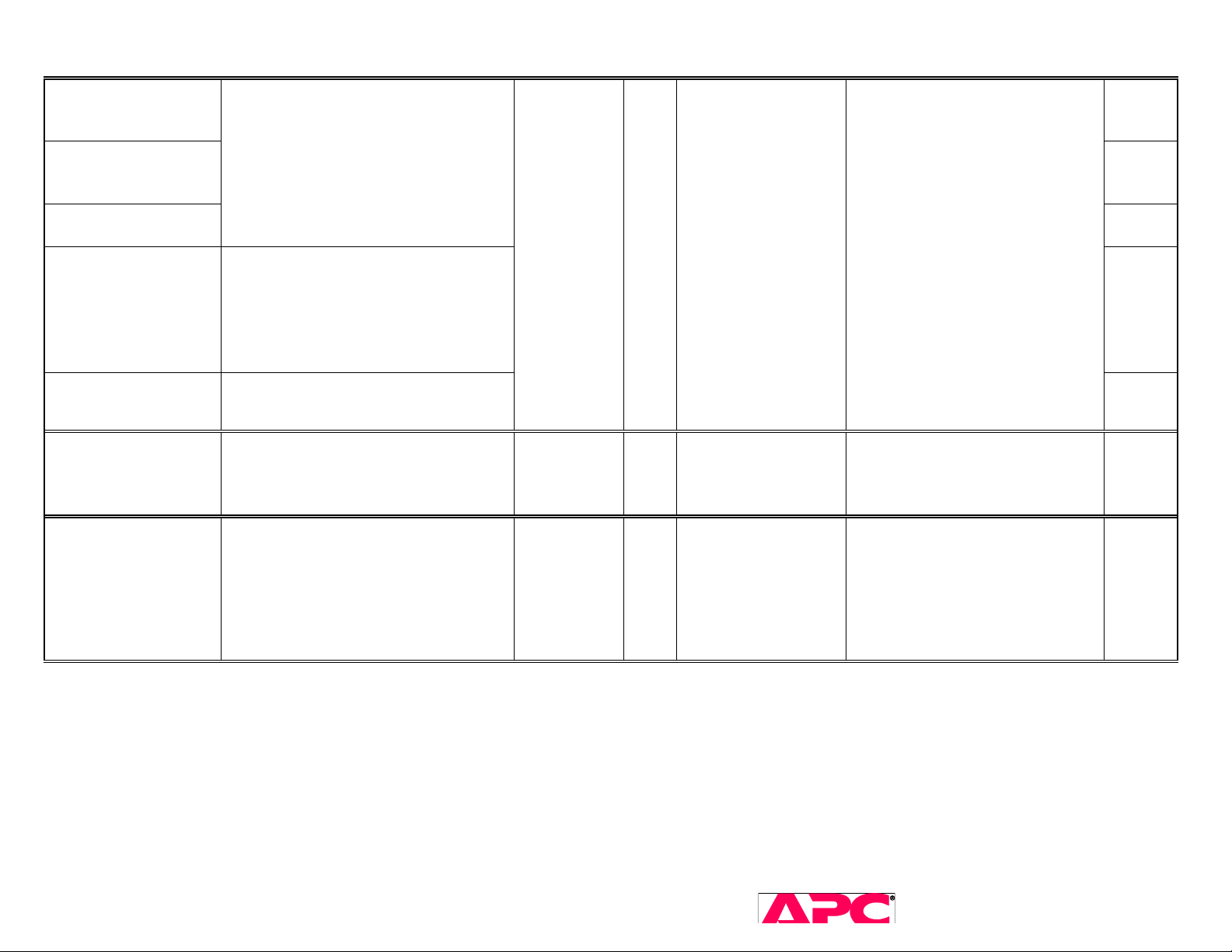
PFC Failure
(Inverter on,
hard limit detection)
PFC Failure
(Inverter on,
delta detection)
PFC Failure
(Inverter off)
PFC Failure
(Charging up DC
Buses)
PFC Failure
(cold-boot)
No immediate action is taken. The UPS
will transfer to FAILURE_BYPASS or
UPS_FAILURE state (see State
Diagram.) State transitions will take
place at the closest phase angle of 67.5
degrees of AC line cycle.
Upon detection of this fault, the PFC is
turned off immediately, state transitions
are taking place in the next AC cycle
(8msec @50Hz or 6msec @60Hz.) The
UPS will transfer into
FAILURE_BYPASS or UPS_FAILURE
state (see State Diagram.)
Upon detection of this fault, the UPS
will immediately enter UPS_FAILURE
state.
0
0
1
0
0
Lynx2:
Q708, Q709, Q710, Q711, Q726,
Q727, D748, D749, D723, DC bus
and battery voltage feedback
0A
YES
resistors, esp. R856, R857
Lynx3:
IC903, IC904, DC bus and battery
voltage feedback resistors
Short Circuit Same as overload above.
No immediate action is taken. All state
transitions are taking place in the next
Backfeed Relay Weld
AC cycle. (8msec @50Hz or 6msec
@60Hz) The UPS will transfer to
FAILURE_BYPASS or UPS_FAILURE
(see State Diagram.)
Overload
LED
0
0
0
1
0
04
0C
FAILURE_BYPASS
SURT 3kVA – 10kVA Service Manual 32
2005 American Power Conversion. All rights reserved. No part of this publication may be used, reproduced,
photocopied, transmitted, or stored in any retrieval system of any nature, without the written permission of the
copyright owner. www.apc.com Rev 2005-2
Can't be in
NO
Page 33
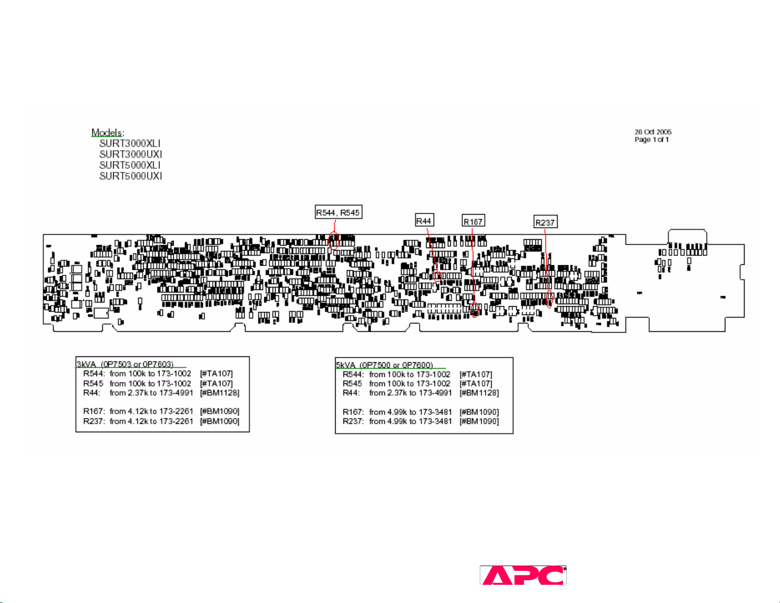
Appendix B. ECO list as of October, 2005
Lynx2 modifications (Control board) – mirrored 180 degrees
SURT 3kVA – 10kVA Service Manual 33
2005 American Power Conversion. All rights reserved. No part of this publication may be used, reproduced,
photocopied, transmitted, or stored in any retrieval system of any nature, without the written permission of the
copyright owner. www.apc.com Rev 2005-2
Page 34
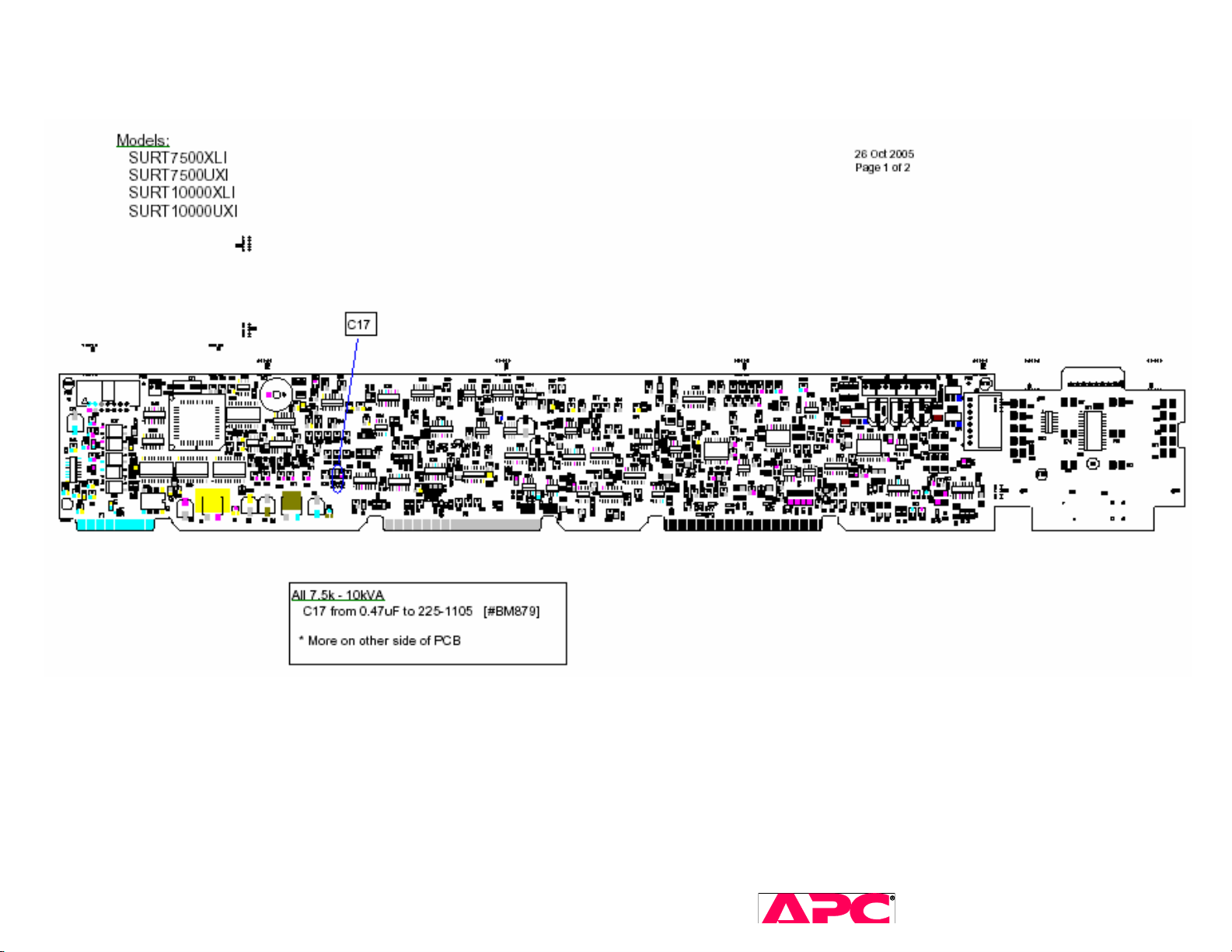
Lynx3 modifications (Control board, top side)
SURT 3kVA – 10kVA Service Manual 34
2005 American Power Conversion. All rights reserved. No part of this publication may be used, reproduced,
photocopied, transmitted, or stored in any retrieval system of any nature, without the written permission of the
copyright owner. www.apc.com Rev 2005-2
Page 35
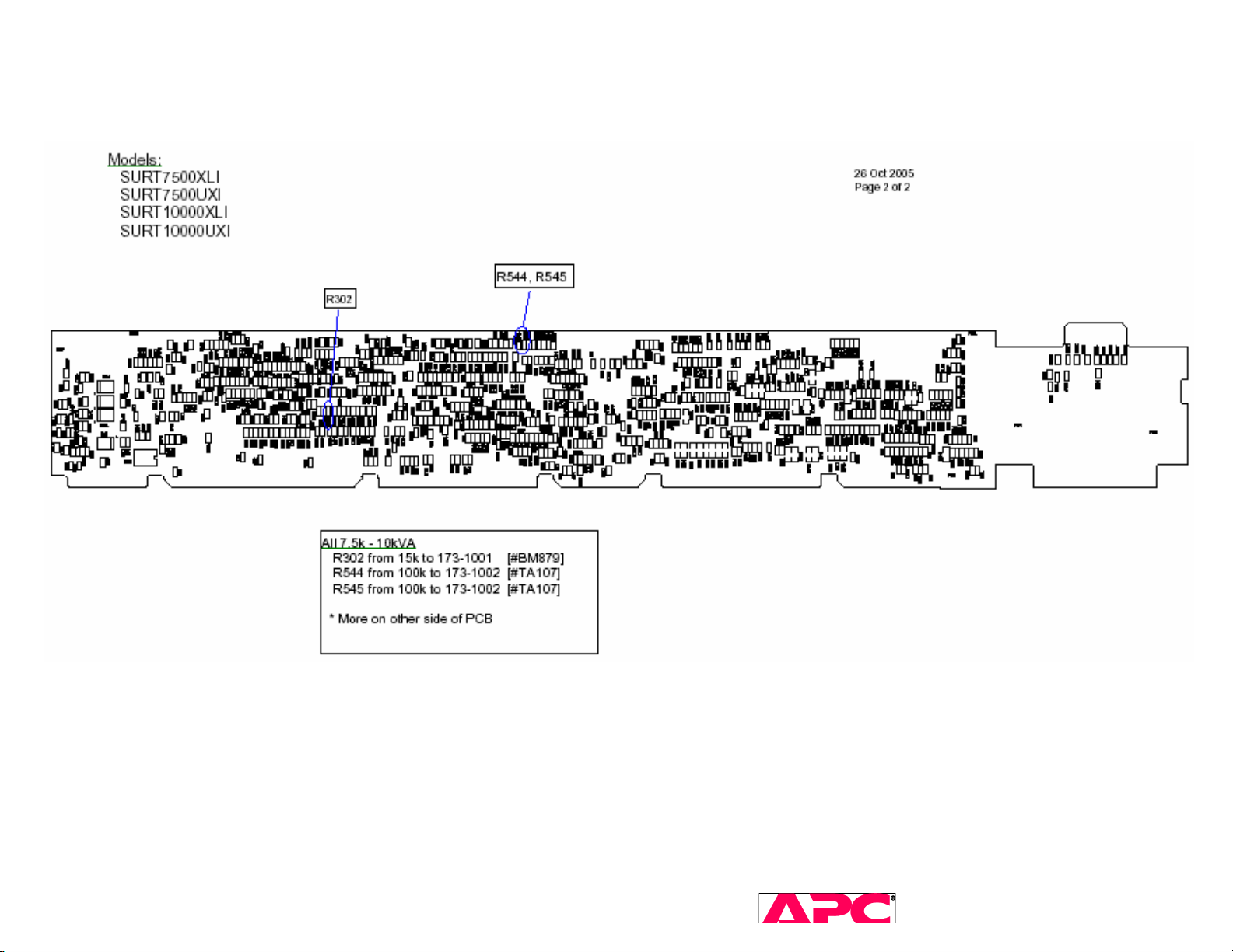
Lynx3 modifications continued (Control board, bottom side) – mirrored 180 degrees
SURT 3kVA – 10kVA Service Manual 35
2005 American Power Conversion. All rights reserved. No part of this publication may be used, reproduced,
photocopied, transmitted, or stored in any retrieval system of any nature, without the written permission of the
copyright owner. www.apc.com Rev 2005-2
 Loading...