

Page 1
PDU Branch Current Monitoring Board
d
Installation and Configuration
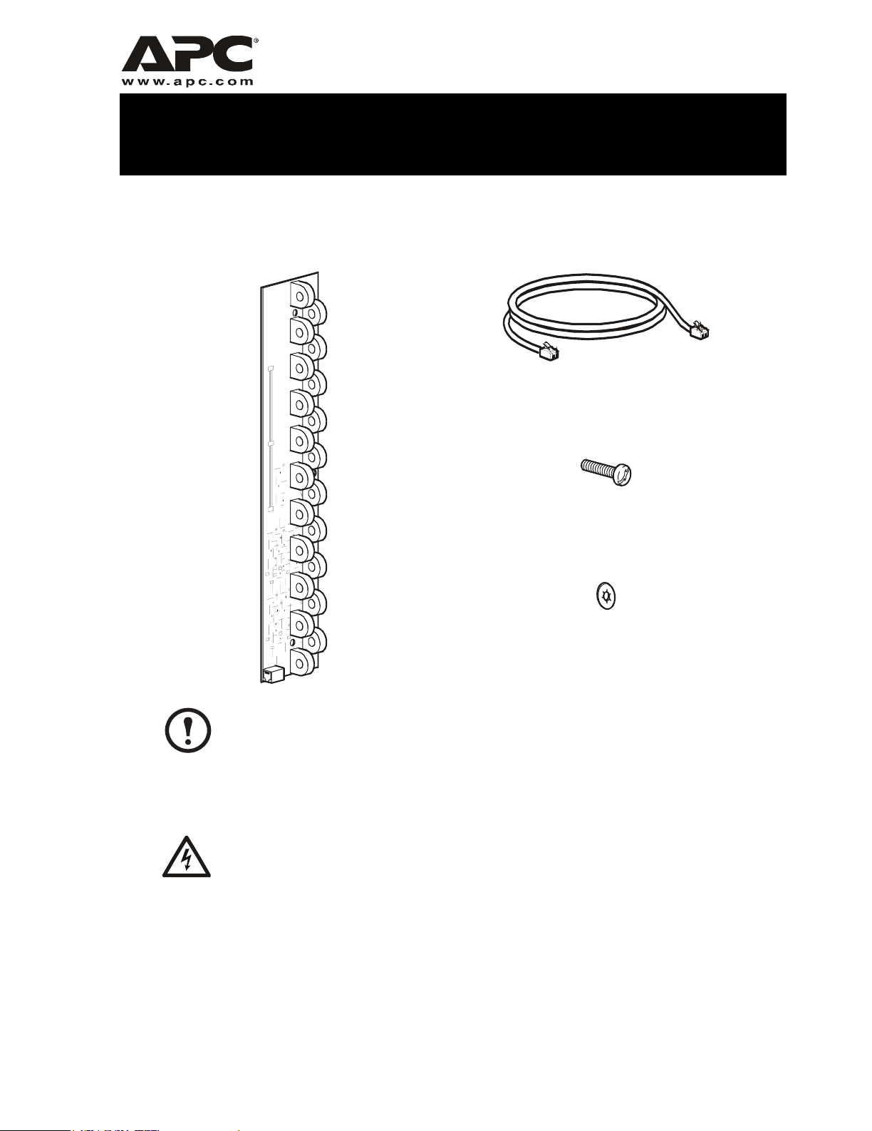
Inventory
(1) (1)
(3)
The branch current monitoring board can be installed only in a PDU with a serial
number of XF0314 or higher.
Note
Safety
Before installing the branch current monitoring board, ensure that your system is
Electrical
Hazar
Mounting the board in the PDU
not receiving power (Total Power Off).
(3)
The branch current monitoring board mounts to brackets in the PDU on the right and left side of each
circuit breaker panel. The illustration in step 2 on page 2 shows the mounting brackets on the upper
right-hand side of the PDU circuit breaker panel.
Page 2
Installation and Configuration
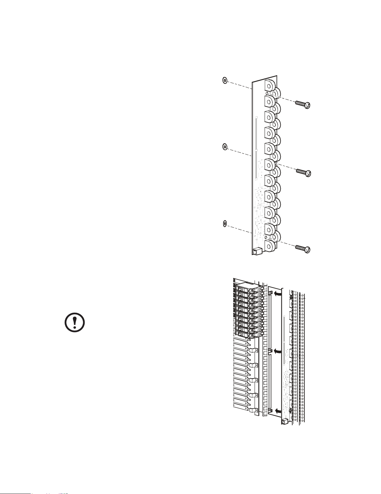
Installation
How to mount the board in the PDU.
1. Insert the three socket-head screws into the
board and attach the retainers to the screws.
2. Attach the board to any of the four sets of
mounting brackets inside the PDU.
The front of the board must face away
from the PDU.
Note
3. Secure the board to the mounting brackets with a
5-mm Allen wrench, and torque 14– 16 in-lb
(1.7N-m).
2 Branch Current Monitoring Kit
Page 3

Installation and Configuration
How to route power cable wires.
1. Route the phase conductor through a current sensor. If it is a three-phase cable, route each of the
L1, L2, and L3 wires through its own current sensor.
2. Connect the L1, L2, and L3 wires to single-pole breakers or to a three-pole breaker. (The
illustration below shows single-pole breakers.)
3. Connect the neutral wire (!) to the closest open termination point on the Neutral Bar.
4. Connect the ground wire (") to the closest open termination point on the Ground Bar.
!
"
Branch Current Monitoring Kit 3
Page 4

Installation and Configuration
How to connect the board to the monitoring unit.
1. Plug one end of the monitoring cable into the port on the board.
If the board is on the left side of the PDU, the port will be on the bottom of the
board. If the board is on the right side of the PDU, the port will be on the top.
Note
2. Plug the other end of the cable into a port on the PDU monitoring unit.
There are four available ports on the PDU monitoring unit to accommodate up to
four boards. The ports are labeled according to their circuit breaker assignments.
Note
The following illustration shows the location of the ports on the PDU monitoring
unit and the label describing the circuit breakers assigned to each port.
Location of Board Circuit Breaker Numbers
Upper-left side of PDU 01...41
Upper-right side of PDU 02...42
Lower-left side of PDU 43...83
Lower-right side of PDU 44...84
4 Branch Current Monitoring Kit
Page 5

Installation and Configuration
Configuration
Configure the branch current monitoring parameters using either the Panel configuration option or
Global panel config option on the Panel screen of the PDU display interface.
Panel Config. Configure the branch metering settings for each
circuit breaker on the distribution panel, or configure both panels
simultaneously.
To configure a circuit breaker, select the range
Panel Configuration
Select Range:
[01..41] [02..42]
that includes the circuit breaker. The top line of selections on the
screen applies to the top distribution circuit breaker panel on the PDU. The bottom line of selections
applies to the bottom distribution circuit breaker panel on the PDU. The panel position numbers on
the screen correspond to the numbers on the distribution panel. Odd numbers are on the left; even
numbers are on the right. Once you have selected the correct range, configure the settings for each
circuit breaker in the range.
Pos: The panel positions in the selected range.
Breaker: There are two configurable items:
• The circuit breaker rating, in amps
• The circuit breaker tie indicator: Define the number of tied panel positions (i.e., associated).
You can associate panel positions with circuit breakers, to view the status about each circuit
breaker and to receive alarm notification when any of a circuit breaker’s poles are above or
below the configured branch circuit limit. You can also tie together panel positions that are
logically associated. For example, you can tie together panel positions for three separate circuit
breakers that are connected to the same PDU power cord and that provide power to the same
equipment enclosure.
To configure the values on this screen:
1. From the first column, use the arrow keys to scroll up or down to the pole position you want to
configure.
2. Press the
ENTER key to move to the item you want to configure in the third column (the circuit
breaker rating or the circuit breaker tie indicator).
3. Scroll again to select the value you want for the circuit breaker rating or the circuit breaker tie
indicator. To associate one panel position with the next position in the list, choose the
+
character as the tie indicator immediately following the circuit breaker rating. To indicate that
the position is not associated with (tied to) the next panel position in the list, choose the
]
character as the tie indicator immediately following the circuit breaker rating. When you change
the
+ or ] character that follows the circuit breaker rating in one row, the + or [ character before
the circuit breaker rating in the next row also changes to indicate the changed association
between the panel positions.
For example, this screen shows three, single-pole, 20A, tied
circuit breakers occupying positions 08, 10, and 12 on the
top right distribution panel.
Pos
08
10
12
Breaker
[ 20A +
+ 20A +
+ 20A ]
Branch Current Monitoring Kit 5
Page 6

Installation and Configuration
Global Panel Config. Configures the same number of poles or circuit breaker ratings for all circuit
breakers in both distribution panels simultaneously. For example, if your system uses only three-pole,
20-amp circuit breakers, choose this option, scroll to the value 3 for Poles and 020 for Amp Rating.
Select Apply Now and YES to implement your changes.
Specifications
Branch Monitor Parameters Maximum current (RMS): 95A
Maximum current (peak): 135A
Maximum crest factor: 3
Minimum current: 0.5A
Measurement accuracy: +/- 0.5A or 5% of reading
(whichever is greater)
Maximum wire size: 0.35in (8.89mm) maximum diameter
InfraStruXure System Parameters Branch circuit range: 20–60A
Maximum scan (refresh) time: 3 seconds
Display resolution: 0.1A
6 Branch Current Monitoring Kit
Page 7

Page 8

APC Worldwide Customer Support
Customer support for this or any other APC product is available at no charge in any of the following ways:
• Visit the APC Web site to access documents in the APC Knowledge Base and to submit customer support
requests.
– www.apc.com (Corporate Headquarters)
Connect to localized APC Web sites for specific countries, each of which provides customer support
information.
– www.apc.com/support/
Global support searching APC Knowledge Base and using e-support.
• Contact an APC Customer Support center by telephone or e-mail.
– Regional centers:
Direct InfraStruXure Customer Support
APC headquarters U.S., Canada (1)(800)800-4272 (toll free)
Latin America (1)(401)789-5735 (USA)
Europe, Middle East, Africa (353)(91)702055 (Ireland)
Japan (0) 35434-2021
Australia, New Zealand, South Pacífic (61) (2) 9955 9366 (Australia)
– Local, country-specific centers: go to www.apc.com/support/contact for contact information.
Contact the
how to obtain local customer support.
APC representative or other distributor from whom you purchased your APC product for information on
Entire contents copyright © 2004 American Power Conversion. All rights reserved.
Reproduction in whole or in part without permission is prohibited. APC, the APC logo, and
InfraStruXure are trademarks of American Power Conversion Corporation and may be registered
in some jurisdictions. All other trademarks, product names, and corporate names are the property
of their respective owners and are used for informational purposes only.
fif(1)(877)537-0607 (toll free)
990-1646A 08/2004
*990-1646A*
 Loading...