

Page 1

Installation and
Quick Start
Automatic Transfer
Switch
Page 2

This manual is available in English on the enclosed CD.
Dieses Handbuch ist in Deutsch auf der beiliegenden CD-ROM verfügbar.
Este manual está disponible en español en el CD-ROM adjunto.
Ce manuel est disponible en français sur le CD-ROM ci-inclus.
Questo manuale è disponibile in italiano nel CD-ROM allegato.
本マニュアルの日本語版は同梱の CD-ROM からご覧になれます。
Instrukcja Obs
O manual em Português está disponível no CD-ROM em anexo.
Данное руководство на русском языке имеется на прилагаемом компакт-диске.
Bu kullanim kilavuzunun Türkçe'sä, äläxäkte gönderälen CD äçeräsände mevcuttur.
您可以从包含的 CD 上获得本手册的中文版本。
ługi w jezyku polskim jest dostepna na CD.
Page 3

Contents
Preliminary Information . . . . . . . . . . . . . . . . . . . . . . . . . . . . . . . . . . . .1
Additional documentation . . . . . . . . . . . . . . . . . . . . . . . . . . 1
Please recycle . . . . . . . . . . . . . . . . . . . . . . . . . . . . . . . . . . 1
Receiving inspection . . . . . . . . . . . . . . . . . . . . . . . . . . . . . 1
Product inventory . . . . . . . . . . . . . . . . . . . . . . . . . . . . . . . 2
Overview. . . . . . . . . . . . . . . . . . . . . . . . . . . . . . . . . . . . . . . . . . . . . . . . .3
Front panel . . . . . . . . . . . . . . . . . . . . . . . . . . . . . . . . . . . . 3
Installation . . . . . . . . . . . . . . . . . . . . . . . . . . . . . . . . . . . . . . . . . . . . . . .4
Attach mounting brackets . . . . . . . . . . . . . . . . . . . . . . . . . . 4
Disassemble the adjustable brackets . . . . . . . . . . . . . . . . . . 4
Attach rear segments to the rack . . . . . . . . . . . . . . . . . . . . . 5
Attach front segments to the switch . . . . . . . . . . . . . . . . . . . 5
Mount the Automatic Transfer Switch in the enclosure . . . . . . . 6
Quick Configuration . . . . . . . . . . . . . . . . . . . . . . . . . . . . . . . . . . . . . . .7
Overview . . . . . . . . . . . . . . . . . . . . . . . . . . . . . . . . . . . . . 7
TCP/IP configuration methods . . . . . . . . . . . . . . . . . . . . . . . 7
Device IP Configuration Wizard . . . . . . . . . . . . . . . . . . . . . . 8
BOOTP & DHCP configuration . . . . . . . . . . . . . . . . . . . . . . . 8
Local access to the control console . . . . . . . . . . . . . . . . . . 10
How to Access the Automatic Transfer Switch Interfaces . . . . . . .11
Overview . . . . . . . . . . . . . . . . . . . . . . . . . . . . . . . . . . . . 11
Web interface . . . . . . . . . . . . . . . . . . . . . . . . . . . . . . . . . 11
Telnet/SSH . . . . . . . . . . . . . . . . . . . . . . . . . . . . . . . . . . . 12
SNMP . . . . . . . . . . . . . . . . . . . . . . . . . . . . . . . . . . . . . . 12
FTP/SCP . . . . . . . . . . . . . . . . . . . . . . . . . . . . . . . . . . . . 13
Configuring the ATS . . . . . . . . . . . . . . . . . . . . . . . . . . . . . . . . . . . . . .14
Configuring sensitivity . . . . . . . . . . . . . . . . . . . . . . . . . . . 14
Configuring voltage transfer range . . . . . . . . . . . . . . . . . . . 14
Remote access to the control console . . . . . . . . . . . . . . . . . 15
Recovering From A Lost Password. . . . . . . . . . . . . . . . . . . . . . . . . .16
Warranty. . . . . . . . . . . . . . . . . . . . . . . . . . . . . . . . . . . . . . . . . . . . . . . .17
Life-Support Policy . . . . . . . . . . . . . . . . . . . . . . . . . . . . . . . . . . . . . . .19
Automatic Transfer Switch — Installation and Quick Start i
Page 4

Page 5

Preliminary Information
Additional documentation
This Installation and Quick Start Manual and the online User’s Guide are available on the supplied
CD or on the American Power Conversion (APC
contains additional information about the following topics related to the Automatic Transfer Switch:
• Management interfaces
• User accounts
• Customizing setup
•Security
Please recycle
The shipping materials are recyclable. Please save them for later use, or dispose of
them appropriately.
®
) Web site www.apc.com. The online User’s Guide
Receiving inspection
Inspect the package and contents for shipping damage, and make sure that all parts were sent. Report
any shipping damage immediately to the shipping agent, and report missing contents, damage, or
other problems immediately to APC or your APC reseller.
Automatic Transfer Switch - Installation and Quick Start 1
Page 6
Preliminary Information
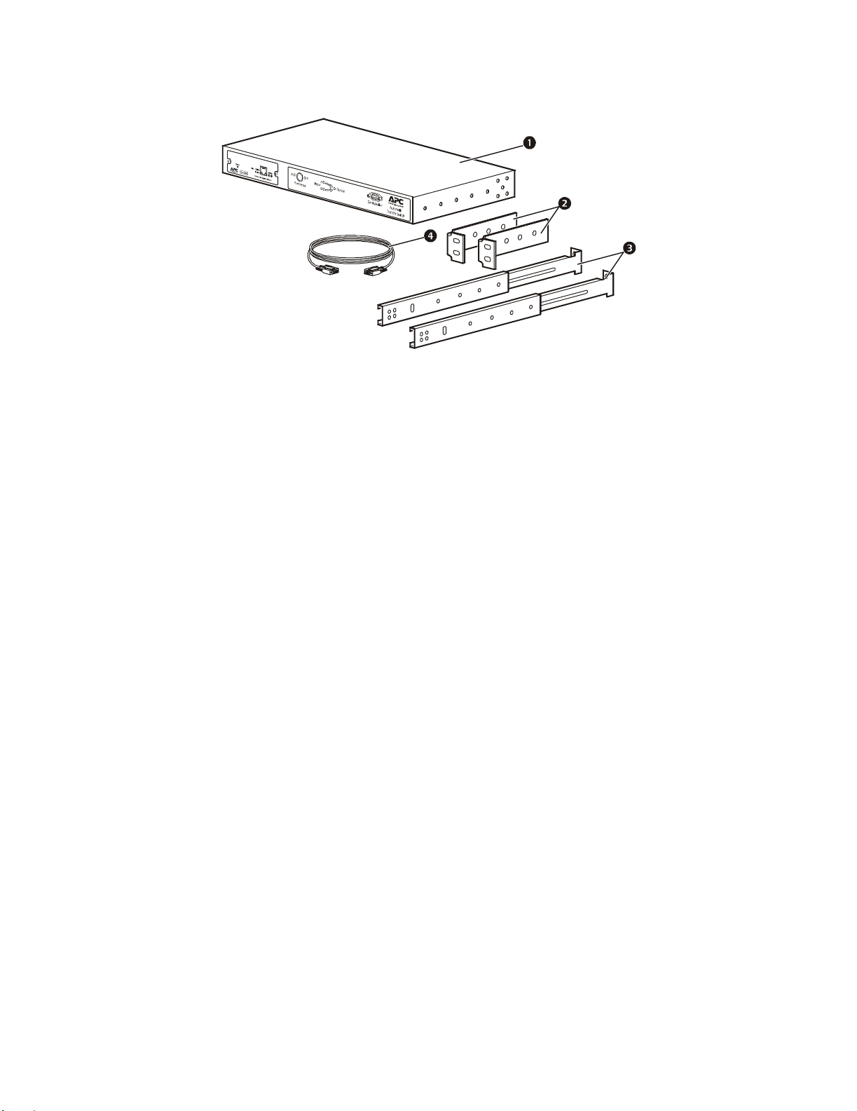
Product inventory
Automatic Transfer Switch
Rack-mount brackets
Front and rear rail segments
mph0080a
Communication cable
2 Automatic Transfer Switch - Installation and Quick Start
Page 7
Overview
A
A
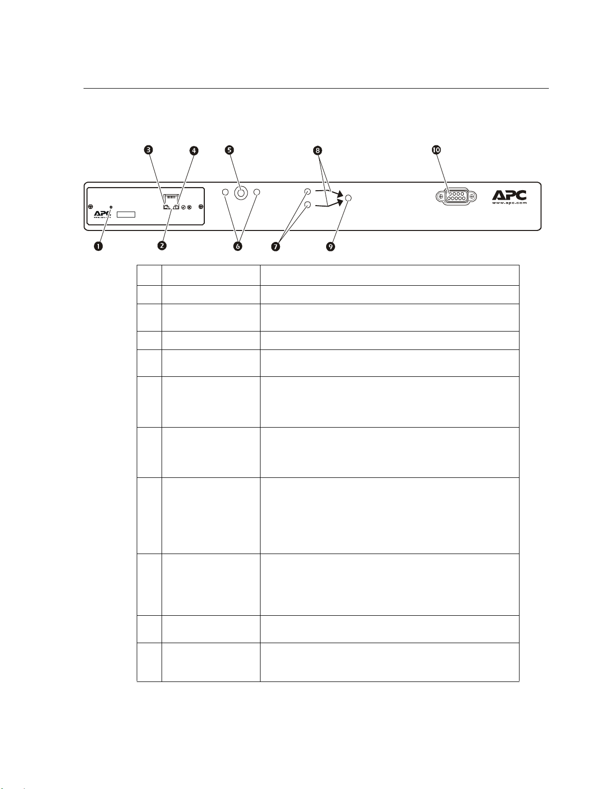
Front panel
Reset
Sma rt Sl ot
Link - RX/TX Status
10/100
Network Management Card
AB
Preference
Input
B
No. Item Description/Function
Reset switch Restarts the Network Management Card.
Ethernet port Connects the Automatic Transfer Switch to your network,
using a network cable.
Link–RX/TX LED Indicates whether there is activity on the network.
Status LED Indicates whether power is applied to the Network
Management Card.
Preference button Sets the preferred source to supply power to the load
equipment. In normal operation, if both sources are available,
the Automatic Transfer Switch will use the preferred source.
Press the Preference button to change the preferred source.
Preference A and B
LEDs
Indicates which of the two sources, if any, is selected as the
preferred source. If both LEDs are off, neither source is
preferred. If a source is asynchronous, the source’s LED will
flash once per second.
Source A and B LEDs Provides information about the input voltage from each source.
If the RMS input voltage and the measured frequency are
within the selected tolerance range, the corresponding
indicator will light.
In a normal operating condition (full source redundancy), both
LEDs are illuminated.
Connector LEDs Indicates which source is being used for the output (only one
arrow will be lit at any time). The combination of Source
LEDs, Connector LEDs, and Output LED provide a graphical
view of the power flow through the Automatic Transfer
Switch.
Output LED Shows that voltage is available at the output for the Automatic
Transfer Switch.
Configuration port The local connection for accessing all the setup, status,
maintenance, and diagnostic information for the Automatic
Transfer Switch.
Output
Configuration
utomatic
Tra n sf er S wi tch
mph0026a
Automatic Transfer Switch - Installation and Quick Start 3
Page 8
Installation
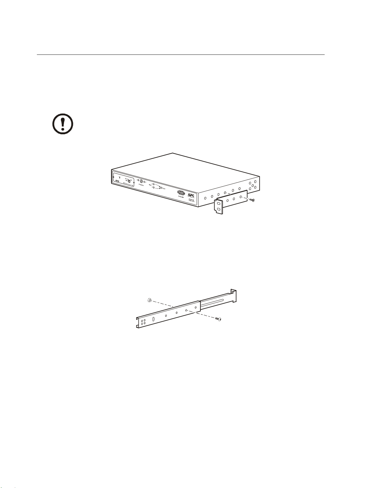
Attach mounting brackets
Attach the left and right mounting brackets to the unit, using two flat-head, Phillips screws (provided)
for each bracket.
Place the brackets flush with the front of the rack to leave room for routing cables.
Note
mph0096a
Disassemble the adjustable brackets
The adjustable brackets are necessary only if you are using a four-post enclosure or rack. If you are
using a two-post rack, the Automatic Transfer Switch is supported by the mounting brackets alone.
1. Disassemble each adjustable bracket by removing the slide screw and nut.
mph0014a
2. Set the screws, nuts, and adjustable bracket segments aside.
4 Automatic Transfer Switch - Installation and Quick Start
Page 9

Attach rear segments to the rack
1. Insert caged nuts (provided with your enclosure) on the enclosure’s rear vertical mounting rails
at your chosen location.
2. Align the rear segments of the adjustable bracket with the caged nuts you inserted in step 1.
3. Insert and tighten mounting screws (provided).
Installation
Attach front segments to the switch
1. Align the front segments of the adjustable bracket with the four corresponding holes on the
sides of the switch.
2. Attach both front segments to the switch using two Phillips pan-head screws (provided) for each
bracket segment.
mph0013a
mph009 5a
Automatic Transfer Switch - Installation and Quick Start 5
Page 10
Installation
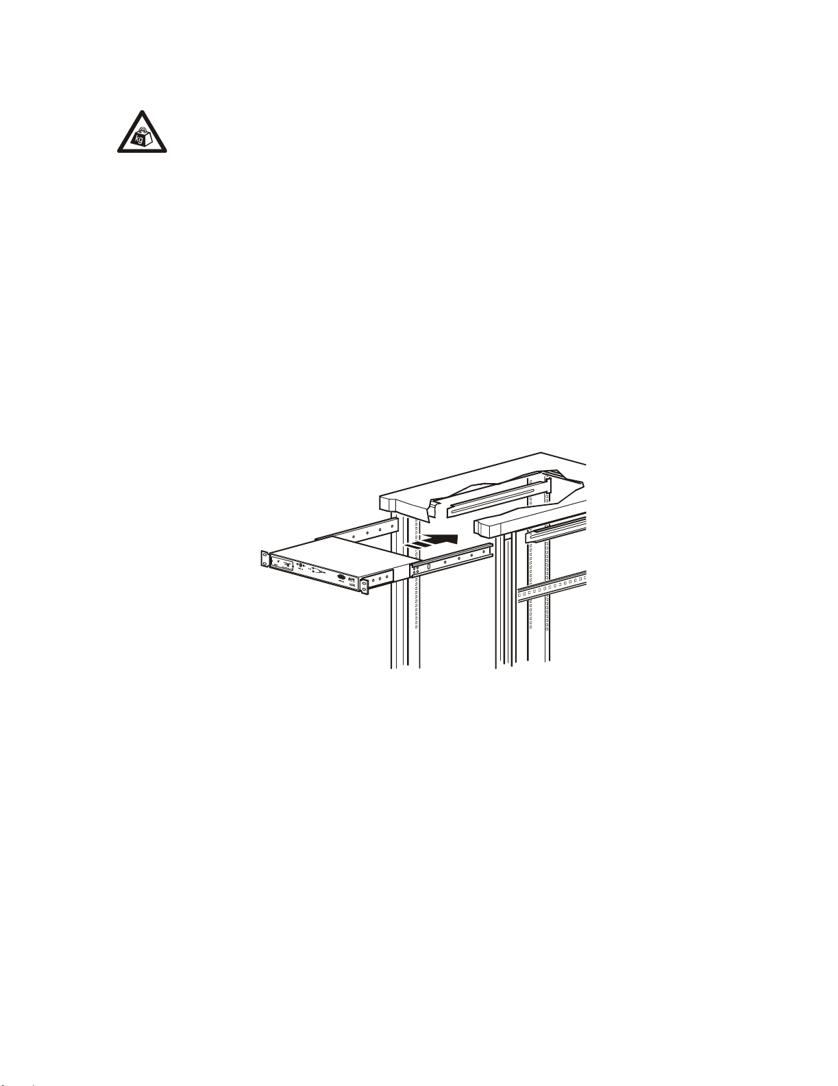
Mount the Automatic Transfer Switch in the enclosure
Two people should perform this procedure.
Heavy
1. Position the Automatic Transfer Switch in front of the mounted rear adjustable bracket
segments.
2. Align the front and rear adjustable bracket segments, and slide the front segments onto the rear
segments.
3. Align the mounting brackets on the switch with the enclosure’s front vertical mounting rails and
insert caged nuts (provided) in the appropriate holes on the front vertical mounting rails.
4. Insert and tighten the mounting screws (provided).
5. Insert slide screws and nuts (removed previously) into each adjustable bracket, and tighten them
to secure the positions of the adjustable brackets.
6 Automatic Transfer Switch - Installation and Quick Start
mph0012a
Page 11

Quick Configuration
Disregard the procedures in this section if you have APC InfraStruXure
Manager as part of your system. See the InfraStruXure Manager’s
Warning
Overview
You must configure the following TCP/IP settings before the Automatic Transfer Switch can operate
on a network:
documentation for more information.
• IP address of the Automatic Transfer Switch
• Subnet mask
• Default gateway
If a default gateway is unavailable, use the IP address of a computer that is located
on the same subnet as the Automatic Transfer Switch and that is usually running.
Note
The Automatic Transfer Switch uses the default gateway to test the network when
traffic is very light. See “Watchdog Features” in the “Introduction” of the
Automatic Transfer Switch User’s Guide for more information about the watchdog
role of the default gateway.
TCP/IP configuration methods
Use one of the following methods to define the TCP/IP settings needed by the Automatic Transfer
Switch:
• Device IP Configuration Wizard (See “Device IP Configuration Wizard” on page 8.)
• BOOTP or DHCP server (See “BOOTP & DHCP configuration” on page 8.)
• Local computer (See “Local access to the control console” on page 10.)
• Networked computer (See “Remote access to the control console” on page 15.)
Automatic Transfer Switch - Installation and Quick Start 7
Page 12

Quick Configuration
Device IP Configuration Wizard
You can use the Device IP Configuration Wizard on a Windows NT® 4.0, Windows 2000®, Windows
2003, or Windows XP computer to discover unconfigured Automatic Transfer Switches and
configure their basic TCP/IP settings.
To configure one or more Automatic Transfer Switches by exporting configuration settings
from a configured Automatic Transfer Switch, see “How to Export Configuration
See also
Settings” in the User’s Guide on the Utility CD.
1. Insert the APC Automatic Transfer Switch Utility CD into a computer on your network.
2. Select the Device IP Configuration Wizard from the main menu.
3. Wait for the Wizard to discover the first unconfigured Automatic Transfer Switch, then follow
the on-screen instructions.
If you leave the Start a Web browser when finished option enabled, you can use
apc for both the User Name and Password to access the Automatic Transfer
Note
Switch through your browser.
BOOTP & DHCP configuration
The Boot Mode Setting, a TCP/IP option in the Automatic Transfer Switch’s Network menu,
identifies how the TCP/IP settings will be defined. The possible settings are Manual, DHCP only,
BOOTP only, and DHCP & BOOTP (the default setting).
The DHCP & BOOTP setting assumes that a properly configured DHCP or BOOTP
server is available to provide TCP/IP settings to Automatic Transfer Switches.
Note
If these servers are unavailable, see:
• “Device IP Configuration Wizard” on this page.
• “Local access to the control console” on page 10.
• “Remote access to the control console” on page 15.
With Boot Mode set to DHCP & BOOTP, the Automatic Transfer Switch attempts to discover a
properly configured server. It first searches for a BOOTP server, then a DHCP server, and repeats this
pattern until it discovers a BOOTP or DHCP server.
For more information, see “BOOTP” on page 9 or “DHCP” on page 9.
Note
8 Automatic Transfer Switch - Installation and Quick Start
Page 13

Quick Configuration
BOOTP. You can use an RFC951-compliant BOOTP server to configure the TCP/IP settings for the
Automatic Transfer Switch.
The DHCP & BOOTP setting assumes that a properly configured DHCP or BOOTP
server is available to provide TCP/IP settings to Automatic Transfer Switches.
Note
1. Enter the Automatic Transfer Switch’s MAC and IP addresses, the subnet mask and default
gateway settings, and an optional Bootup file name in the BOOTPTAB file of the BOOTP
server.
For the MAC address, look on the bottom of the Automatic Transfer Switch or on
the Quality Assurance slip included in the package.
See also
2. When the Automatic Transfer Switch reboots, the BOOTP server provides it with the TCP/IP
settings.
– If you specified a bootup file name, the Automatic Transfer Switch attempts to transfer that
file from the BOOTP server using TFTP or FTP. The Automatic Transfer Switch assumes all
settings specified in the bootup file.
To create the bootup file, see your BOOTP server documentation
See also
– If you did not specify a bootup file name, the Automatic Transfer Switch can be configured
remotely by using Telnet or by using the Web interface: User Name and Password are both
apc, by default.
DHCP. You can use a RFC2131/RFC2132-compliant DHCP server to configure the TCP/IP settings
for the Automatic Transfer Switch.
This section briefly summarizes the Automatic Transfer Switch communication with a
DHCP server. For more detail about how a DHCP server is used to configure the
See also
network settings for a Automatic Transfer Switch, see “DHCP Configuration” in the
Automatic Transfer Switch User’s Guide.
1. An Automatic Transfer Switch sends out a DHCP request that uses the following to identify
itself:
– A Vendor Class Identifier (APC by default)
– A Client Identifier (by default, the Automatic Transfer Switch’s MAC address value)
– A User Class Identifier (by default, the identification of the Automatic Transfer Switch’s
application firmware)
Automatic Transfer Switch - Installation and Quick Start 9
Page 14

Quick Configuration
2. A properly configured DHCP server responds with a DHCP offer that includes all of the
settings that the Automatic Transfer Switch needs for network communication. The DHCP offer
also includes the Vendor Specific Information option (DHCP option 43). By default, the
Automatic Transfer Switch will ignore DHCP offers that do not encapsulate the APC cookie in
the Vendor Specific Information option using the following hexidecimal format:
Option 43 = 01 04 31 41 50 43
where
– the first byte (
– the second byte (
– the remaining bytes (
01) is the code
04) is the length
31 41 50 43) are the APC cookies
See your DHCP server documentation to add code to the Vendor Specific
Information option.
See also
To disable the APC cookie requirement, see “Remote access to the control
console” on page 15. To change the control console’s DHCP Cookie Is setting,
use the Advanced option in the TCP/IP menu. See “Remote access to the control
console” on page 15.
Local access to the control console
1. Select a serial port at the local computer and disable any service that uses that port.
2. Connect APC serial cable 990-1000A to the Automatic Transfer Switch serial port and to the
serial port on the local computer. Run a terminal program (such as Windows HyperTerminal
and configure the selected port for 19200 bps, 8 data bits, no parity, 1 stop bit, and no flow
control, and save the changes.
®
3. Press
ENTER and log on as the Automatic Transfer Switch administrator. Select option 11, Web
config, from the main menu and then disconnect the terminal program.
4. Reconfigure the selected port for 2400 bps, 8 data bits, no parity, 1 stop bit, and no flow control,
and reconnect HyperTerminal.
5. Press
10 Automatic Transfer Switch - Installation and Quick Start
ENTER to display the User Name prompt.
Page 15

How to Access the Automatic Transfer Switch Interfaces
Overview
After the Automatic Transfer Switch is running on your network, you can use the interfaces
summarized here to access the unit.
For more information on the interfaces, see the User’s Guide.
See also
Web interface
As your browser, you can use Microsoft® Internet Explorer 5.0 (and higher) or Netscape® 6.x to
access the Network Management Card through its Web interface. Other commonly available
browsers also may work but have not been fully tested by APC.
To use the Web browser to configure the Automatic Transfer Switch options or to view the event log,
you can use either of the following:
• The HTTP protocol (enabled by default), which provides authentication by user name and
password but no encryption.
• The more secure HTTPS protocol, which provides extra security through Secure Sockets Layer
(SSL) and encrypts user names, passwords, and data being transmitted. It also provides
authentication of Network Management Cards by means of digital certificates.
To access the Web interface and configure the security of your device on the network:
1. Address the Network Management Card by its IP address or DNS name (if configured).
2. Enter the user name and password (by default, apc and apc for an Administrator, or device and
apc for a Device Manager).
3. Select and configure the type of security you want. (This option is available only for
Administrators.)
See the chapter entitled “Security” in the User’s Guide for information on choosing
and setting up your network security. Use the Web/SSL option of the Network menu
See also
to enable or disable the HTTP or HTTPS protocols.
Automatic Transfer Switch - Installation and Quick Start 11
Page 16

How to Access the Automatic Transfer Switch Interfaces
Telnet/SSH
You can access the control console through Telnet or Secure SHell (SSH), depending on which is
enabled. (An Administrator can enable these access methods through the Tel ne t/ SS H option of the
Network menu.) By default, Telnet is enabled. Enabling SSH automatically disables Telnet.
Telnet for basic access. Telnet provides the basic security of authentication by user name and
password, but not the high-security benefits of encryption. To use Telnet to access an Automatic
Transfer Switch’s control console from any computer on the same subnet:
1. At a command prompt, use the following command line, and press
telnet address
ENTER:
As address, use the Network Management Card’s IP address or DNS name (if configured).
2. Enter the user name and password (by default, apc and apc for an Administrator, or device and
apc for a Device Manager).
SSH for high-security access. If you use the high security of SSL for the Web interface, use
Secure SHell (SSH) for access to the control console. SSH encrypts user names, passwords, and
transmitted data.
The interface, user accounts, and user access rights are the same whether you access the control
console through SSH or Telnet, but to use SSH, you must first configure SSH and have an SSH client
program installed on your computer.
See the User’s Guide for more information on configuring and using SSH.
See also
SNMP
After you add the PowerNet MIB to a standard SNMP MIB browser, you can use that browser for
SNMP access to the Automatic Transfer Switch. The default read community name is public; the
default read/write community name is private.
If you enable SSL and SSH for their high-security authentication and encryption, disable
SNMP. Allowing SNMP access to the Automatic Transfer Switch compromises the high
Note
security you implement by choosing SSL and SSH. To disable SNMP, you must be an
Administrator; use the SNMP option of the Network menu.
12 Automatic Transfer Switch - Installation and Quick Start
Page 17

How to Access the Automatic Transfer Switch Interfaces
FTP/SCP
You can use FTP (enabled by default) or Secure CoPy (SCP) to transfer new firmware to the
Automatic Transfer Switch, or to access a copy of the Automatic Transfer Switch’s event logs. SCP
provides the higher security of encrypted data transmission and is enabled automatically when you
enable SSH.
If you enable SSL and SSH for their high-security authentication and encryption, disable
FTP. Allowing file transfer to the Automatic Transfer Switch through FTP compromises
Note
the high security you implement by choosing SSL and SSH. To disable FTP, you must be
an Administrator; use the FTP Server option of the Network menu.
To access the Automatic Transfer Switch through FTP or SCP, the default user name and password
are apc and apc for an Administrator, or device and apc for a Device Manager. In the command line,
use the IP address of the unit.
See the User’s Guide to use FTP or SCP to transfer firmware files to the Network
Management Card or to retrieve log files from the Network Management Card.
See also
Automatic Transfer Switch - Installation and Quick Start 13
Page 18

Configuring the ATS
Configuring sensitivity
The sensitivity setting controls how tolerant the ATS is of fluctuations in power before it switches to
the secondary power source. Configure the sensitivity range for your ATS using the Switch
Configuration menu. When sensitivity is set to low, the ATS will wait 5 ms before switching to the
alternate power source when there is a disturbance in the power supply. When sensitivity is set to
high, the ATS will wait 3 ms before transferring power. The default setting is high.
Configuring voltage transfer range
The voltage transfer range determines the acceptable RMS voltages for the ATS. When voltage
moves outside the specified range, the ATS switches to the secondary power source. Configure the
voltage transfer range using the Switch Configuration menu. The ATS can be set to narrow,
medium, or wide voltage ranges depending on the power conditions of your system.
The default setting of the voltage range is Medium.
Note
APC Part Number
AP7701 120 V 20 (110–130 V) 23 (108.5–131.5 V) 27 (106.5–133.5 V)
AP7722 230 V 30 (215–245 V) 35 (212.5–247.5 V) 40 (210–250 V)
AP7750 120 V 20 (110–130 V) 23 (108.5–131.5 V) 27 (106.5–133.5 V)
Nominal Voltage
(L–N)
Narrow Medium Wide
14 Automatic Transfer Switch - Installation and Quick Start
Page 19

Configuring the ATS
Remote access to the control console
From any computer on the same subnet as the Automatic Transfer Switch, you can use ARP and Ping
to assign an IP address to a Automatic Transfer Switch, and then use Telnet to access that Automatic
Transfer Switch’s control console and configure the needed TCP/IP settings.
After the Automatic Transfer Switch has its IP address configured, you can use Telnet,
without first using ARP and Ping, to access that Automatic Transfer Switch.
Note
Use ARP to define an IP address for the Automatic Transfer Switch, and use the Automatic Transfer
Switch’s MAC address in the ARP command. For example, to define an IP address of
156.205.14.141 for a Automatic Transfer Switch that has a MAC address of 00 c0 b7 63 9f 67, use
one of the following commands:
– Windows command format:
arp -s 156.205.14.141 00-c0-b7-63-9f-67
– LINUX command format:
arp -s 156.205.14.141 00:c0:b7:63:9f:67
Automatic Transfer Switch - Installation and Quick Start 15
Page 20

Recovering From A Lost Password
Use the following instructions to reset the Network Management Card password.
Note
1. Select a serial port at the local computer and disable any service that uses that port.
2. Connect APC serial cable 990-1000A to the Automatic Transfer Switch serial port and to the
serial port on the local computer. Run a terminal program (such as Windows HyperTerminal)
and configure the selected port for 19200 bps, 8 data bits, no parity, 1 stop bit, and no flow
control, and save the changes.
3. Press
ENTER and log on as the Automatic Transfer Switch administrator. Select option 11, Web
config from the main menu and then disconnect the terminal program.
4. Reconfigure the selected port for 2400 bps, 8 data bits, no parity, 1 stop bit, and no flow control,
and reconnect HyperTerminal.
5. Press
6. Press the
ENTER to display the User Name prompt.
RESET button on the Network Management Card, which causes the Network
Management Card to restart, a process that typically takes approximately 15 seconds.
7. Press
ENTER as many times as necessary to re-display the User Name prompt, then use apc for
the user name and password. (If you take longer than 30 seconds to log on after the User Name
prompt is redisplayed, you must start the login procedure again at step 5.)
8. From the Control Console menu, select System, then User Manager.
9. Select Administrator, and change the User Name and Password settings, both of which was
originally defined as apc.
10. Press
CTRL-C and log off. You must perform the entire procedure (log on, change the user name
and password, and log off) within two minutes so that you are not logged off for inactivity. If
you are logged off automatically, the new settings will not take effect and you must repeat the
entire procedure from the beginning.
11. Press and hold down the Preference button on the Automatic Transfer Switch, which causes the
Automatic Transfer Switch to reset, typically in 10 to 15 seconds.
12. Reconfigure the selected port for 19200 bps, 8 data bits, no parity, 1 stop bit, and no flow
control, and reconnect HyperTerminal.
16 Automatic Transfer Switch - Installation and Quick Start
Page 21

Warranty
Limited warranty
APC warrants the Automatic Transfer Switch to be free from defects in materials and workmanship
for a period of two years from the date of purchase. Its obligation under this warranty is limited to
repairing or replacing, at its own sole option, any such defective products. This warranty does not
apply to equipment that has been damaged by accident, negligence, or misapplication or has been
altered or modified in any way. This warranty applies only to the original purchaser.
Warranty limitations
Except as provided herein, APC makes no warranties, express or implied, including warranties
of merchantability and fitness for a particular purpose. Some jurisdictions do not permit
limitation or exclusion of implied warranties; therefore, the aforesaid limitation(s) or exclusion(s)
may not apply to the purchaser.
Except as provided above, in no event will
APC be liable for direct, indirect, special, incidental,
or consequential damages arising out of the use of this product, even if advised of the possibility
of such damage.
Specifically,
APC is not liable for any costs, such as lost profits or revenue, loss of equipment, loss of
use of equipment, loss of software, loss of data, costs of substitutes, claims by third parties, or
otherwise. This warranty gives you specific legal rights and you may also have other rights, which
vary according to jurisdiction.
Obtaining service
To obtain support for problems with your Automatic Transfer Switch:
0
1. Note the serial number on the bottom of the Automatic Transfer Switch.
2. Contact Customer Support at a phone number on the back cover of this document. A technician
will try to help you solve the problem by phone.
3. If you must return the product, the technician will give you a Return Material Authorization
(RMA) number. If the warranty expired, you will be charged for repair or replacement.
Automatic Transfer Switch - Installation and Quick Start 17
Page 22

Warranty
4. Pack the unit carefully. The warranty does not cover damage sustained in transit. Enclose a
letter with your name, address, RMA number and daytime phone number; a copy of the sales
receipt; and a check as payment, if applicable.
5. Mark the RMA number clearly on the outside of the shipping carton.
6. Ship by insured, prepaid carrier to the address provided by the Customer Support technician.
18 Automatic Transfer Switch - Installation and Quick Start
Page 23

Life-Support Policy
General policy
American Power Conversion (APC) does not recommend the use of any of its products in the
following situations:
• In life-support applications where failure or malfunction of the
APC product can be reasonably
expected to cause failure of the life-support device or to affect significantly its safety or
effectiveness.
• In direct patient care.
APC will not knowingly sell its products for use in such applications unless it receives in writing
assurances satisfactory to
APC that (a) the risks of injury or damage have been minimized, (b) the
customer assumes all such risks, and (c) the liability of American Power Conversion is adequately
protected under the circumstances.
a
Examples of life-support devices
The term life-support device includes but is not limited to neonatal oxygen analyzers, nerve
stimulators (whether used for anesthesia, pain relief, or other purposes), autotransfusion devices,
blood pumps, defibrillators, arrhythmia detectors and alarms, pacemakers, hemodialysis systems,
peritoneal dialysis systems, neonatal ventilator incubators, ventilators (for adults and infants),
anesthesia ventilators, infusion pumps, and any other devices designated as “critical” by the
FDA
.
U.S.
Hospital-grade wiring devices and leakage current protection may be ordered as options on many
APC UPS systems. APC does not claim that units with these modifications are certified or listed as
hospital-grade by
APC or any other organization. Therefore these units do not meet the requirements
for use in direct patient care.
Automatic Transfer Switch - Installation and Quick Start 19
Page 24

Radio Frequency Interference
Changes or modifications to this unit not expressly approved
by the party responsible for compliance could void the user’s
Warning
USA—FCC
This equipment has been tested and found to comply with the limits for a Class A digital device,
pursuant to part 15 of the FCC Rules. These limits are designed to provide reasonable protection
against harmful interference when the equipment is operated in a commercial environment. This
equipment generates, uses, and can radiate radio frequency energy and, if not installed and used in
accordance with this user manual, may cause harmful interference to radio communications.
Operation of this equipment in a residential area is likely to cause harmful interference. The user will
bear sole responsibility for correcting such interference.
authority to operate this equipment.
Canada— ICES
This Class A digital apparatus complies with Canadian ICES-003.
Cet appareil numérique de la classe A est conforme à la norme NMB-003 du Canada.
Japan—VCCI
This is a Class A product based on the standard of the Voluntary Control Council for Interference by
Information Technology Equipment (VCCI). If this equipment is used in a domestic environment,
radio disturbance may occur, in which case, the user may be required to take corrective actions.
この装置は、情報処理装置等電波障害自主規制協議会(VCCI)の基準に基づくクラス A
情報技術装置です。この装置を家庭環境で使用すると、電波妨害を引き起こすことがあり
ます。この場合には、使用者が適切な対策を講ずるように要求されることがあります。
20 Automatic Transfer Switch - Installation and Quick Start
Page 25

APC Worldwide Customer Support
Customer support for this or any other APC product is available at no charge in any of the following ways:
• Visit the APC Web site to access documents in the APC Knowledge Base and to submit customer
support requests.
– www.apc.com (Corporate Headquarters)
Connect to localized APC Web sites for specific countries, each of which provides customer support
information.
– www.apc.com/support/
Global support searching APC Knowledge Base and using e-support.
• Contact an APC Customer Support center by telephone or e-mail.
– Regional centers:
Direct InfraStruXure Customer Support Line
APC headquarters U.S., Canada (1)(800) 800-4272 (toll free)
Latin America
Europe, Middle East, Africa
Japan
Australia, New Zealand, South Pacific area
(1)(877) 537-0607 (toll free)
(1)(401) 789-5735 (USA)
(353)(91)702000 (Ireland)
(0) 35434-2021
(61) (2) 9955 9366 (Australia)
– Local, country-specific centers: go to www.apc.com/support/contact for contact information.
Contact the
APC representative or other distributor from whom you purchased your APC product for
information on how to obtain local customer support.
Entire contents copyright 2005 American Power Conversion Corporation. All rights reserved.
Reproduction in whole or in part without permission is prohibited. APC, the APC logo, PowerNet, and
InfraStruXure are trademarks of American Power Conversion Corporation. All other trademarks, product
names, and corporate names are the property of their respective owners and are used for informational
purposes only.
10/2005990-1233E-001
*990-1233E-001*
 Loading...