

Page 1
Operation
Symmetra™PX
48,96,and160kW400V
100kW208V
Page 2

LegalDisclaimer
TheinformationpresentedinthismanualisnotwarrantedbytheSchneiderElectricIT
Corporationtobeauthoritative,errorfree,orcomplete.Thispublicationisnotmeanttobea
substituteforadetailedoperationalandsitespecicdevelopmentplan.Therefore,Schneider
ElectricITCorporationassumesnoliabilityfordamages,violationsofcodes,improper
installation,systemfailures,oranyotherproblemsthatcouldarisebasedontheuseofthis
Publication.
TheinformationcontainedinthisPublicationisprovidedasisandhasbeenpreparedsolely
forthepurposeofevaluatingdatacenterdesignandconstruction.ThisPublicationhasbeen
compiledingoodfaithbySchneiderElectricITCorporation.However,nopresentationor
warranty,eitherexpressorimplied,ismadeastothecompletenessoraccuracyoftheinformation
thisPublicationcontains.
INNOEVENTSHALLSCHNEIDERELECTRICITCORPORA TIONBELIABLE
FORANYDIRECT,INDIRECT,CONSEQUENTIAL,PUNITIVE,SPECIAL,OR
INCIDENTALDAMAGES(INCLUDING,WITHOUTLIMIT A TION,DAMAGESFOR
LOSSOFBUSINESS,CONTRACT,REVENUE,DAT A,INFORMA TION,ORBUSINESS
INTERRUPTION)RESULTINGFROM,ARISINGOUTOF ,ORINCONNECTIONWITH
THEUSEOF,ORINABILITYTOUSETHISPUBLICA TIONORTHECONTENT,EVEN
IFSCHNEIDERELECTRICITCORPORATIONHASBEENEXPRESSL YADVISEDOF
THEPOSSIBILITYOFSUCHDAMAGES.SCHNEIDERELECTRICITCORPORATION
RESERVESTHERIGHTTOMAKECHANGESORUPDA TESWITHRESPECTTOOR
INTHECONTENTOFTHEPUBLICA TIONORTHEFORMATTHEREOFATANYTIME
WITHOUTNOTICE.
Copyright,intellectual,andallotherproprietaryrightsofthecontent(includingbutnotlimitedto
software,audio,video,text,andphotographs)restswithSchneiderElectricITCorporationorits
licensors.Allrightsinthecontentnotexpresslygrantedhereinarereserved.Norightsofany
kindarelicensedorassignedorshallotherwisepasstopersonsaccessingthisinformation.
ThisPublicationshallnotbeforresaleinwholeorinpart.
Page 3

TableofContents
AboutthisManual..........................................................................................................1
CompanionManuals...................................................................................................1
FindUpdatestothisManual.....................................................................................1
Overview..............................................................................................................................2
UserInterface................................................................................................................2
DisplayInterface........................................................................................................3
Operation............................................................................................................................7
Modes..............................................................................................................................7
NormalOperation......................................................................................................7
BatteryOperation......................................................................................................7
StaticBypassOperation............................................................................................7
MaintenanceBypassOperation(Optional)................................................................7
OperationProcedures................................................................................................7
Breakers/SwitchesintheSystem..............................................................................7
PerformaTotalPowerOff..........................................................................................8
StarttheSystemafterT otalPowerOff.......................................................................10
TurntheUPSLoadOff...............................................................................................12
TurntheUPSLoadOn...............................................................................................13
TransfertheUPSintoMaintenanceBypassOperation..............................................14
ReturntoNormalOperationfromMaintenanceBypassOperation............................16
ViewtheStatusScreens............................................................................................19
ViewtheLogScreen..................................................................................................19
Conguration....................................................................................................................20
SystemSettings...........................................................................................................20
SetUptheNetwork....................................................................................................20
ChangetheDisplayInterfaceSettings.......................................................................21
ChangetheDateandTime.........................................................................................22
CongureInputContacts..........................................................................................22
CongureOutputRelays...........................................................................................23
Maintenance......................................................................................................................24
LifeCycleMonitoring(LCM).....................................................................................24
PartsReplacement......................................................................................................24
DetermineifyouNeedaReplacementPart...............................................................24
ReturnPartstoSchneiderElectric............................................................................24
ReplacementParts....................................................................................................26
ReplaceaPowerManagementCard..........................................................................26
ReplaceaPowerModule...........................................................................................27
ReplaceaBattery.......................................................................................................28
ReplaceaPowerDistributionModule........................................................................31
990–3015E-001
Symmetra™PX48,96,and160kW400V100kW208VOperation
i
Page 4

Troubleshooting..............................................................................................................32
StatusandAlarmMessages.....................................................................................32
DisplayMessages......................................................................................................32
ModularDistributionFaultList................................................................................36
PDUFaultList...............................................................................................................37
ii
Symmetra™PX48,96,and160kW400V100kW208VOperation
990–3015E-001
Page 5

AboutthisManual
Thismanualisfor:
•SymmetraPX48kW400VUPS
•SymmetraPX96and160kW400VUPSandPowerDistributionUnit(PDU-XR)
•SymmetraPX100kW208VUPSandPowerDistributionUnit(PDU)
•XRBatteryEnclosure
CompanionManuals
Foradditionalinformation,seethefollowingSymmetraPXmanuals:
•ReceivingandUnpacking(990-3013)
•Safety(990-2984)
•96and160kW400VInstallation(990-3017)
•48kW400VInstallation(990-3151)
•100kW208VInstallation(990-3659)
•48kW400VXRBatteryEnclosure(990-3190)
•BatteryReplacementSheet(990-2958)
FindUpdatestothisManual
Youcancheckforupdatestothismanualonwww.apc.com.Lookforthelatestletterrevision(A,
Betc.)ofthemanual.
990–3015E-001
Symmetra™PX48,96,and160kW400V100kW208VOperation
1
Page 6
Overview
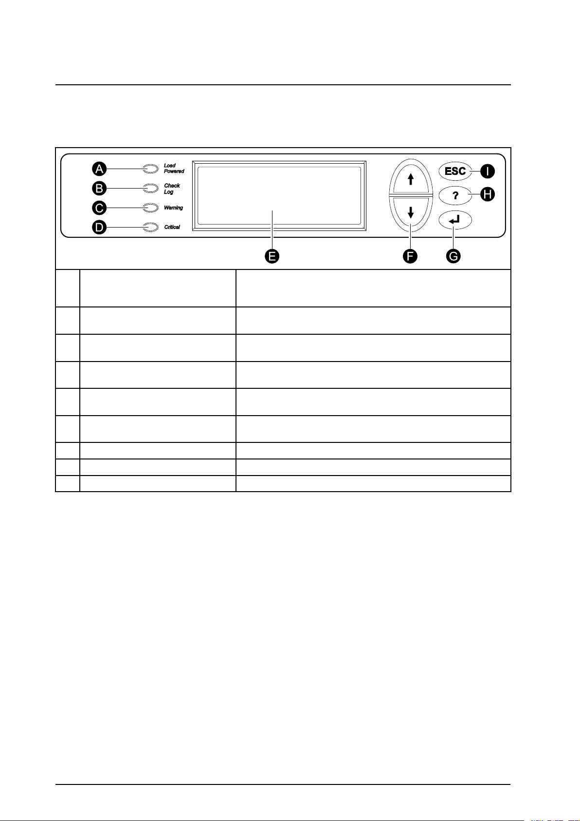
UserInterface
ALOADPOWEREDLED
B
CHECKLOGLED
CWARNINGLED
D
CRITICALLED
E
LCDSCREEN
F
UPANDDOWNNA VIGA TION
KEYS
ENTERKEY
G
HHELPKEY
I
ESCKEY
WhenthisLEDisgreen,powertotheloadison.WhentheLEDis
yellow,theloadissuppliedthroughthebatteries.WhentheLEDis
ashingyellow,theunitisinbypass.
WhenthisLEDisgreen,aneweventhasbeenaddedtotheevent
log.
WhenthisLEDisyellow ,thereareoneormorewarningalarms
inthesystem.
WhenthisLEDisred,thereareoneormorecriticalalarmsinthe
system.
Displaysalarms,statusdata,instructionalhelp,andconguration
items.
Usedtoscrollthroughandselectmenuitems.
Opensmenuitemsandconrmschangestothesystemparameters.
Openscontext-sensitivehelp.
Returnstothepreviousscreendisplayed.
2
Symmetra™PX48,96,and160kW400V100kW208VOperation
990–3015E-001
Page 7
DisplayInterface
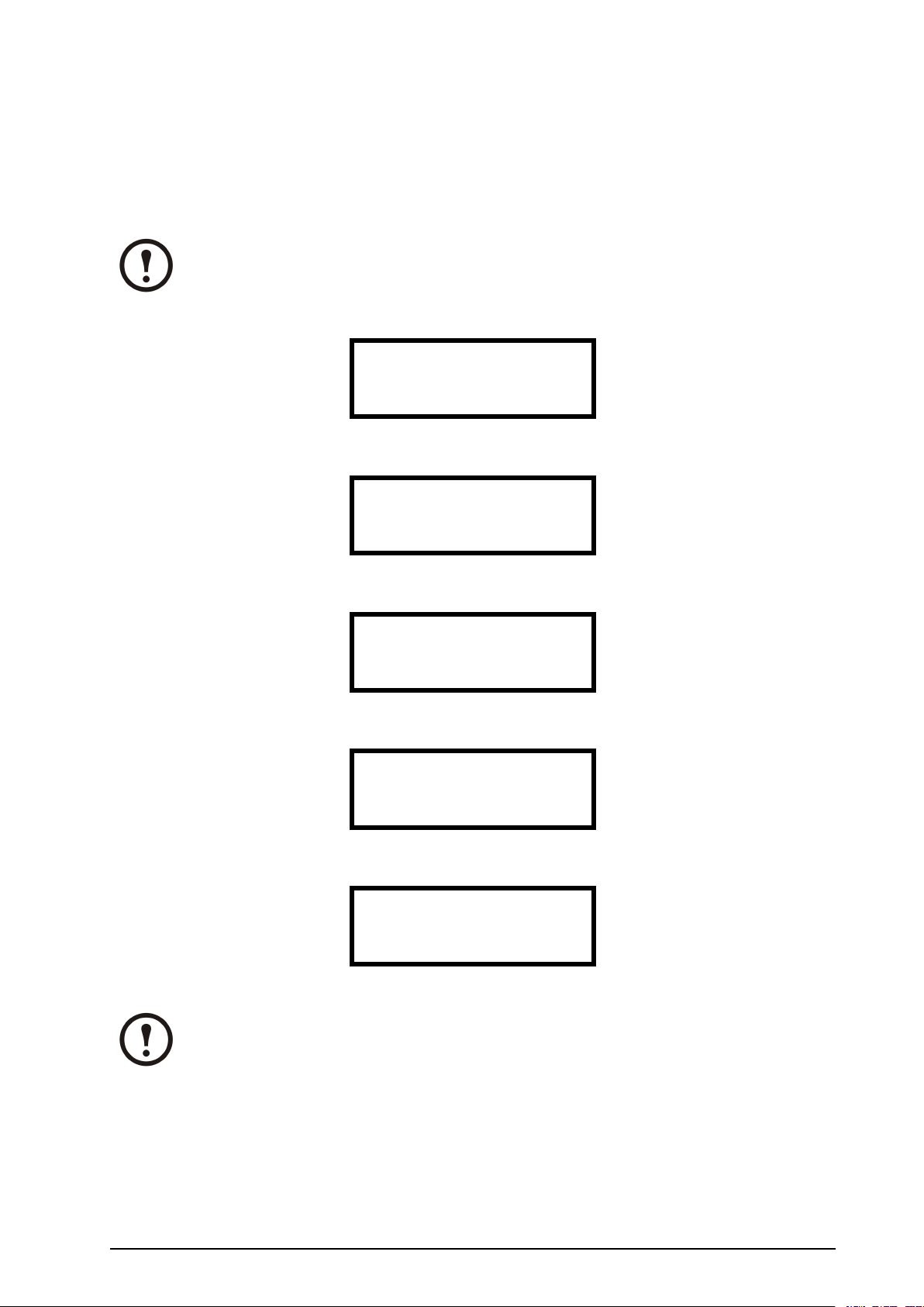
OverviewScreens
TheOverviewScreenisthemainentrancetotheuserfunctionsofthedisplayinterface.TheUP/DOWN
navigationkeystakeyoufromonescreentoanother.Whenthesystemisrunning,thedisplaywillscroll
throughscreensshowinginformationaboutthesystemandanyactivealarms.
Note:Thedatavaluesshownareforexampleonly .
NoActiveAlarms
SystemDate/Time:
28-Mar-201010:37:01
VoltsInVoltsOut
L1:xxxL1:xxx
L2:xxxL2:xxx
L3:xxxL3:xxx
OutAmpskWkVA
L1:xxxxx.xxx.x
L2:xxxxx.xxx.x
L3:xxxxx.xxx.x
SymmetraPX160kW
Runtime:xxhrxxmin
Capacityxxx.x%
UPSLoad:xxx%
SystemBypassState:
UPSOperation
UPSState:
OnLine
Note:PressENTERtogofromanyoverviewscreentothemainmenuscreen.
990–3015E-001
Symmetra™PX48,96,and160kW400V100kW208VOperation
3
Page 8

MainMenuScreen
Fromthemainmenuitispossibletocongureandmonitorthesystemthroughthesubmenuscreens:
UPS,PowerDist,Switchgear,Environment,Alarms,Log,Admin,andHelp.UsetheUPandDOWN
arrowkeystonavigatethroughthemenuscreens.
MainScreen
SystemBypassState:
UPSOperation
UPSState:
OnLine
4
Symmetra™PX48,96,and160kW400V100kW208VOperation
990–3015E-001
Page 9
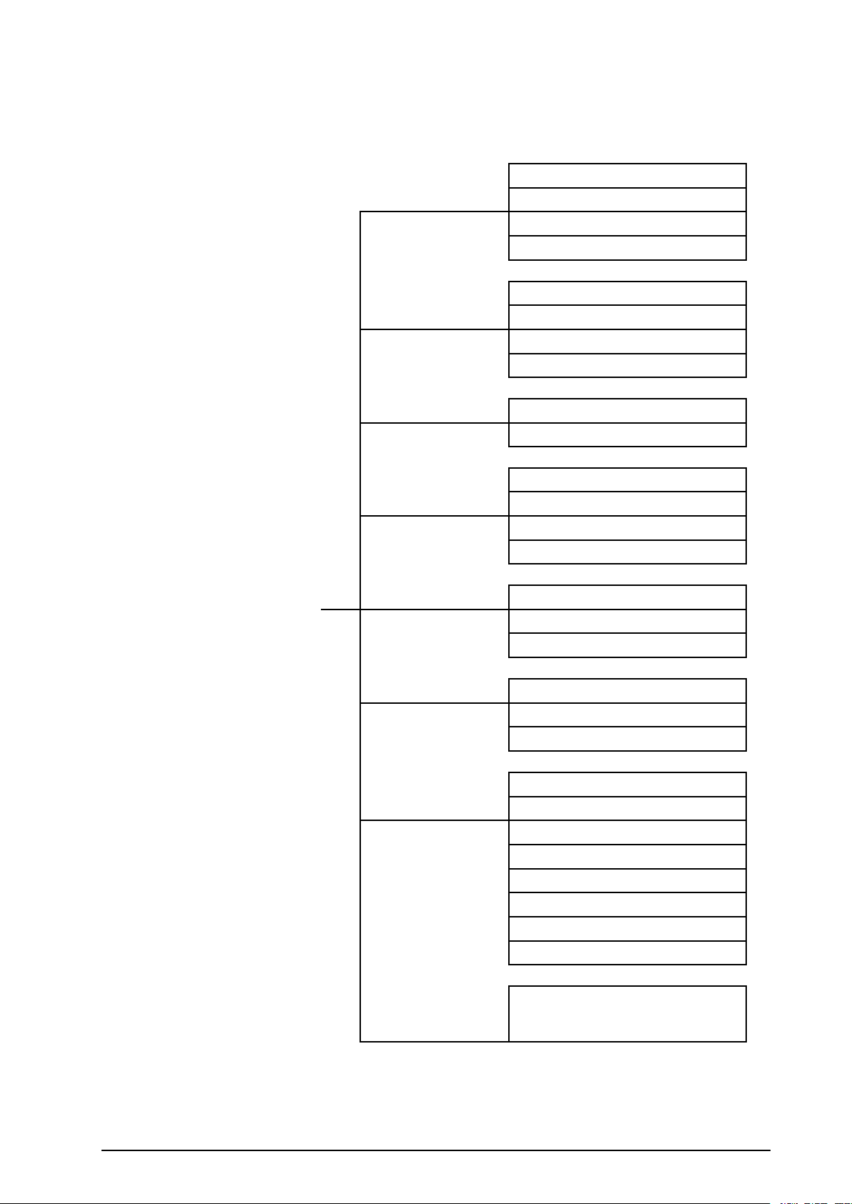
MenuTree
Themenutreeprovidesaquickoverviewofthefunctionsandviewsyoumayaccess.
UPSPowerControl
UPSUPSStatus
UPSTests&Diags
UPSConguration
TotalLoading
PowerDistModularLoading
V olt-Meter
Subfeeds
MainMenuScreen
Switchgear
EnvironmentOutputRelays
AlarmsAllActiveAlarms
Log
AdminLocalInterface
Status
Factory
InputContacts
AlarmRelayMap
EnvMonitoringCard
ActivebySeverity
ActivebyType
ViewNewLogItems
ViewEntireLog
ClearEntireLog
NetworkSetup
Date/Time
DeviceID
ManufacturerData
FactoryDefaults
FirmwareUpgrade
LifecycleMonitor
Onanyscreen
&anyline,press‘?’forcontext
Help
990–3015E-001
Symmetra™PX48,96,and160kW400V100kW208VOperation
sensitivehelp.Tryitnow...
5
Page 10

Caution:Thedisplayprovidesaccesstomorefunctionsthandescribedinthismanual.
ThosefunctionsshouldnotbeaccessedwithouttheassistanceofSchneiderElectric
CustomerSupportinordertoavoidunwantedloadimpacts.ForSchneiderElectric
World-WideCustomerSupport,refertothebackcoverofthismanual.Ifyoubyaccidentgo
beyondthefunctionsdescribed,pressESCtoreturntopreviousscreens.
6
Symmetra™PX48,96,and160kW400V100kW208VOperation
990–3015E-001
Page 11

Operation
Modes
Inaninstallationthatdoesnotincludeamaintenancebypasspanel,theUPShasthreeoperationmodes:
normaloperation,batteryoperationandstaticbypassoperation.IftheinstallationincludesaPDU,a
PDU-XR,oranexternalmaintenancebypasspanel,themodemaintenancebypassoperationalsobecomes
available.
NormalOperation
Duringnormaloperation,theUPSconvertstheutility/mainssupplytoconditionedpowerforthe
connectedload.
BatteryOperation
Duringbatteryoperation,theUPSprovidesconditionedpowertotheconnectedloadfromitsbatteries
foraniteperiod.TheUPStransferstobatteryoperationiftheutility/mainspowersupplyfailsor
isoutsidepre-denedlimits.
StaticBypassOperation
Staticbypassoperationisafeaturethatkeepstheloadsupplieddirectlyfromtheutility/mainssupply
duringdifferentscenariosontheUPSordownstreamfromtheUPS.Instaticbypassoperation,the
utility/mainsissupplyingpowertotheconnectedloaddirectly,bypassingallinternalUPSfunctions.
MaintenanceBypassOperation(Optional)
TheUPScanbeconnectedtoaPDU,aPDU-XR,oranoptionalexternalmaintenancebypasspanel
thatenablestheusertobypasstheUPScompletelyformaintenancepurposesthatmighteveninclude
replacementoftheentireUPS.Theconnectedloadwillthenbefeddirectlyfromtheutility/mainssupply,
andtherewillinthiscasebenolteringofthesupplyorbatterybackupoftheload.
OperationProcedures
Breakers/SwitchesintheSystem
Q1
UPSinput
Q2UPSoutput
Q3
MaintenanceBypass
Q5
StaticBypassinput(onlyindualutility/mainssystems)
Note:IfthesystemdoesnotcontainaPDUorPDU-XR,theQ1,Q2,andQ3switchesand
theQ5breakershouldbelocatedinanoptionalexternalmaintenancebypasspanel.Seethe
documentationincludedwiththemaintenancebypasspanelforadditionalinformation.
990–3015E-001
Symmetra™PX48,96,and160kW400V100kW208VOperation
7
Page 12

PerformaTotalPowerOff
WARNING:Thisprocedurewilldisconnecttheload.
Note:Ifshutdownviathedisplayisdisabled,thenyoucannotperformthisprocedureand
themessage:Commandnotallowed,UPSconguredtonevershutdownappears.If
youwanttoenableshutdownviathedisplay,thisisdonebyaFieldServiceEngineervia
theUPSTuner.
1.SelectUPSandpressENTER.
2.SelectUPSPowerControlandpressENTER.
→UPSAlarm
PowerDistLog
SwitchGearAdmin
EnvironmentHelp
→UPSPowerControl
UPSStatus
UPSTests&Diags
UPSConfiguration
3.SelectTurnUPSOffandpressENTER.
4.SelectNo,Don’tNotifytoshutdownwithout
delayandpressENTER.
Note:Thisactionwillcutallpower
totheloadwithoutshuttingitdown
rst.Ifyouwanttoshutdownthe
serversrst,thenchooseY es,Notify
Servers.Notethatthisfunction
isonlyavailableforserverswith
PowerChute.
5.ConrmYES,T urnUPSOffandpress
ENTER.
→TurnUPSOff
RebootUPS
UPSintoBypass
UPStoSleep
NotifyPowerChute?
Cancel
Yes,NotifyServers
→No,Don'tNotify
TurnUPSoff
WithoutServer
Notification?
>NO,ABORT
→>YES,TurnUPSOff
6.WaitfortheUPStoturnoff.
8
Symmetra™PX48,96,and160kW400V100kW208VOperation
TurningUPSoff,
pleasewait...
990–3015E-001
Page 13
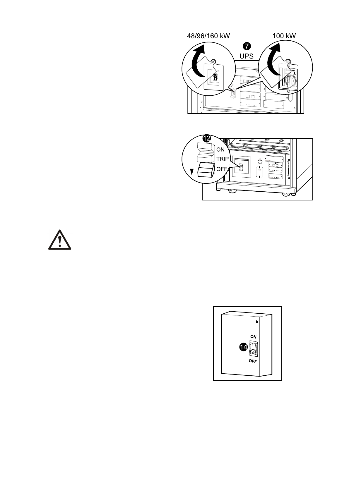
7.SettheUPSSYSTEMENABLEswitchtothe
7
OFFposition.
8.SettheQ2switchtotheOFFposition.
9.SettheQ1switchtotheOFFposition.
10.SettheQ5breakertotheOFFposition(if
applicable).
11.Verifythatthemaintenancebypassswitch
(Q3)isintheOFFposition.
12.SettheDCDISCONNECTswitchonallof
theXRBatteryEnclosuresandthePDU-XR
(ifapplicable)andonthemainframe(onlyfor
PX48)totheOFFposition.
13.Disconnectallbatteryunitsbyremovingthem
orpullingthemouttothereddisconnectline.
Caution:T oensurethatthe
enclosuredoesnottip,donotpull
outthebatteryunitsbeyondthered
disconnectline.Ifyouintendto
completelyremovethebatteryunits,
removethemfromtheenclosureone
atatime.Failuretopullbatteryunits
outtothereddisconnectlinecould
causedeepdischarge/damagetothe
batteries.
XRBatteryEnclosures/PDU-XR
14.SettheupstreammainspowertotheOFFor
LOCKEDOUTposition.IftheUPShasadual
mainssupply,setbothsuppliestotheOFFor
LOCKEDOUTposition.
15.Measurebypass/outputDCandmainsto
ensurethatthesystemiscompletelypowered
off.
990–3015E-001
Symmetra™PX48,96,and160kW400V100kW208VOperation
9
Page 14
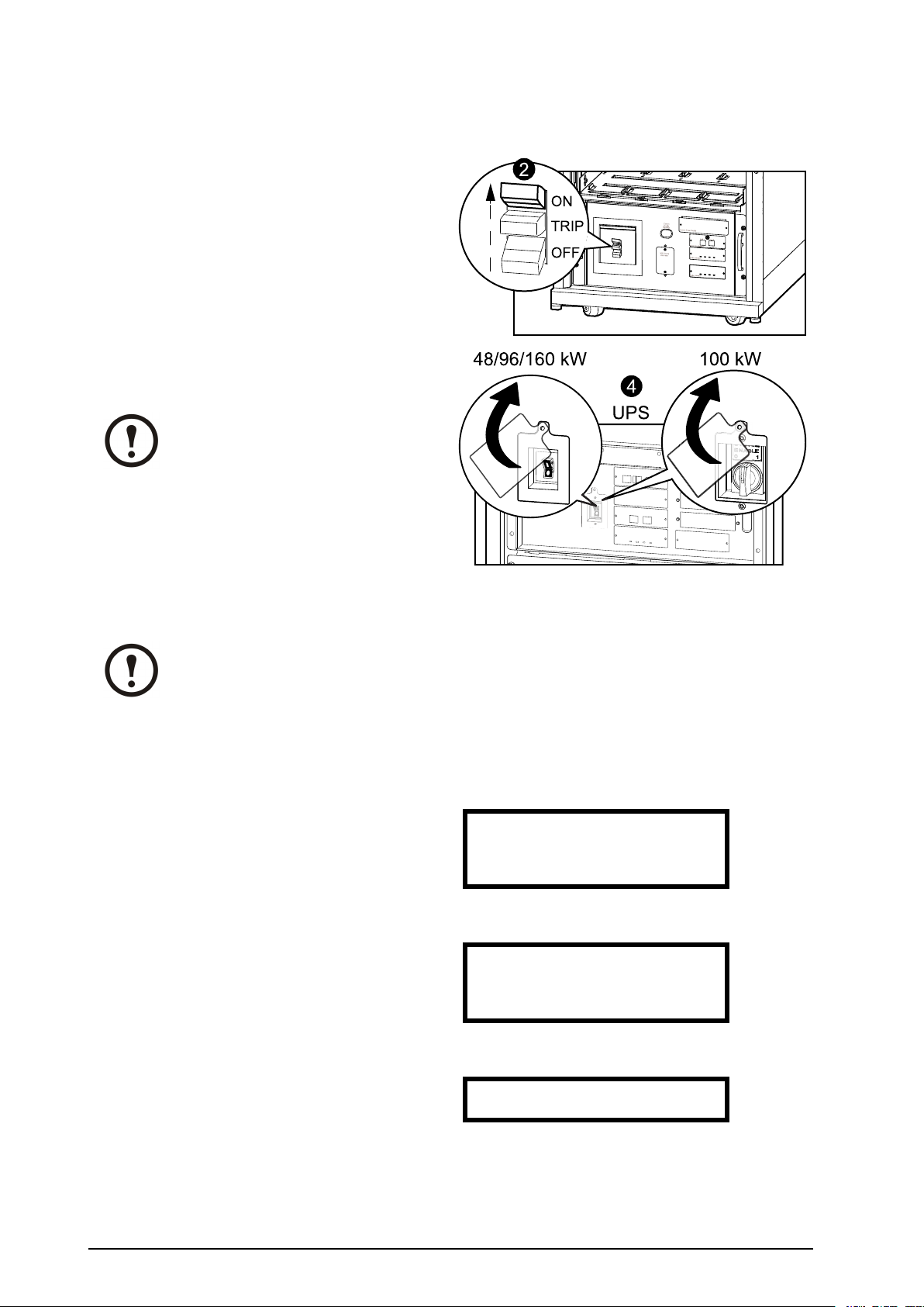
StarttheSystemafterT otalPowerOff
4
1.Settheupstreamutility/mainspowertothe
ONorLOCKEDINposition.IftheUPShasa
dualmainssupply,setbothsuppliestotheON
orLOCKEDINposition.
2.SettheDCDISCONNECTswitchtotheON
positiononallXRBatteryEnclosuresandthe
PDU-XR(ifapplicable)andonthemainframe
(onlyPX48).
3.SettheQ1switchtotheONposition.
4.SettheSYSTEMENABLEswitchontheUPS
totheONposition.
Note:W aitapproximatelytwo
minutesforthesystemtostart.
XRBatteryEnclosures/PDU-XR
5.SettheQ5breakertotheONposition(if
applicable).
Note:TheH2LEDnexttotheQ2
switchwillturnon,indicatingthatit
issafetooperatetheQ2switch.
6.SettheQ2switchonthePDU,PDU-XRor
theexternalmaintenancebypasspaneltothe
ONposition.
7.SelectUPSandpressENTER.
8.SelectUPSPowerControlandpressENTER.
→UPSAlarms
PowerDistLog
SwitchGearAdmin
EnvironmentHelp
→UPSPowerControl
UPSStatus
UPSTests&Diags
UPSConfiguration
9.SelectTurnUPSOnandpressENTER.
10
Symmetra™PX48,96,and160kW400V100kW208VOperation
→TurnUPSOn
UPSOnIntoBypass
990–3015E-001
Page 15

10.ConrmbyselectingY es,TurnUPSOnand
pressENTER.
11.WaitfortheUPStoturnon.
Confirm:
TurnUPSOn?
>NO,ABORT
→>Yes,TurnUPSOn
TurningUPSon,
Pleasewait...
990–3015E-001
Symmetra™PX48,96,and160kW400V100kW208VOperation
11
Page 16

TurntheUPSLoadOff
1.SelectUPSandpressENTER.
2.SelectUPSPowerControlandpressENTER.
3.SelectTurnUPSOffandpressENTER.
4.SelectNo,Don’tNotifyandpressENTER.
Note:Thisactionwillcutallpower
totheloadwithoutshuttingitoff
rst.Ifyouwanttoshutdownthe
serversrst,thenchooseY es,Notify
Servers.Notethatthisfunction
isonlyavailableforserverswith
PowerChute.
→UPSAlarms
PowerDistLog
SwitchGearAdmin
EnvironmentHelp
→UPSPowerControl
UPSStatus
UPSTests&Diags
UPSConfiguration
→TurnUPSOff
RebootUPS
UPSIntoBypass
UPSToSleep
NotifyPowerChute?
Cancel
Yes,NotifyServers
→No,Don'tNotify
5.ConrmYES,T urnUPSOffandpress
ENTER.
6.WaitfortheUPStoturnoff.
TurnUPSOffWithout
ServerNotification?
>NO,ABORT
→YES,TurnUPSOff
TurningUPSoff,
pleasewait...
12
Symmetra™PX48,96,and160kW400V100kW208VOperation
990–3015E-001
Page 17

TurntheUPSLoadOn
1.SelectUPSandpressENTER.
2.SelectUPSPowerControlandpressENTER.
3.SelectTurnUPSOnandpressENTER.
→UPSAlarms
PowerDistLog
SwitchGearAdmin
EnvironmentHelp
→UPSPowerControl
UPSStatus
UPSTests&Diags
UPSConfiguration
Press
Press
4.ConrmbyselectingY es,TurnUPSOnand
pressENTER.
5.WaitfortheUPStoturntheloadon.
→TurnUPSOn
UPSOnIntoBypass
Confirm:
TurnUPSOn?
>NO,ABORT
→>YES,TurnUPSOn
TurningUPSon,
pleasewait...
Press
Press
990–3015E-001
Symmetra™PX48,96,and160kW400V100kW208VOperation
13
Page 18

TransfertheUPSintoMaintenanceBypassOperation
Note:Ifshutdownviathedisplayisdisabled,thenyoucannotperformthisprocedureand
themessage:Commandnotallowed,UPSconguredtonevershutdownappears.If
youwanttoenableshutdownviathedisplay ,thisisdonebyanFieldServiceEngineer
viatheUPSTuner.
1.SelectUPSandpressENTER.
2.SelectUPSPowerControlandpressENTER.
3.SelectUPSintoBypassandpressENTER.
→UPSAlarms
PowerDistLog
SwitchGearAdmin
EnvironmentHelp
→UPSPowerControl
UPSStatus
UPSTests&Diags
UPSConfiguration
TurnUPSOff
RebootUPS
→UPSintoBypass
UPStoSleep
4.SelectYes,IntoBypassandpressENTER.
5.Waitforthetransfertocomplete.
6.Conrmthatthetransfertobypassiscomplete.
Note:TheH3LEDnexttotheQ3
switchwillturnon,indicatingthatit
isoktooperatetheQ3switch.
7.SettheQ3switchtotheONposition.
Note:TheH2LEDbesidetheQ2
switchwillturnon,indicatingthatit
isoktooperatetheQ2switch.
Confirm:
UPSintoBypass?
NO,ABORT
→YES,IntoBypass
PuttingUPSinto
Bypass,please
wait....
UPSisnowin
Bypass.
Pressanykey....
8.SettheQ2switchtotheOFFposition.
14
Symmetra™PX48,96,and160kW400V100kW208VOperation
990–3015E-001
Page 19

9.SelectUPSandpressENTER.
15
10.SelectUPSPowerControlandpressENTER.
11.SelectTurnUPSOffandpressENTER.
12.SelectNo,Don’tNotifyandpressENTER.
→UPSAlarms
PowerDistLog
SwitchGearAdmin
EnvironmentHelp
→UPSPowerControl
UPSStatus
UPSTests&Diags
UPSConfiguration
→TurnUPSOff
RebootUPS
UPSintoBypass
UPStoSleep
NotifyPowerChute?
Cancel
Yes,NotifyServers
→No,Don'tNotify
13.ConrmbyselectingYES,T urnUPSOffand
pressENTER.
14.WaitfortheUPStoturnoff.
15.SettheUPSSYSTEMENABLEswitchtothe
OFFposition.
16.SettheQ1switchtotheOFFposition.
17.SettheQ5breakertotheOFFposition(if
applicable).
TurnUPSOffWithout
ServerNotification?
>NO,ABORT
→>YES,TurnUPSOff
TurningUPSoff,
pleasewait....
18.SettheDCDISCONNECTswitchtotheOFF
positiononallXRBatteryEnclosuresandthe
990–3015E-001
Symmetra™PX48,96,and160kW400V100kW208VOperation
XRBatteryEnclosures/PDU-XR
15
Page 20

PDUXR(ifapplicable)andonthemainframe
4
(onlyPX48).
ReturntoNormalOperationfromMaintenanceBypassOperation
1.SettheDCDISCONNECTswitchtotheON
positiononallXRBatteryEnclosuresandthe
PDU-XR(ifapplicable)andonthemainframe
(onlyPX48).
2.SettheQ1switchtotheONposition.
3.SettheSYSTEMENABLEswitchontheUPS
totheONposition.
Note:W aitapproximatelytwo
minutesforthesystemtostart.
4.SettheQ5breakertotheONposition(if
applicable).
5.UsethedisplayinterfacetoturntheUPSload
on.
6.SelectUPSandpressENTER.
→UPSAlarms
PowerDistLog
SwitchGearAdmin
EnvironmentHelp
7.SelectUPSPowerControlandpressENTER.
16
Symmetra™PX48,96,and160kW400V100kW208VOperation
→UPSPowerControl
UPSStatus
UPSTests&Diags
UPSConfiguration
990–3015E-001
Page 21

8.SelectT urnUPSOnintoBypassandpress
ENTER.
9.SelectContinueT urnOnandpressENTER.
10.ConrmbyselectingYes,OnIntoBypass
andpressENTER.
11.WaitfortheUPStoturntheloadon.
TurnUPSOn
→UPSOnintoBypass
Batteryback-upnot
availableinbypass!
>Cancel
→>ContinueTurnOn
Confirm:
UPSonIntoBypass
>NO,ABORT
→>Yes,OnIntoBypass
TurningUPSonInto
Bypass.
Pleasewait...
12.TheUPSisnowON.
Note:TheH2LEDnexttotheQ2
switchwillturnon,indicatingthatit
issafetooperatetheQ2switch.
13.SettheQ2switchonthePDU,PDU-XRor
theexternalmaintenancebypasspaneltothe
ONposition.
Note:TheH3LEDnexttotheQ3
switchwillturnon,indicatingthatit
issafetooperatetheQ3switch.
14.SettheQ3switchtotheOFFposition.
15.UsethedisplayinterfacetotransfertheUPS
outofbypass:
16.SelectUPSandpressENTER.
UPS’soutputisnow
inbypass
Pressanykey...
→UPSAlarms
PowerDistLog
SwitchGearAdmin
EnvironmentHelp
17.SelectUPSPowerControlandpressENTER.
990–3015E-001
Symmetra™PX48,96,and160kW400V100kW208VOperation
→UPSPowerControl
UPSStatus
UPSTests&Diags
UPSConfiguration
17
Page 22

18.SelectUPSoutofBypassandpressENTER.
19.ConrmbyselectingY es,OutofBypassand
pressENTER.
20.WaitfortheUPStotransferoutofbypass.
21.TheUPSisnowoutofbypassandisinnormal
operation.
TurnUPSOff
RebootUPS
→UPSoutofBypass
UPStoSleep
Confirm:
UPSoutofBypass?
>NO,ABORT
→>YES,OutofBypass
PuttingUPSoutof
Bypass,please
wait....
UPSisnowoutof
bypass
Pressanykey....
18
Symmetra™PX48,96,and160kW400V100kW208VOperation
990–3015E-001
Page 23

ViewtheStatusScreens
1.SelectUPSandpressENTER.
2.SelectUPSStatusandpressENTER.
3.UsetheUPandDOWNarrowkeystonavigate
throughtheStatusscreens.
→UPSAlarms
PowerDistLog
SwitchGearAdmin
EnvironmentHelp
UPSPowerControl
→UPSStatus
UPSTests&Diags
UPSConfiguration
SymmetraPX160kW
Status:OnLine
NoUPSAlarms
ViewtheLogScreen
1.SelectLogandpressENTER.
2.SelectViewNewLogItemstoseenewlog
itemswhentheCheckLogLEDislitandpress
ENTER.Toseehistoricaleventsselectthe
ViewEntireLogandpressENTER.
3.UsetheUPandDOWNarrowkeystonavigate
throughtheLogscreens.
UPSAlarms
PowerDist→Log
SwitchGearAdmin
EnvironmentHelp
→ViewNewLogItems
ViewEntireLog
ClearEntireLog
LogItem≥1of2
03/14/0710:37:02
<Description>
990–3015E-001
Symmetra™PX48,96,and160kW400V100kW208VOperation
19
Page 24

Conguration
SystemSettings
SetUptheNetwork
1.SelectAdminandpressENTER.
2.SelectNetworkSetupandpressENTER.
UPSAlarms
PowerDistLog
SwitchGear→Admin
EnvironmentHelp
→NetworkSetup
LocalInterface
Date/Time
DeviceID
3.SelectModeandpressENTER.
4.SelectFixedIPAddrtogiveaspecicIP
addresstotheUPSsystemorselectoneofthe
otherthreemethodstoobtainanIPaddress.In
thisexampleFixedIPAddrmodeisselected.
5.SelectIP(InternetProtocol),SM(Subnet
Mask),andGW(GateWay)andchangethe
settingsusingtheUPandDOWNarrowkeys.
PressENTERtoconrmthechanges.
Stat:
→Mode:
IP:
SM:
→FixedIPAddr
DHCPOnly
BOOTPOnly
DHCP&BOOTP
→IP:
→SM:
→GW:
20
Symmetra™PX48,96,and160kW400V100kW208VOperation
990–3015E-001
Page 25

ChangetheDisplayInterfaceSettings
1.SelectAdminandpressENTER.
2.SelectLocalInterfaceandpressENTER.
3.SelectDisplayBehaviorandpressENTER.
4.SelectContrast,KeyClick,BeeperVolume,
orCheckLogLightandchangethesettings
usingtheUPandDOWNarrowkeys.Press
ENTERtosavethechanges.
UPSAlarms
PowerDistLog
SwitchGear→Admin
EnvironmentHelp
NetworkSetup
→LocalInterface
Date/Time
DeviceID
LocalPassword
→DisplayBehaviour
AlarmBeeper
→Contrast≥4
KeyClick≥On
BeeperVolume>High
CheckLogLight
990–3015E-001
Symmetra™PX48,96,and160kW400V100kW208VOperation
21
Page 26

ChangetheDateandTime
1.SelectAdminandpressENTER.
2.SelectDate/TimeandpressENTER.
3.SelectDateorTimeandchangethesettings
byusingtheUPandDOWNarrowkeys.Press
ENTERtosavethechanges.
UPSAlarms
PowerDistLog
SwitchGear→Admin
EnvironmentHelp
NetworkSetup
LocalInterface
→Date/Time
DeviceID
Mode:Manual
Format:mm/dd/yyyy
Date:xx/xx/xxxx
Time:xx:xx:xx
CongureInputContacts
1.SelectEnvironmentandpressENTER.
2.SelectInputContactsandpressENTER.
3.Selectdesiredoutputrelay,1through4,select
Conguration,andpressENTER.
UPSAlarms
PowerDistLog
SwitchGearAdmin
→EnvironmentHelp
→InputContacts
OutputRelays
AlarmRelayMap
InputContact:xof4
<contactname>
Status:Normal
→Configuration
4.Changethesettingsforname/location,alarms,
severity,andnormalstate.
22
Symmetra™PX48,96,and160kW400V100kW208VOperation
Name/Locationx
Alarms:Enabled
Severity:Critical
Normal:Open
990–3015E-001
Page 27

CongureOutputRelays
1.SelectEnvironmentandpressENTER.
2.SelectOutputRelaysandpressENTER.
3.Selectdesiredoutputrelay,1through4,select
Conguration,andpressENTER.
UPSAlarms
PowerDistLog
SwitchGearAdmin
→EnvironmentHelp
InputContacts
→OutputRelays
AlarmRelayMap
InputContact:xof4
<relayname>
Status:Closed
→Configuration
4.Changethesettingsfornameandnormal
positionfortheselectedoutputrelay.
RelayxName
<outputrelay>
Normal:Closed
990–3015E-001
Symmetra™PX48,96,and160kW400V100kW208VOperation
23
Page 28

Maintenance
LifeCycleMonitoring(LCM)
TheLifeCycleMonitoring(LCM)functionprovidesUPSmaintenanceadvicetoguaranteeinstallation
availabilityfortheuser.
Thedisplaygivesthreemessagesenablingthefollowingtobeidentied.
DisplayMessageStatus
ContactAPCforsecurestart-upStart-upcheckisrecommended–Pleasecallthe
APCbySchneiderElectricsupportcenter
WarrantyexpiringsoonTheendofthecontractuallegalwarranty-Please
calltheAPCbySchneiderElectricsupportcenter
TechnicalcheckrecommendedRegularmaintenancerequirementsandtheendof
servicelifeconsumablecomponents-Pleasecall
theAPCbySchneiderElectricsupportcenter
Inadditiontothesemessages,thewarningLEDlightsupandthebuzzersounds.Thesemessagescanbe
disabledbychoosingAdmin>LifeCycleMonitor>Settings>Yes.ThiswillcausethewarningLEDto
goout,thebuzzertostopandremoveanyLifeCycleMonitoringmessages.
PartsReplacement
DetermineifyouNeedaReplacementPart
Todetermineifyouneedareplacementpart,contactSchneiderElectricCustomerSupportandfollowthe
procedurebelowsothattheSchneiderElectricCustomerSupportrepresentativecanassistyoupromptly:
1.Intheeventofamodulefailure,thedisplayinterfacemayshowadditional“faultlist”screens.
Pressanykeytoscrollthroughthesefaultlists,recordtheinformation,andprovideittothe
representative.
2.Writedowntheserialnumberoftheunitsothatyouwillhaveiteasilyaccessiblewhenyou
contactSchneiderElectricCustomerSupport.
3.Ifpossible,callSchneiderElectricCustomerSupportfromatelephonethatiswithinreachofthe
UPSdisplayinterfacesothatyoucangatherandreportadditionalinformationtotherepresentative.
4.Bepreparedtoprovideadetaileddescriptionoftheproblem.Arepresentativewillhelpyou
solvetheproblemoverthetelephone,ifpossible,orwillassignaReturnMaterialAuthorization
(RMA)numbertoyou.IfamoduleisreturnedtoSchneiderElectric,thisRMAnumbermustbe
clearlyprintedontheoutsideofthepackage.
5.Iftheunitiswithinthewarrantyperiod,repairsorreplacementswillbeperformedfreeofcharge.
Ifitisnotwithinthewarrantyperiod,therewillbeacharge.
6.IftheunitiscoveredbyanSchneiderElectricservicecontract,havethecontractavailableto
provideinformationtotherepresentative.
ReturnPartstoSchneiderElectric
CallSchneiderElectricCustomerSupporttoobtainanRMAnumber.
24
Symmetra™PX48,96,and160kW400V100kW208VOperation
990–3015E-001
Page 29

ToreturnafailedmoduletoSchneiderElectric,packthemoduleintheoriginalshippingmaterials,and
returnitbyinsured,prepaidcarrier.TheSchneiderElectricCustomerSupportrepresentativewillprovide
thedestinationaddress.Ifyounolongerhavetheoriginalshippingmaterials,asktherepresentativeabout
obtaininganewset.Packthemoduleproperlytoavoiddamageintransit.Neverusestyrofoambeadsor
otherloosepackagingmaterialswhenshippingamodule,asthemodulemaysettleintransitand
becomedamaged.Enclosealetterinthepackagewithyourname,RMAnumber,address,acopyofthe
salesreceipt,descriptionoftheproblem,aphonenumber,andacheckaspayment(ifnecessary).
Note:Damagessustainedintransitarenotcoveredunderwarranty.
990–3015E-001
Symmetra™PX48,96,and160kW400V100kW208VOperation
25
Page 30

ReplacementParts
WARNING:AllsafetyinstructionsintheSafetysheet(990-2984)shouldberead,
understood,andfollowedpriortohandlingthesystem.Failuretodosocouldresultin
equipmentdamage,seriousinjury,ordeath.
WARNING:Onlytrainedpersonsfamiliarwiththeconstructionandoperationof
theequipment,aswellastheelectricalandmechanicalhazardsinvolved,mayinstall
andremovesystemcomponents.
Note:AmaximumoftwoSmartSlotscanbeused.
PartPartnumber
16kWpowermodulefor48,96and160kW400V
10kWpowermodulefor100kW208V ,HighEfciency
Batterymodule(fourbatteryunits)
Batteryunit
SmartSlotrelayI/Omodule(option)
Modbus/JbusinterfaceCard(option)
NetworkManagementCard(option)Gotowww.apc.comforalistofNetworkManagement
PowerdistributionmoduleGotowww.apc.comforacompletelistofbreaker
SYPM10K16H
SYPM10KF2
SYBT9-B4
SYBTU2-PLP
AP9610
AP9622
Cards
ReplaceaPowerManagementCard
A:Onlythecardsinthesetwolocationscanbereplaced.
1.LoosenthetwoPhillipsscrewsonthesidesofthecardandcarefullypullitoutoftheenclosure.
2.Installthenewcardandsecureitwiththetwoscrews.
Note:TheSymmetraPX100kWhasanembeddedNMC.TheSmartSlotsdonotsupport
anadditionalNMC.
26
Symmetra™PX48,96,and160kW400V100kW208VOperation
990–3015E-001
Page 31

ReplaceaPowerModule
WARNING:Beforeremovinganypowermodules,makesurethattheremainingpower
modulescansupporttheload.
WARNING:Twopeopleareneededtoliftcomponentsweighingbetween18–32kg
(40–70lbs).
1.Turnthelockinglatchuntilthearrowpointsdownwards.
2.Unscrewthespring-activatedknobsonbothsidesofthemodule.
3.Pullthemoduleupandoutoftheenclosureasfarasthelockmechanismwillallow.
4.Releasethelockbypressingtheblackplastictabonbothsidesofthemodule.
5.Pullthemoduleoutoftheenclosure.
6.Pushthereplacementmodulesecurelyintotheenclosure.
Caution:Donotattempttoinsertthepowermoduleusingexcessiveforce,butmakesure
thatitisinplacebeforecontinuing.
7.Tightenthespring-activatedknobsonbothsidesofthemoduletoensurepropercontact.
8.Securethelockinglatchtostartthepowermodule.
Caution:Tightenthespring-activatedknobsbeforesecuringthelockinglatchtoensure
thatthemodulemakespropercontactwithintheunit.Thepowermodulewillnotoperate
unlessthelockinglatchisengaged.Ifithasnotengaged,takeoutthepowermoduleand
insertitagain.
990–3015E-001
Symmetra™PX48,96,and160kW400V100kW208VOperation
27
Page 32

ReplaceaBattery
WARNING:Servicingofbatteriesshouldbeperformedorsupervisedbypersonnel
knowledgeableaboutbatteriesandtherequiredprecautions.
Caution:Whenreplacingbatteries,replacewithsametypeandnumberofbatteriesor
batterypacks.
Caution:Riskofexplosionifbatteryisreplacedbyanincorrecttype.Disposeofthe
batteriesaccordingtotheinstructions.
Caution:Donotdisposeofbatteriesinare.Thebatteriesmayexplode.
Caution:Donotopenormutilatebatteries.Releasedelectrolyteisharmfultotheskin
andeyes.Itmaybetoxic.
Caution:Abatterycanpresentariskofelectricalshockandhighshortcircuitcurrent.The
followingprecautionsshouldbeobservedwhenworkingonbatteries:
A.Removewatches,rings,orothermetalobjects
B.Usetoolswithinsulatedhandles
C.W earrubberglovesandboots
D.Donotlaytoolsormetalpartsontopofbatteries
E.Disconnectchargingsourcepriortoconnectingordisconnectingbatteryterminals
Note:Thebatteriesmustonlybereplacedwithmodel“Highperformancebatteryunit”.
Caution:WaituntiltheUPSsystemisreadytobepoweredupbeforeinstallingbattery
modulesintheUPS.Installingthebatteriesmorethan72hoursor3daysbeforetheUPSis
poweredupcanresultinadeepdischargeofthebatteriesandcausepermanentdamage.
28
Symmetra™PX48,96,and160kW400V100kW208VOperation
990–3015E-001
Page 33

Storageofthebatterymodules:
Thebatterymodulesmustbestoredindoorsandwiththeirprotectivepackagingstillinplace.
Ambienttemperature:-15to40°C
(5to104°F)
Relativehumidity:25–85%
Non-condensing
Storedbatteriesmustberechargedatregularintervalsdependingonthestoragetemperature:
StoragetemperatureRechargeinterval
-15to20°C(5to68°F)9months
20to30°C(68to86°F)6months
30to40°C(86to104°F)3months
Caution:Donotstorethebatteriesformorethan12months.
Caution:Twopersonsareneededforliftingcomponentsweighing18–32kg(40–70lb).
Storeinaplacefreefrom:vibration,
dust,directsunlight,andmoisture
1.Holdingthehandle,gentlyliftthebatteryunitandpullithalfwayout.Alockingmechanism
preventsthebatteryunitfrombeingpulledallthewayout.
2.Releasethelockingmechanismbyliftingthebatteryunit.Pullthebatteryunitcompletelyout
whilesupportingit.
3.Takethereplacementbatteryunitandpushitintothesystem.
990–3015E-001
Symmetra™PX48,96,and160kW400V100kW208VOperation
29
Page 34

Note:Whenreplacingbatteries,alwaysreplacebothbatteriesA+BorC+D(seeillustration
above)astheyareinterconnectedinpairs.
Forfourbatteriesinarowitisrecommendedtoreplaceallfouratthesametimetoensure
optimalrun-time(Example1).Thebatteriescanalsobereplacedintwos,butalwaysA+B
(Example2)orC+D(Example3).
Fortwobatteriesinarow,alwaysreplacebothbatteriesatthesametime(Example4).
Fourbatteriesinarow
ColumnAColumnBColumnCColumnD
Example1–
Recommended
Example2
–Minimum
requirement
Example3
–Minimum
requirement
Twobatteriesinarow
Example4
—Minimum
requirement
NewNewNewNew
NewNew
OldOld
ColumnAColumnB
NewNew
OldOld
NewNew
Note:Allowbatteriesa24-hourrechargingperiodaftersystemstart-up/batteryreplacement
forbatterymonitoringdatatobecomefullyreliable.
30
Symmetra™PX48,96,and160kW400V100kW208VOperation
990–3015E-001
Page 35

ReplaceaPowerDistributionModule
Note:Theloadthatisconnectedtotheactualpowerdistributionmodulewillnotbe
supportedwhenthelockinglatchonthemoduleisopened.
1.SwitchthebreakerstotheOFFposition.
2.Disconnectthepowercablefromthepowerdistributionmodule’sextensioncableorRack-Mount
PDU.
3.Openthelockinglatchonthemoduleandgentlypullthemoduleoutoftheenclosure.
4.Takethereplacementpowerdistributionmoduleandopenthelockinglatch.Routethepower
cablethroughthetopoftheenclosureandslidethepowerdistributionmoduleintoplace.
5.Securethelatchtolockthemodule.
6.SwitchthebreakerstotheONposition.
990–3015E-001
Symmetra™PX48,96,and160kW400V100kW208VOperation
31
Page 36

Troubleshooting
WARNING:Onlytrainedpersonsfamiliarwiththeconstructionandoperationof
theequipment,aswellastheelectricalandmechanicalhazardsinvolved,mayinstall
andremovesystemcomponents.
StatusandAlarmMessages
ThissectionliststhestatusandalarmmessagesthattheUPSmightdisplay.Themessagesarelisted
inalphabeticalorder,andasuggestedcorrectiveactionislistedwitheachalarmmessagetohelpyou
troubleshootproblems.
Note:ContactSchneiderElectricCustomerSupportifyouseealarmorstatusmessagesthat
arenotlistedhere.
Note:Ifaproblemisreported,ensurethatthesystemcomponentinquestioniscorrectly
installed.
DisplayMessages
DisplayMessageMeaningCorrectiveAction
BatteryChargerFaultThebatterychargerisnot
functioningproperly.
BatteryDefectiveThebatterycapacityisestimatedto
bebelow50%oftheexpected.
BatteryFaultAbatterymodulehasfailedand
requiresreplacement.
BatteryHighTemperatureViolationThetemperatureofoneormore
batteryunitshasexceededsystem
specications.
BatteryHighV oltageViolationThebatteryvoltageistoohighand
thechargerhasbeendeactivated.
BatteryMonitorCardFaultThebatterymonitorcardhasfailed.ContactSchneiderElectricCustomer
BatteryMonitorCardRemovedThebatterymonitorcardhasbeen
removed.
BatteryWeakThebatterycapacityisestimatedto
bebelow75%oftheexpected.
ContactAPCforsecurestart-upTheUPShasbeenrunning5days.
start-upcheckbyanSchneider
ElectricFieldServiceEngineer
(FSE)isrecommended.
DischargedBatteryTheUPSisonlineandthebattery
chargeislow.
ContactSchneiderElectricCustomer
Support(seethebackcover).
Replacebattery.See“Replacea
Battery“.
Replacebattery.See“Replacea
Battery“.
Ensurethattheambienttemperature
meetsthespecicationsofthe
system.Iftheambienttemperature
isbelow40°C(104°F),theninitiate
aself-testtodetectanybadbattery
units.Replaceanybadbatteryunits.
ContactSchneiderElectricCustomer
Support(seethebackcover).
Support(seethebackcover).
ContactSchneiderElectricCustomer
Support(seethebackcover).
Replacebattery.See“Replacea
Battery“.
ContactSchneiderElectricCustomer
Support(seethebackcover).
Nocorrectiveactionnecessary.
Note:Iftheinputvoltagefails,
runtimewillbelimited.
32
Symmetra™PX48,96,and160kW400V100kW208VOperation
990–3015E-001
Page 37

DisplayMessageMeaningCorrectiveAction
ExtendedRunFrameFaultOneofthebatteryenclosureshas
failed.
ExternalDCDisconnectSwitch
Open
TheexternalDCDISCONNECT
switchtripped.Batterypowerisnot
availableortheruntimeislower
thanexpected.
ExternalSwitchGear
CommunicationCardFault
ExternalSwitchGear
CommunicationCardRemoved
Theexternalswitchgear
communicationcardhasfailed.
Thesystemnolongerdetectsan
externalswitchgearcommunication
card.
ContactSchneiderElectricCustomer
Support(seethebackcover).
ClosetheexternalDC
DISCONNECTswitch.Ifthe
problemcontinues,callSchneider
ElectricCustomerSupport.
ContactSchneiderElectricCustomer
Support(seethebackcover).
Option1:Ensuretheexternal
switchgearcommunicationcardis
installedproperly.
Option2:ContactSchneider
ElectricCustomerSupport(seethe
backcover).
GracefulShutdownInitiatedAgracefulshutdownorreboot
Nocorrectiveactionnecessary.
hasbeeninitiatedfromthedisplay
interfaceorotheraccessory.
InternalCommunicationBusFaultOneofthebusesusedfor
communicationbetweenthe
ContactSchneiderElectricCustomer
Support(seethebackcover).
UPSmoduleshasfailed.
InBypass:HardwareFaultThesystemhastransferredinto
bypassbecauseafaulthasoccurred.
InBypass:OverloadThesystemhastransferredinto
bypassbecausetheloadhas
exceededthepowercapacityofthe
ContactSchneiderElectricCustomer
Support(seethebackcover).
Option1:Decreasetheload.
Option2:Addapowermoduleto
thesystem.
system.
InBypass:User-InitiatedThesystemhasbeentransferredinto
bypassduetouseraction.
Checkforanyproblemswiththe
system.
Transferthesystemtonormal
operation.
InputV oltageorFrequencyCannot
SupportBypass
Thefrequencyorvoltageisout
ofacceptablerangeforbypass.
Correcttheinputvoltagetoprovide
acceptablevoltageorfrequency.
Thismessageoccurswhenthe
UPSisonline,andindicatesthat
bypassmodemaynotbeavailable
ifrequired.
IntelligenceModuleFaultThemainintelligencemodulehas
failedandrequiresreplacement.
Load(kV A)AlarmViolationTheloadhasexceededtheuser
speciedloadalarmthreshold.
ContactSchneiderElectricCustomer
Support(seethebackcover).
Option1:Usethedisplayinterface
toraisethealarmthreshold.
Option2:Reducetheload.
LocalManagement-To-UPS
CommunicationLost
LowBattery
Internalcommunicationsinthe
systemhavefailed.
TheUPSisinbatteryoperationand
thebatterychargeislow.
ContactSchneiderElectricCustomer
Support(seethebackcover).
Runtimeislimited.Shutdownthe
systemandtheloadequipmentor
restoretheinputvoltage.
NoBatteriesDetectedNobatterypowerisavailable.Option1:Ensurethebatteriesare
installedproperly.
Option2:Checktoseewhetherthe
DCBreakerhasbeentripped.
Option3:ContactSchneider
ElectricCustomerSupport(seethe
backcover).
990–3015E-001
Symmetra™PX48,96,and160kW400V100kW208VOperation
33
Page 38

DisplayMessageMeaningCorrectiveAction
NoPowerModulesDetectedNopowermodulesareavailable.Option1:Ensurethatthepower
modulesareproperlyinstalled,the
twofasteningscrewsaretight,and
thelockinglatchisengaged.
Option2:Checkforother
communicationalarmmessagesin
thelog.
NotSynchronizedFaultSystemcannotsynchronizetoAC
lineandbypassmodemaynotbe
available.
Option1:Decreasethesensitivity
toinputfrequency.
Option2:Correcttheinput
voltagetoprovideacceptable
voltage/frequency.
OutputV oltageNotInRangeTheoutputvoltageisnotwithinthe
speciedrange.
Evaluatethethresholdsetting.
Ifnecessary ,adjustitforyour
situation.ContactSchneiderElectric
CustomerSupport(seetheback
cover).
OverloadTheloadhasexceededthesystem
powercapacity.
Option1:Decreasetheload.
Option2:Addapowermoduleto
thesystem.
PowerFailureTheinputvoltageisnotacceptable
fornormaloperation.
PowerModuleFaultApowermodulehasfailedand
requiresreplacement.
RedundancyAlarmActualpowermoduleredundancy
hasfallenbelowuser-specied
redundancyalarmthreshold.At
leastonepowermodulehasfailed,
ortheloadhasincreased.
ContactSchneiderElectricCustomer
Support(seethebackcover).
Replacepowermodule.See
“ReplaceaPowerModule“.
Option1:Ifpossible,install
additionalpowermodules.See
“ReplaceaPowerModule“.
Option2:Replacefailedmodules.
See“ReplaceaPowerModule“.
Option3:Reducetheload.
Option4:Changealarmlimit.
RedundancyLostTheUPSnolongerdetectsredundant
powermodules.Oneormorepower
moduleshavefailed,ortheloadhas
increased.
Option1:Ifpossible,install
additionalpowermodules.See
“ReplaceaPowerModule“.
Option2:Replacefailedmodules.
See“ReplaceaPowerModule“.
Option3:Reducetheload.
Option4:Changealarmlimit.
RedundantIntelligenceModule
Fault
RedundantIntelligenceModulein
Control
Theredundantintelligencemodule
hasfailedandrequiresreplacement.
Themainintelligencemodulehas
failed,andtheredundantintelligence
ContactSchneiderElectricCustomer
Support(seethebackcover).
ContactSchneiderElectricCustomer
Support(seethebackcover).
moduleisfunctioningastheprimary
intelligencemodule.
ReplacementBatteryNeededOneormorebatteryunitsneedsto
bereplaced.
RuntimeAlarmThepredictedruntimeislowerthan
theuser-speciedminimumruntime
alarmthreshold.Atleastonebattery
modulehasfailedortheloadhas
increased.
Replacebatteryunit(s).See
“ReplaceaBattery“.
Option1:Installadditionalbattery
modules.See“ReplaceaBattery“
Option2:Replacefailedbattery
modules.See“ReplaceaBattery“
Option3:Reducetheload.
Option4:Changealarmlimit.
SiteWiringFaultThereisaproblemwiththephase
rotationoraphaseismissinginthe
Contactthecertiedelectricianthat
installedthesystem.
inputvoltagetotheUPS.
StaticBypassSwitchModuleFaultThestaticbypassswitchmodulehas
failedandrequiresreplacement.
ContactSchneiderElectricCustomer
Support(seethebackcover).
34
Symmetra™PX48,96,and160kW400V100kW208VOperation
990–3015E-001
Page 39

DisplayMessageMeaningCorrectiveAction
StaticBypassSwitchModule
Removed
Thesystemnolongerdetectsastatic
bypassswitchmodule.
Option1:Ensurethatthestatic
bypassswitchmoduleisinstalled
properly.
Option2:CallSchneiderElectric
CustomerSupportforreplacement
ofthestaticbypassswitchmodule.
SysteminMaintenanceBypassThesystemisinmaintenance
bypass:theQ2breakerisopenand
theQ3breakerisclosed.
SystemPowerSupplyCardFaultThesystempowersupplycardhas
failedandrequiresreplacement.
SystemStart-UpCongurationFaultThesystemcongurationdownload
hasfailed.Unabletodeterminethe
systemvoltageorframesize.
TechnicalcheckrecommendedRegularmaintenancerequirements
andtheendofservicelife
consumablecomponents.
WarrantyexpiringsoonTheendofthecontractuallegal
warranty.
Nocorrectiveactionnecessary.
Ensurethatthepowersupplycardis
installedproperly.See“Replacea
PowerManagementCard“.
Checkforotheralarmsandcontact
SchneiderElectricCustomer
Support(seethebackcover).
ContactSchneiderElectricCustomer
Support(seethebackcover).
ContactSchneiderElectricCustomer
Support(seethebackcover).
990–3015E-001
Symmetra™PX48,96,and160kW400V100kW208VOperation
35
Page 40

ModularDistributionFaultList
Thedisplayinterfacewillidentifythenumberofthepowerdistributionmodulesthathascausedan
alarmorwarning.
DisplayMessageMeaningCorrectiveAction
HighModuleCurrentAlarmThethresholdofthehighmodule
currenthasbeenexceeded.
HighSubfeedCurrentAlarmThethresholdofthehighsubfeed
currenthasbeenexceeded.
LowModuleCurrentAlarmThethresholdofthelowmodule
currenthasbeenexceeded.
LowSubfeedCurrentAlarmThethresholdofthelowsubfeed
currenthasbeenexceeded.
MaxModuleCurrentAlarmThethresholdofthemaximum
modulecurrenthasbeenexceeded.
MaxSubfeedCurrentAlarmThethresholdofthemaximum
subfeedcurrenthasbeenexceeded.
MinModuleCurrentAlarmThethresholdoftheminimum
modulecurrenthasbeenexceeded.
MinSubfeedCurrentAlarmThethresholdoftheminimum
subfeedcurrenthasbeenexceeded.
CommunicationLostWithMetering
BoardAlarm
ModuleBreakerOpenAlarmAmodularcircuitbreakerisopen.Checkthemodularcircuitbreakers
SubfeedBreakerOpenAlarmAsubfeedcircuitbreakerisopen.Checkthesubfeedcircuitbreakers
Communicationhasbeenlostwith
thepowerdistributionmodule.
Evaluatethethresholdsetting.If
necessary,adjustitforyoursituation.
Evaluatethethresholdsetting.If
necessary,adjustitforyoursituation.
Evaluatethethresholdsetting.If
necessary,adjustitforyoursituation.
Evaluatethethresholdsetting.If
necessary,adjustitforyoursituation.
Evaluatethethresholdsetting.If
necessary,adjustitforyoursituation.
Evaluatethethresholdsetting.If
necessary,adjustitforyoursituation.
Evaluatethethresholdsetting.If
necessary,adjustitforyoursituation.
Evaluatethethresholdsetting.If
necessary,adjustitforyoursituation.
Checkthecommunicationcables
toensurethattheyareproperly
connected.ContactSchneider
ElectricCustomerSupport(seethe
backcover).
toseeifonehasbeenover-loaded.
Replaceifnecessary.
toseeifonehasbeenover-loaded.
36
Symmetra™PX48,96,and160kW400V100kW208VOperation
990–3015E-001
Page 41

PDUFaultList
DisplayMessageMeaningCorrectiveAction
SystemInMaintenanceBypassThesystemisinmaintenance
bypass:theQ2switchisopenand
theQ3switchisclosed.
MinOutputV oltageAlarmPhase-to-neutraloutputvoltagefor
phase<L-N>hasdroppedbelowthe
conguredlimit.
MaxOutputV oltageAlarmPhase-to-neutraloutputvoltage
forphase<L-N>exceededthe
conguredlimit.
MaxTotalOutputCurrentAlarmCurrentofoutputphase<n>
exceededtheconguredlimit.
MinTotalOutputCurrentAlarmCurrentofoutputphase<n>dropped
belowtheconguredlimit.
OutputFrequencyAlarmFrequencyoftheoutputcurrentis
aboveorbelowtherangethatis
conguredasacceptable.
CriticalInputContactFaultAuser-conguredcontactconnected
tothesystemisreportinganalarm
condition.
SystemModeAlarm*TheQ1switchisopen,andthe
UPSisdisconnectedfromtheinput
voltage.
SystemModeAlarm*TheQ2&Q3switchesareopen,
andthesystemisnotsupportingthe
connectedequipment.
SystemModeAlarm*Thealarmwillbeactiveintheevent
Q3isonatthesametimeasQ1and
Q5.
TransformerOverheatingThetemperatureofthetransformer
hasexceeded18°C.
CoolingFanFailureAlarmOnefanisnotworkingornot
spinningfastenough,oronepole
ofthe3-polecircuitbreakerhas
tripped.
Nocorrectiveactionnecessary.
Evaluatethethresholdsetting.If
necessary,adjustitforyoursituation.
Evaluatethethresholdsetting.If
necessary,adjustitforyoursituation.
Evaluatethethresholdsetting.If
necessary,adjustitforyoursituation.
Evaluatethethresholdsetting.If
necessary,adjustitforyoursituation.
Evaluatethethresholdsetting.If
necessary,adjustitforyoursituation.
Determinewhythealarmhas
occurred.Thisisauser-specic
alarmsetting.
ClosetheQ1switchtoreconnectthe
UPStoutility/mainspower.
Forsafetyreasons,ensurethat
theswitcheswerenotclosedfor
maintenancepurposes.Ifthe
switchesareopen,closeQ2forUPS
operation,andQ3formaintenance
bypass.
Option1:ResumenormalUPS
operation.
Option2:Gotomaintenance
bypass.
Option3:ContactSchneider
ElectricCustomerSupport(seethe
backcover).
Option1:ResumenormalUPS
operation.
Option2:Gotomaintenance
bypass.
Option3:ContactSchneider
ElectricCustomerSupport(seethe
backcover).
Option1:Makesureallfourfans
arerunning.
Option2:Checkbreakerpositions.
Option3:ContactSchneider
ElectricCustomerSupport(seethe
backcover).
*SeetheEventlogforfurtherclarication.
990–3015E-001
Symmetra™PX48,96,and160kW400V100kW208VOperation
37
Page 42

Page 43

Page 44

WorldwideCustomerSupport
Customersupportisavailableatnochargeviae-mailortelephone.Contactinformationisavailableat
www.apc.com/support/contact
©SchneiderElectric.APCandtheAPClogoareownedbySchneiderElectricIndustriesS.A.S.or
theirafliatedcompanies.Allothertrademarksarepropertyoftheirrespectiveowners.
990–3015E-00104/2013
 Loading...