

Page 1
Smart-UPS
2 2 0 0
APC Smart-UPS
Uninterruptible Power Supply
100 VAC User ’s Manual
Smart-UPS
3 0 0 0
Smart-UPS
w
w
w
.
a
p
c
c
.
c
o
m
2 2 0 0
w
w
w
.
a
p
c
c
.
c
o
m
Smart-UPS
14 0 0
Smart-UPS
w
w
1 0 0 0
w
.
a
p
Smart-UPS
7 0 0
c
c
.
c
o
m
w
w
w
.
a
p
c
c
.
c
o
m
Smart-UPS
5 0 0
w
w
w
.
a
p
c
c
.
c
o
m
w
w
w
.
a
p
c
c
.
c
o
m
Smart-UPS
3 0 0 0
990-7061A, Revision 2 12/98
Page 2
About Your New UPS
This Uninterruptible Power Supply (UPS) is designed to prevent blackouts,
brownouts, sags and surges from reaching your computer and other
valuable electronic equipment. This UPS also filters out small utility line
fluctuations and isolates your equipment from large disturbances by internally disconnecting from the utility line, while supplying power from its
internal batteries until the utility line returns to safe levels.
While running on battery, an internal alarm will sound (periodic beeps). The
TEST/ALARM DISABLE button may be pressed to silence the UPS alarm.
If the utility power does not return, the UPS will continue supplying power
to the connected equipment until exhausted. A continuous beeping will
sound two minutes before the UPSÕs final low battery shutdown. If using a
computer, you must manually save your files and power down before the
UPS turns itself off, unless you are using PowerChute interface software
that provides automatic, unattended shutdown.
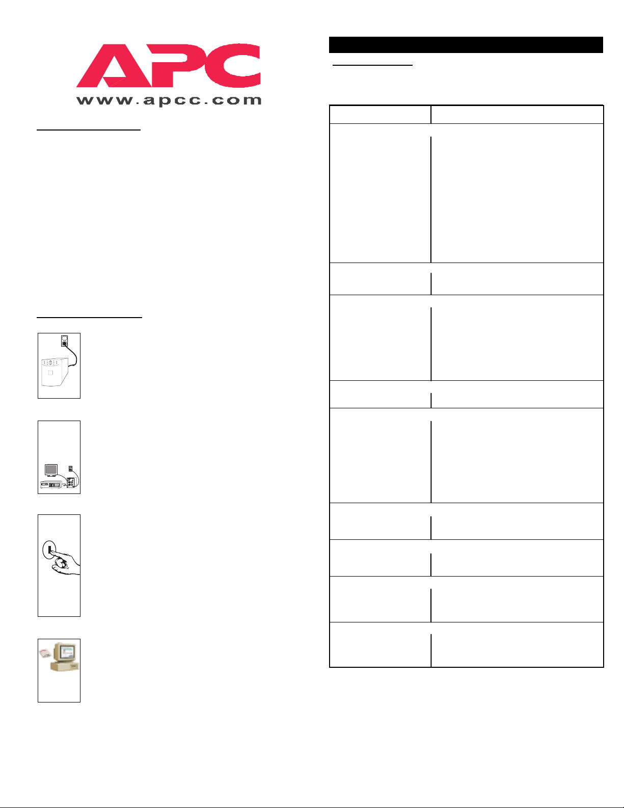
Installation and Setup
1. Install UPS
¥ Before plugging in the unit, install any SmartSlot acces-
sories. Follow the installation instructions that come with
the accessory.
¥ Plug the power cord attached to the UPS into the power
supply.
2. Connect Equipment
¥ Do not power laser printers through the UPS.
¥ Use your equipmentÕs power cords to connect to the UPS.
¥ Install PowerChute¨black communication cable between
UPS and computer.
¥ Turn on all connected equipment.
3. Turn on UPS
¥ Press the UPSÕs ON switch to turn on your UPS. This will
power-up connected equipment.
¥ The unit performs a self-test automatically when turned
on, and every two weeks thereafter.
¥ The UPS charges its battery whenever it is connected to
utility power. The battery charges fully during the first
4 hours of normal operation. Do not expect full runtime
during this initial charge period.
4. Install PowerChute
¥ For additional computer system security, install Power-
Chute¨UPS monitoring software. It provides automatic
unattended shutdown capabilities on most major network
operating systems. See the Software Installation:
Instruction Sheet for details.
Smart-UPS Quick Reference Guide -
.
Englis
¨
Smart-UPS Quick Reference Guide Ñ English
T
roubleshooting
Use the chart below to solve minor UPS installation problems. Contact APC
Technical Support Staff for assistance with complex UPS problems. See the
UserÕs Manual for a location near you.
Problem and Solution
Possible Cause
UPS will not turn on.
¥ ON button not pushed. Press the ON button once to power the UPS and
¥ UPS not connected to Check that the power cable from the UPS to the
AC power supply. power supply is securely connected at both ends.
¥ UPS input circuit breaker Reduce the load on the UPS by unplugging
tripped. equipment and reset the circuit breaker (on back
¥ Very low or no utility Check the AC power supply to the UPS with a
voltage. table lamp. If very dim, have the utility voltage
¥ Battery not connected Confirm the battery connections.
properly.
UPS will not turn off.
¥ Internal UPS fault. Do not attempt to use the UPS. Unplug the UPS
UPS operates on-battery although normal line voltage exists.
¥ UPSÕs input circuit breaker Reduce the load on the UPS by unplugging
tripped. equipment and reset the circuit breaker (on back of
¥ Very high, low, or distorted Move the UPS to a different outlet on a different circuit.
line voltage. Inexpensive Test the input voltage with the utility voltage display.
fuel powered generators If acceptable to the load, reduce the UPSÕs
can distort the voltage. sensitivity. See UserÕs Manual for procedures.
UPS beeps occasionally.
¥ Normal UPS operation. None. The UPS is protecting the load.
UPS does not provide expected backup time.
¥ The UPSÕs battery is weak Charge the battery. Batteries require recharging
due to recent outage or is after extended outages. Also, they wear faster
near the end of its when put into service often or when operated at
service life. elevated temperatures. If the battery is near the end
¥ The UPS is overloaded. Check the UPSÕs load display. Unplug less needed
Front panel indicators flash sequentially.
¥ The UPS has been shut None. The UPS will restart automatically when
down by remote control. utility power returns.
All indicators are lit and UPS emits a constant beeping.
¥ Internal UPS fault. Do not attempt to use the UPS. Turn the UPS off
All indicators are off and UPS is plugged into wall outlet.
¥ The UPS is shut down and None. The UPS will return to normal operation
the battery is discharged when the power is restored and the battery has a
from an extended outage. sufficient charge.
The replace battery light is lit.
¥ Weak batteries. Do another self test to see if it clears.
¥ Replacement batteries Confirm the battery connections.
not connected properly.
the load.
of UPS) by pressing the plunger back in.
checked.
and have it serviced immediately.
UPS) by pressing the plunger back in.
of its service life, consider replacing the battery even
if the replace battery indicator is not yet lit.
equipment, such as printers.
and have it serviced immediately.
990-4203 Revision 1 12/98
Page 3
Safety
This Safety Guide contains important instructions that should be followed during installation and maintenance of the APC equipment and batteries. It is intended for APC
customers who setup, install, relocate, or maintain APC equipment.
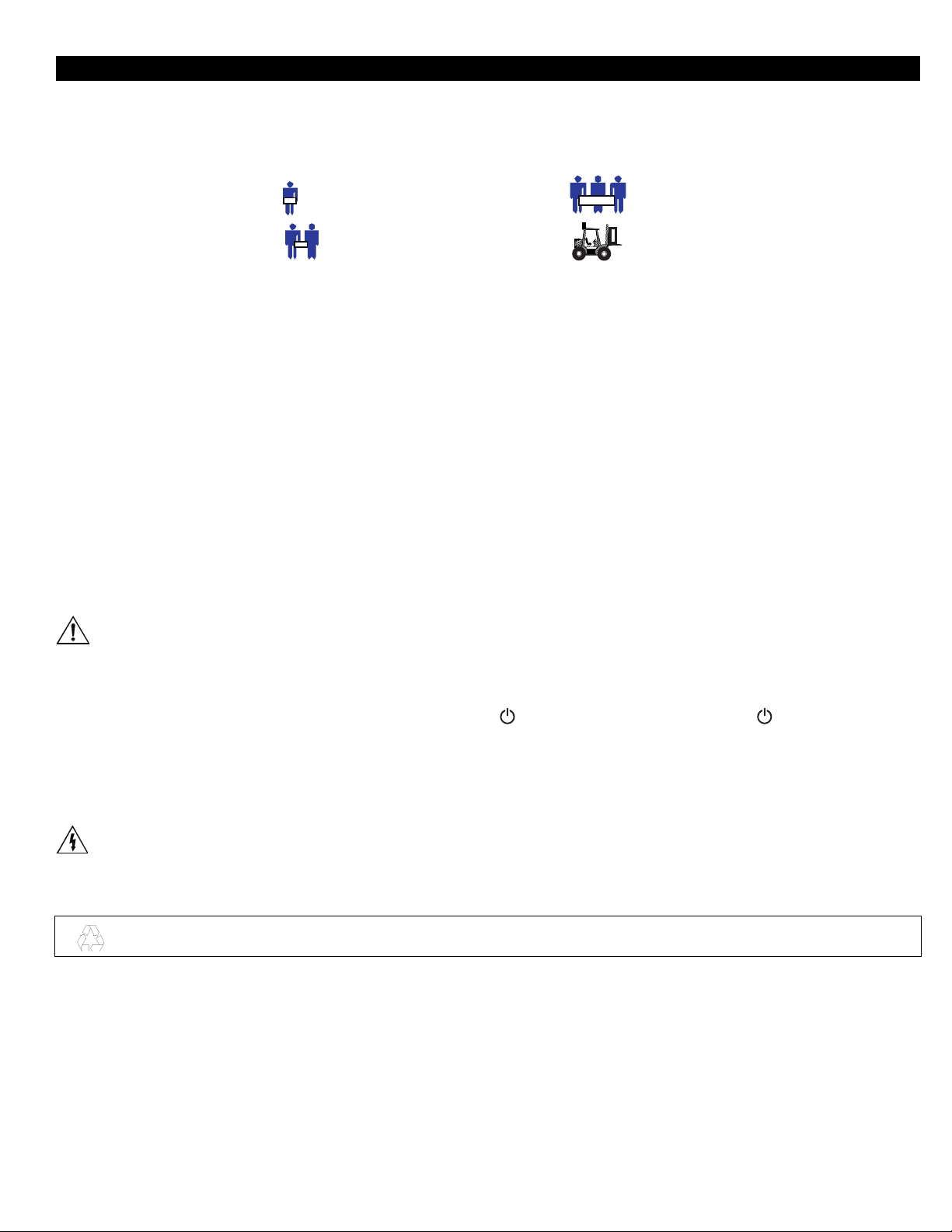
Handling Safety
• Be careful. Do not lift heavy loads without assistance.
⇒ <18 kg (<40 lb.) ⇒ 32-55 kg (70-120 lb.)
⇒ 18-32 kg (40-70 lb.) ⇒ >55 kg (>120 lb.)
• Equipment with casters is built to move on a smooth surface without any obstacles.
• Do not use a ramp inclined at more than 10°.
• This equipment is intended for installation in a temperature-controlled indoor area (see the User’s Manual for exact temperature
range), free of conductive contaminants.
Electrical Safety
• Do not work alone under hazardous conditions.
• High short circuit current through conductive materials could cause severe burns.
• A licensed electrician is required to install permanently wired equipment.
• Check that the power cord(s), plug(s), and sockets are in good condition.
• To reduce the risk of electric shock when grounding cannot be verified, disconnect the equipment from the AC power outlet before installing or connecting to
other equipment. Reconnect the power cord only after all connections are made.
• Do not handle any kind of metallic connector before the power has been removed.
• Use one hand, whenever possible, to connect or disconnect signal cables to avoid a possible shock from touching two surfaces with different electrical grounds.
• Connect the equipment to a three wire AC outlet (two poles plus ground). The receptacle must be connected to appropriate branch circuit/mains protection
(fuse or circuit breaker). Connection to any other type of receptacle may result in a shock hazard.
CAUTION! Deenergizing Safety
• If the equipment has an internal energy source (the battery), the output may be energized when the unit is not connected to an AC power outlet.
• To deenergize pluggable equipment: first press the Off button for more than one second to switch the equipment off. Next disconnect the equipment from the
AC power outlet. Finally, disconnect the battery.
• To deenergize permanently wired equipment: set the power switch to standby . Next set the AC circuit breaker to standby . Then disconnect the
batteries (including any expansion units). Finally, disconnect the AC power from the building power supply.
• Pluggable equipment includes a protective earth conductor which carries the leakage current from the load devices (computer equipment). Total leakage cur-
rent must not exceed 3.5 mA.
• Use of this equipment in life support applications where failure of this equipment can reasonably be expected to cause the failure of the life support equip-
ment or to significantly effect its safety or effectiveness is not recommended.
WARNING! Battery Safety
• This equipment contains potentially hazardous voltages. Do not attempt to disassemble the unit. The only exception is for equipment containing batteries.
Battery replacement using the procedures below is permissible. Except for the battery, the unit contains no user serviceable parts. Repairs are performed only
by factory trained service personnel.
Batteries must be recycled. Deliver the battery to an appropriate recycling facility or ship it to the supplier in the new battery’s packing material.
See the new battery instructions for more information.
• Do not dispose of batteries in a fire. The batteries may explode.
• Do not open or mutilate batteries. They contain an electrolyte which is toxic and harmful to the skin and eyes.
• To avoid personal injury due to energy hazard, remove wrist watches and jewelry such as rings when replacing the batteries. Use tools with insulated handles.
• Replace batteries with the same number and type of batteries as originally installed in the equipment.
Replacement and Recycling of Batteries
See your dealer or the User Manual for information on replacement battery kits and battery recycling.
1 990-7061A, Revision 2 12/98
Page 4
Initial Startup
Inspection
Inspect the UPS upon receipt. Notify the carrier and dealer if there is damage. The
packaging is recyclable; save it for reuse or dispose of it properly.
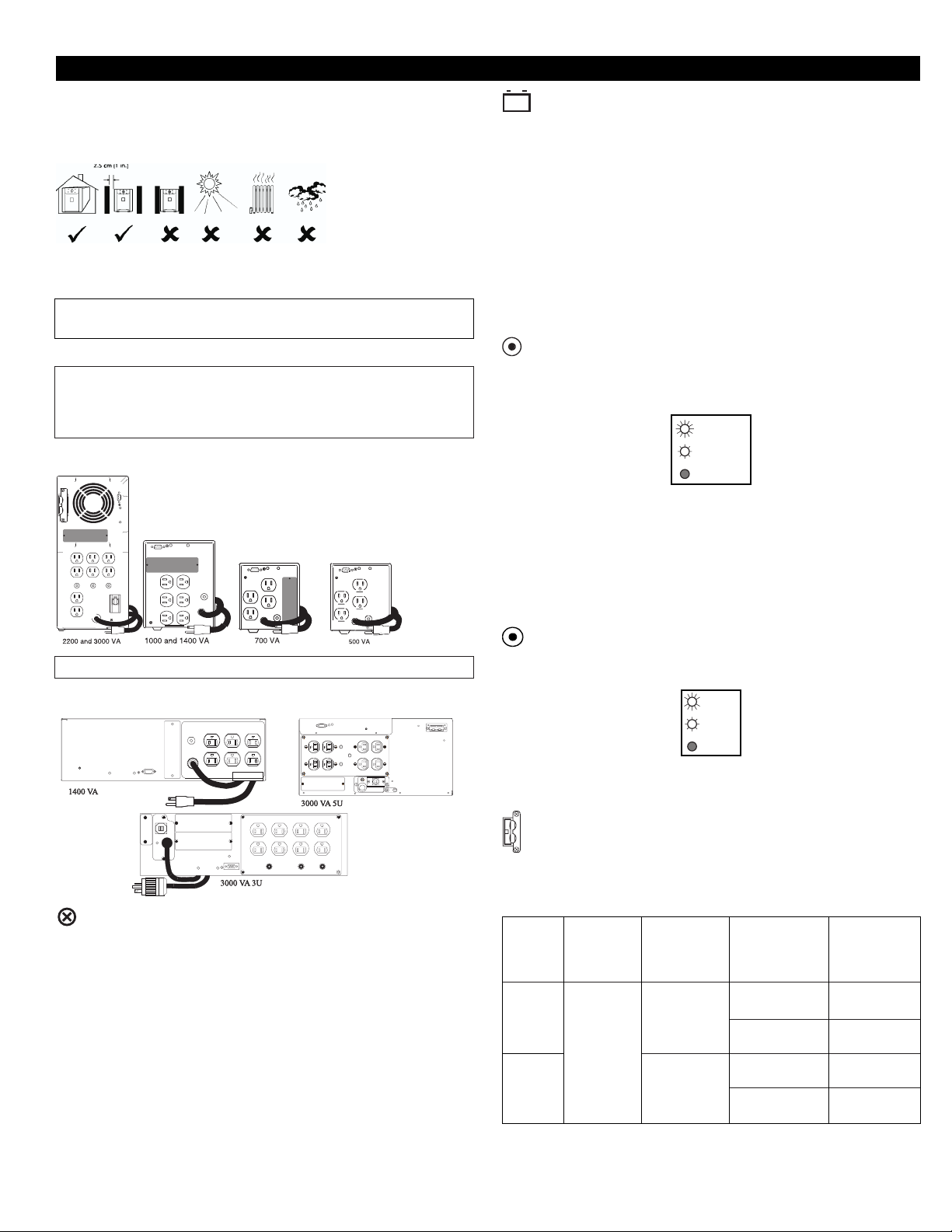
Placement
Install the UPS in a protected area that is free of excessive dust and has adequate
air flow. Do not operate the UPS where the temperature and humidity are outside
the specified limits.
Warning: Changes or modifications to this unit not expressly approved
by the party responsible for compliance could void the warranty.
Installation
To install this UPS, please follow the installation instructions in the
Smart-UPS Quick Reference Guide.
If this UPS is equipped with a SmartSlot for accessories, see the APC
Website (www.apc.co.jp) for available accessories.
Rear Views Tower Units
Charge the battery
The UPS charges its battery whenever it is connected to utility power. For best
results, charge the battery for 2.5 hours before use. It is acceptable to use the UPS
without first charging the battery, but on-battery run time may be reduced until the
battery charges.
Voltage Sensitivity
The UPS detects line voltage distortions such as spikes, notches, dips, and swells,
as well as distortions caused by operation with inexpensive fuel-powered generators. By default, the UPS reacts to distortions by transferring to on-battery operation
to protect the loads. Where power quality is poor, the UPS may frequently transfer
to on-battery operation. If the loads can operate normally under such conditions,
battery capacity and service life may be conserved by reducing the sensitivity of
the UPS.
To reduce UPS sensitivity, press the Sensitivity button on the rear panel. Use
a pointed object such as a pen to press the button. Press it once to set the UPS’s
sensitivity to reduced. Press it again to set the sensitivity to low. Press the button a
third time to reset normal sensitivity.
normal
reduced
low
When the UPS is set to normal sensitivity, the LED is brightly lit. When it is set to
reduced sensitivity, the LED is dimly lit. When it is set to low sensitivity, the LED
is off.
Note: The SU2200J does not have the battery expansion slot.
Rear Views Rack Mount Units
Connect Ground Leads to TVSS Connector (Optional)
The UPS features a TVSS connector for connecting the ground lead on transient
voltage surge-suppression (TVSS) devices such as telephone and network line
protectors. The TVSS connector provides grounding through the UPS’s power
cord ground conductor. To make a connection to the TVSS connector, loosen the
screw and connect the surge suppression device’s ground lead. Tighten the screw
to secure the lead.
Low Battery Warning Interval
By default, the low battery warning occurs when there are approximately two minutes of on-battery run time remaining. This may not be enough time to gracefully
shut down some protected computer systems.
To change the warning interval, press the rear panel Sensitivity button while
pressing and holding the front-panel on/test button. Use a pointed object such as a
pen to press the configuration button.
2 min.
5 min.
7 min.
Press the Sensitivity button once to set the low battery warning interval to approximately five minutes. Press it again to set the interval to approximately seven
minutes. Press the button a third time to reset the interval to two minutes.
Battery Pack Connector (3000 VA tower and 3000RM5U models only)
Use the battery pack connector to connect the optional external battery pack.
2200VA and 3000VA Input Power Connectors
Model Standard Maximum Available input Maximum
2200 VA
3000 VA
input power output power power power with
connector with standard connectors available
30 Amp
connector connector
2200 VA/
1600 W
2250 VA/
2250 W
20 Amp 1500 VA /
30 Amp 2200 VA /
30 Amp 2250 VA /
Hard wired 3000 VA /
1500 W
1600 W
2250 W
2250 W
2 990-7061A, Revision 2 12/98
Page 5

Rack Mount Installation
Installation Tips for Rack Mount Units
Please observe the following items when installing the Rack Mount UPS:
• The UPS comes with standard 19” (46.5 cm) rack mount brackets
installed.
• The 3000 VAmodel of the UPS is supplied with L channel supports.
These supports may be used with this model to ease installation for a 19”
rack. The L channel supports are available as an accessory for the 1400
VAmodel. Contact your dealer or the factory at the number listed under
Service for more information.
• Caution: The 3000 VA model requires two or more people to install due
to its weight.
• The UPS is not supplied with screws to attach the mounting bracket (ears)
to the rack, as the size of screw varies according to the type of rack used.
• UPSs are heavy. Select a rack location sturdy enough to handle the weight.
Try to mount the UPS near the bottom of the rack.
• Select a rack location with adequate air flow that is free from excessive
dust. Ensure that the air vents on the sides of the UPS are not blocked. Do
not operate the UPS where temperature or humidity are outside the limits
listed under Specifications.
• Caution: Remove the UPS before moving the rack.
• Two additional sets of bracket holes, shown below at asterisks (*), are
located on the sides of the UPS. These holes allow mounting the brackets
with a three inch or six inch setback. Move the mounting brackets back if
desired to optimize the esthetic or physical requirements of the rack.
• Caution: Check the rack to make sure it won’t tip after moving the
mounting brackets.
Installing the L Channel Supports on Rack Mount Units
1. Verify the contents of the kit. It contains: two adjustable-length L-channel
supports included with the 3000 VA model only, four clip nuts, eight 1032 x 1/2” flat-head screws, and eight washers. The washers are for use
with square rack holes only.
2. If the rack’s rails have threaded holes, drill out the appropriate front rail
rack holes with a 7/32” drill bit.
Note: The mounting rails do not require clips. The threaded insert
is part of the actual rail.
3. Secure the front of the support to the front cabinet rack using two 10-32 x
1/2” flat-head screws (shown in blow-up below). Note that the front ear of
the L-channel support has a square cutout on the mounting ear
rear ear has no cutout
er under the head of each screw.
4. Loosen the two 10-32 x 5/16” pan-head screws that lock together the two
halves of the L-channel support
the rear until it contacts the rear rack of the cabinet. If the rack uses
threaded holes, drill out the appropriate rear rail rack holes with a 7/32”
drill bit (see Step 2).
5. Secure the rear of the support to the rear cabinet rack using two 10-32 x
1/2” flat-head screws (see full picture below). For cabinets with square rack
holes, use a washer under the head of each screw (see blow-up below).
6. Securely tighten the two 10-32 x 5/16” pan-head screws that lock together
the halves of the L-channel support
7. Repeat steps 2 through 5 to install the other L-channel support.
➋. For cabinets with square rack holes, use a wash-
➌. Slide the outer half of the support to
➌.
➊, and the
Rack Mount Options
Accessory receptacle plates are available for the 3000 VA model. These plates
offer different receptacle configurations and hard wire installation. Contact your
dealer or the factory at the number listed below in Service.
Input Hardwire Instructions
This function must be performed by qualified personnel only
8. Mounting clips are required for the mounting ears on the UPS. Use
the enclosed template (990-0195) to install the clips for the UPS ears.
9. Slide the UPS onto the L-channel supports and use rack hardware to
secure the UPS mounting ears to the rack rails.
Note:
1. Disconnect and remove the input plug.
2. Remove additional length of outer jacket from cable to ease wire installation.
3. Install cable into electrical box that supplies 30 Amps at 100 Volts. Use a suitable cable clamp.
4. Connect black and white wires to 100V source. (White is connected to neutral - if one of the connectors is identified as neutral.)
5. Connect green wire to ground wire (if present). Otherwise, connect to the metal electrical box.
3 990-7061A, Revision 2 12/98
Page 6

Operating Instructions
Switch On Ñ Switch Off
With the UPS plugged in, press and release the large upper on/test button to
supply power to the loads. The loads are immediately powered while the UPS
beeps and performs a self-test.
Press and release the small, lower off button to turn off power to the loads. It
may be convenient to use the UPS as a master on/off switch for the protected
equipment.
Note: Whenever the UPS is plugged in and utility voltage is present, the charger
maintains battery charge.
The on-line LED illuminates when the UPS is supplying utility power to the
loads.
On Battery
During on-battery operation, the on-battery LED illuminates and the UPS sounds
an audible alarm consisting of four beeps every 30 seconds. The alarm stops when
the UPS returns to on-line operation.
Battery Charge Bar Graph
The 5-LED display on the right of the front panel shows the present charge of the
UPS’s battery as a percentage of the battery’s capacity. When all five LEDs light,
the battery is fully charged. The top LED goes out whenever the battery is not
100% charged. When the lowest LED is flashing, the battery can supply less than
two minutes of run time for the load.
Shutdown Mode
In shutdown mode the UPS stops supplying power to the load, waiting for the
return of utility power. If there is no utility power present, external devices (e.g.,
servers) connected to the computer interface or the accessory slot can command
the UPS to shut down. This is normally done to preserve battery capacity after the
graceful shutdown of protected servers. The UPS will scroll the front panel indicators sequentially in shutdown mode.
Replace Battery
If the battery fails a self-test, the UPS emits short beeps for one minute and the
replace battery LED illuminates. The UPS repeats the alarm every five hours. Perform the self-test procedure to confirm replace battery conditions. The alarm stops
when the battery passes the self-test.
Load Bar Graph
The 5-LED display on the left of the front panel represents the power drawn from
the UPS as a percentage of total capacity. For example, if three LEDs are lit, the
load is drawing between 50% and 67% of the UPS’s capacity. If all five LEDs
light, thoroughly test your complete system to make sure that the UPS will not
become overloaded.
Overload
When the UPS is overloaded (when the connected loads exceed the maximum
specified in the “maximum load” section under Specifications), the overload LED
comes on and the UPS emits a sustained tone. The alarm remains on until the
overload is removed. Disconnect nonessential load equipment from the UPS to
eliminate the overload.
Self-test
The UPS performs a self-test automatically when turned on, and every two weeks
thereafter (by default). Automatic self-test eases maintenance requirements by
eliminating the need for periodic manual self-tests.
During the self-test, the UPS briefly operates the loads on-battery. If the UPS
passes the self-test, it returns to on-line operation.
If the UPS fails the self-test it immediately returns to on-line operation and
lights the replace battery LED.
The loads are not affected by a failed test. Recharge the battery overnight and
perform the self-test again. If the replace battery LED is still on, replace the
battery using the Replacing the Battery procedure.
SmartTrim
The SmartTrim LED comes on to indicate that the UPS is compensating for a high
voltage.
SmartBoost
The SmartBoost LED comes on to indicate that the UPS is compensating for a low
voltage.
Low Battery
When the UPS is operating on-battery and the energy reserve of the battery runs
low, the UPS beeps continuously until the UPS shuts down from battery exhaustion or returns to on-line operation.
Cold Start
When the UPS is off and there is no utility power, use the cold start feature to
apply power to the loads from the UPS’s battery.
Note: Cold start is not a normal condition.
• Press and hold the on/test button until the UPS beeps.
• Release the on/test button during the beep and the loads are powered within
4 seconds.
.
Utility Voltage Bar Graph
This UPS has a diagnostic feature that displays the utility voltage. With the UPS
plugged into the normal utility power, press and hold the on/test button to see the
utility voltage bar graph display. After approximately four seconds the 5-LED
display on the right of the front panel shows the utility input voltage. Refer to the
figure below for the voltage reading.
The display indicates that the voltage is between the displayed value from the list
and the next higher value. For example, with three LEDs lit, the input voltage is
between 101 and 109 VAC.
If no LEDs come on and the UPS is plugged into a working AC power outlet, the
line voltage is extremely low.
If all five LEDs come on, the line voltage is extremely high and should be checked
by an electrician.
Note: The UPS starts a self-test as a part of this procedure.
The self-test does not affect the voltage display.
The utility voltage bar graph has a margin of error of ± 4%.
4 990-7061A, Revision 2 12/98
Page 7

Storage
Storage Conditions
Store the UPS covered and upright in a cool, dry location, with its battery fully
charged. Before storing, charge the UPS for at least 2 hours. Remove any accessories in the accessory slot and disconnect any cables connected to the computer
interface port to avoid unnecessarily draining the battery.
Extended storage
At -15 to +30 °C (+5 to +86 °F), charge the UPS’s battery every 6 months.
At +30 to +45 °C (+86 to +113 °F), charge the UPS’s battery every 3 months.
Replacing the Battery
This UPS has an easy to replace hot-swappable battery. Battery replacement is a safe procedure, isolated from electrical hazards. You may leave the UPS and loads on for
the following procedure. See your dealer or call the number in this manual for information on replacement battery cartridges.
Note: Please read the cautions in the APC Safety Guide.
Once the battery is disconnected, the loads are not protected from power outages.
Model # Replacement Battery Cartridge (RBC) #
500 RBC20
700 RBC5
1000 RBC6
1400 RBC7
2200 RBC11
3000 RBC11
1400RM RBC8
3000RM (3U) RBC12
3000RM (5U) RBC11
Battery Replacement Procedure — 2200 - 3000 VA Tower Units
1. Grasp the top edge of the bottom front cover and tilt it out.
2. Unhook the bottom section of the front cover from the chassis and set it aside.
3. Use a flat-blade screwdriver or a coin to remove the two battery door screws and open the door.
4. Notice the red and black wires at the top of the battery housing. Gently but firmly pull the wires to disconnect the gray connector plug from
the UPS.
5. Pull the front battery out of the UPS. Remove the foam spacer and set it aside.
Note: Be careful removing the batteries — they are heavy.
6. Disconnect and remove the battery pack by repeating steps 4 and 5.
7. Replace the back battery. Reconnect the battery by pressing the gray connector into the plug at the top of the battery housing. Replace the
foam spacer. Replace the front battery into the UPS and reconnect.
Note: Small sparks at the battery connectors are normal during connection.
8. Close the battery door, replace the screws, and replace the lower front cover.
9. Batteries must be recycled. Deliver the battery to an appropriate recycling facility or ship it to the supplier in the new battery’s packing
material. See the new battery instructions for more information.
5 990-7061A, Revision 2 12/98
Page 8

1400 VA
700-1400 VA
700-1400 VA
500 VA
Battery Replacement Procedure – 500 - 1400 VA Tower Units
1. Grasp the top of the front cover and tilt it out and down.
2. Unhook the bottom of the cover from the chassis and lift it upward to expose the battery door. Be careful not to strain the
ribbon cable. Do not touch the exposed printed circuit board.
3. Fold the front cover on top of the UPS as shown.
4. Use a flat-blade screwdriver or a coin to remove the two battery door screws and open the door.
5. For the 700 through 1400 models, grasp the tab and gently pull the battery out of the UPS. For the 500 model, grasp the sides
of the battery and gently pull the battery out of the UPS.
6. Disconnect the battery leads.
• For the 500 through 1000 VAmodels, loosen the connectors by gently wiggling them while pulling straight back from
the battery connector.
• For the 1400 VA model, pull the two gray couplers apart to disconnect the battery.
7. Connect the battery leads to the new battery.
Note: Small sparks at the battery connectors are normal during connection.
500-1000 VA
• For the 500 through 1000 VAmodels, connect the red wire to the positive (+) terminal and the black wire to the
negative (–) terminal.
• For the 1400 VAmodel, connect the gray battery coupler to the UPS’s coupler, slide the battery into the UPS, close
the battery door, replace the battery compartment screws, and replace the front cover.
8. Batteries must be recycled. Deliver the battery to an appropriate recycling facility or ship it to the supplier in the new
battery’s packing material. See the new battery instructions for more information.
Battery Replacement Procedure – 1400 VA Rack Mount Units
1. Reach into the finger pull and open the front cover. Swing the cover open as shown.
2. Unhook the side of the cover from the chassis and lift it away to expose the battery door.
3. Use a flat-blade or Phillips screwdriver or a coin to remove the two battery door screws and open the door.
4. Grasp the tab and gently pull the battery out of the UPS.
5. Disconnect the battery leads. Loosen the connectors by gently wiggling them while pulling straight back from the battery connector.
6. Connect the battery leads to the new battery. Connect the red wire to the positive (+) terminal and the black wire to the negative (–) terminal.
7. Slide the battery into the UPS.
8. Close the battery door, replace the battery compartment screws, and replace the front cover.
Notes:
Be careful removing the batteries – they are heavy.
Small sparks at the battery connectors are normal during connection.
9. Batteries must be recycled. Deliver the battery to an appropriate recycling facility or ship it to the supplier in the new batery’s
packing material. See the new battery instructions for more information.
6 990-7061A, Revision 2 12/98
Page 9

Battery Replacement Procedure – 3000 VA Rack Mount Unit
1. Reach into the finger pull and open the front cover. Swing the cover open as shown.
2. Unhook the side of the cover from the chassis and lift it away to expose the battery door.
3. Use a flat-blade screwdriver or a coin to remove the two battery door screws and open the door.
4. Grip the white cord on the front set of batteries and pull firmly to disconnect the connector from the battery compartment and
remove the batteries.
5. Set aside the foam spacer located between the batteries, if there is one.
6. Reach into the battery compartment and grasp the white cord on the other battery connector. Pull firmly to disconnect the
connector and remove the rear set of batteries.
7. Slide the rear set of new batteries into the unit. Hold the connector down below the top of the batteries and toward the door,
otherwise the assembly will not fit. Guide the connector over the top of the batteries and press firmly to connect it to the rear
connector of the battery compartment.
8. Set the foam spacer against the rear batteries to prevent the wires from being pinched.
9. Slide the front set of batteries in, then guide the connector over the batteries and press firmly to connect it to the front connector of the battery compartment.
10.Close the battery door, replace the screws, and replace the front cover.
11. Batteries must be recycled. Deliver the battery to an appropriate recycling facility or ship it to the supplier in the new bat-
tery’s packing material. See the new battery instructions for more information.
User Configuration Items
Automatic Self-Test
UPS ID
Date of Last Battery Replacement
Minimum Capacity Before Return from
Shutdown
Sensitivity
Duration of Low Battery Warning
Alarm Delay After Line Fail
Shutdown Delay
Synchronized Turn-on Delay
High Transfer Point
Low Transfer Point
Function
Note: Setting these items requires optional software or hardware.
Factory Default
Every 14 days
(336 hours)
UPS_IDEN
Manufacture Date
0 percent
Normal
2 minutes
5 second delay
20 seconds
0 seconds
110 Vac
90 Vac
User Selectable Choices
Every 7 days (168 hours), On Startup
Only, No Self-Test
Up to eight characters to define the
UPS.
Date of Battery Replacement
15, 50, 90 percent
Reduced, Low
5, 7, 10 minutes
30 second delay, At Low Battery
Condition, No Alarm
180, 300, 600 seconds
60, 180, 300 seconds
108, 112, 114 Vac
81, 85, 92 Vac
Sets the interval at which the UPS will
execute a self-test.
Use this field to uniquely identify the UPS for
network management purposes.
Reset this date on battery replacement.
The UPS will charge its batteries to the
specified percentage before return from
a shutdown.
Set lower than normal sensitivity to avoid
lowered battery capacity and service life in
situations where the load can tolerate minor
power disturbances.
Sets the time before shutdown at which the
UPS issues a low battery warning. Set higher
than the default only if the OS needs the time
for graceful shutdown.
To avoid alarms for minor power glitches, set
the alarm delay.
Sets the interval between when the UPS
receives a shutdown command and when
shutdown occurs.
To avoid branch circuit overload, the UPS
will wait the specified time after the return of
utility power before turn-on.
To avoid unnecessary battery usage, set the
High Transfer Point higher if the utility voltage is chronically high and the load is known
to work well under this condition.
Set the Low Transfer Point lower if the utility
voltage is chronically low and the load can
tolerate this condition.
Description
7 990-7061A, Revision 2 12/98
Page 10

How to Determine On-Battery Run Time
UPS battery life differs based on usage and environment. It is recommended that the battery/batteries be changed once every two years.
Typical On-Battery Run Time Versus Load, In Minutes
Model 500 700 1000 1400 1400RM 2200 3000 3000 3000RM
30W 50 VA 110 140 150 251 192 366 297 640 297
45W 75 VA 85 113 125 199 152 309 258 557 258
60W 100 VA 60 85 100 163 125 268 228 491 228
95W 150 VA 36 55 75 118 90 209 183 394 183
125W 200 VA 23 38 58 90 69 170 152 328 152
155W 250 VA 17 26 44 71 54 142 128 281 128
185W 300 VA 15 20 36 57 44 121 110 245 110
215W 350 VA 11 17 28 47 36 104 96 216 96
250W 400 VA 9 14 24 39 30 91 84 193 84
280W 450 VA 8 11 20 33 25 80 75 174 75
320W 500 VA 7 9 18 29 22 71 67 157 67
350W 550 VA - 8 15 25 19 64 60 143 60
385W 600 VA - 6 13 21 16 57 54 131 54
450W 700 VA - 5 11 18 13 46 44 112 44
515W 800 VA - - 9 15 11 38 36 96 36
580W 900 VA - - 7 12 9 32 31 84 31
670W 1000 VA - - 6 11 8 27 26 73 26
830W 1200 VA - - - 8 6 21 20 58 20
950W 1400 VA - - - 7 5 17 16 46 16
1170W 1600 VA - - - - 14 13 37 13
1460W 2000 VA - - - - 10 10 26 10
1600W 2200 VA - - - - 8 8 22 8
1850W 2500 VA - - - - - 7 18 7
2250W 3000 VA - - - - - 5 13 5
Note:
w/ext. batt.
Specifications
SU500J SU700J SU1000J SU1400J SU1400RMJ SU2200J SU3000J SU3000RMJ SU3000RMJ
Acceptable input voltage 0 - 160 VAC
Output voltage 90-110 VAC
Input Protection Resettable circuit breaker
Frequency limits (on-line operation) 50 or 60 Hz, ± 5%
Transfer time 2 ms typical, 4 ms maximum
Maximum load* 500 VA 700 VA 1000 VA 1400 VA 1400 VA 2200 VA 3000 VA
On-battery output voltage 100 VAC
On-battery frequency 50 or 60 Hz, ±0.1 Hz; unless synchronized to utility during brownout.
On-battery waveshape Low-distortion sine wave
Protection Overcurrent and short-circuit protected, latching shutdown on overload.
Noise Filter Normal and common mode EMI/RFI suppression, 100 kHz to 10 MHz
Battery type Spill proof, maintenance free, sealed lead-acid
Typical battery life Life varies; typical 3-6 years, depending on number of discharge cycles and ambient temperature
Typical recharge time 2 to 5 hours from total discharge
Operating temperature 0 to +40 ºC (+32 to +104 ºF)
Storage temperature -15 to +45 ºC (+5 to +113 ºF)
Operating and storage relative humidity 50 to 95%, non-condensing
Operating elevation 0 to +3,000 m (0 to +10,000 ft)
Storage elevation 0 to +15,000 m (0 to +50,000 ft)
Electromagnetic immunity IEC 801-2 level IV, 801-3 level III, 801-4 level IV
Audible noise in dBA at 1 m (3 ft) <41 <45 <53
Size (H x W x D) 15.8 x 13.7 x 35.8 cm 21.6 x 17 x 43.9 cm 13 x 48.3 x 38.1 cm 43.2 x 19.6 x 54.6 cm 13 x 48.3 x 22.2 x 48.3 x
Weight - net (shipping) 11.6 13.1 18 24.1 25 (27.6) kg 51 (60) kg 55.8 50.9 (60) kg 58.5
Safety approvals Listed to UL 1778
EMC verification VCCI Class 2 VCCI Class 1
320 W 450 W 670 W 950 W 950 W 1600 W 2250 W
(6.2 x 5.4 x 14.1 in.) (8.5 x 6.7 x 17.3 in.) (5.22 x 19 x 15 in) (17.0 x 7.7 x 21.5 in.) 66 cm 50.8 cm
(12.9) kg (14.5) kg (20.8) kg (26.1) kg 55 (61) lb. 112.3 (64.4) kg 112 (132) lb. (65.8) kg
25.5 29 41.5 53 (132.3) lb. 123 129 (145) lb.
(28.5) lb. (32) lb. (46) lb. (57.5) lb. (142)lb.
• Maximum load refers to either maximum VA or maximum W values as listed.
(3U) (5U)
(5.22 x 19 x (8.72 x 19 x
26 inches) 20 inches)
8 990-7061A, Revision 2 12/98
Page 11

Service
If the UPS requires service do not return it to the dealer!
Follow these steps:
1. Use the Troubleshooting section of the Quick Reference Guide to eliminate common problems.
2. Verify that no circuit breakers are tripped. A tripped circuit breaker is the most common UPS problem!
3. If the problem persists, call customer service or visit the APC Internet Website (www.apc.co.jp).
• Note the model number of the UPS, the serial number, and the date purchased. A technician will ask you to describe the problem and try to solve it
over the phone, if possible. If this is not possible the technician will issue a Return Merchandise Authorization Number (RMA#).
• If the UPS is under warranty, repairs are free. If not, there is a repair charge.
4. Pack the UPS in its original packaging. If the original packing is not available, ask customer service about obtaining a new set.
• Pack the UPS properly to avoid damage in transit. Never use Styrofoam beads for packaging. Damage sustained in transit is not covered under
warranty.
• Include a letter with your name, RMA#, address, copy of the sales receipt, description of the trouble, your daytime phone number, and a check
(if necessary).
5. Mark the RMA# on the outside of the package.
6. Return the UPS by insured, prepaid carrier to the address given to you by Customer Service.
APC Japan Contact Information
Japan……….…………….03-5434-2021
Internet and
Customer
E-mail: jsupport@apcc.com
Support
Address:
APC Japan, Inc.
BR Gotanda Bldg. 7F
2-30-4 Nishi-gotanda, Shinagawa-ku
Tokyo 141-0031
Limited Warranty
American Power Conversion (APC) warrants its products to be free from defects in materials and workmanship for a period of two years from the date of purchase. Its
obligation under this warranty is limited to repairing or replacing, at its own sole option, any such defective products. To obtain service under warranty you must obtain a
Returned Material Authorization (RMA) number from customer support (see the Service section of the User’s Manual). Products must be returned with transportation
charges prepaid and must be accompanied by a brief description of the problem encountered and proof of date and place of purchase. This warranty does not apply to
equipment which has been damaged by accident, negligence, or misapplication or has been altered or modified in any way. This warranty applies only to the original
purchaser who must have properly registered the product within 10 days of purchase.
EXCEPT AS PROVIDED HEREIN, AMERICAN POWER CONVERSION MAKES NO WARRANTIES, EXPRESS OR IMPLIED, INCLUDING WARRANTIES OF
MERCHANTABILITY AND FITNESS FOR A PARTICULAR PURPOSE. Some states do not permit limitation or exclusion of implied warranties; therefore, the aforesaid
limitation(s) or exclusion(s) may not apply to the purchaser.
http://www.apc.co.jp
EXCEPT AS PROVIDED ABOVE, IN NO EVENT WILLAPC BE LIABLE FOR DIRECT, INDIRECT, SPECIAL, INCIDENTAL, OR CONSEQUENTIAL DAMAGES
ARISING OUT OF THE USE OF THIS PRODUCT, EVEN IF ADVISED OF THE POSSIBILITY OF SUCH DAMAGE. Specifically, APC is not liable for any costs,
such as lost profits or revenue, loss of equipment, loss of use of equipment, loss of software, loss of data, costs of substitutes, claims by third parties, or otherwise.
9 990-7061A, Revision 2 12/98
 Loading...