

Page 1

ProRack – House (H1020)
OWNER’S MANUAL
APB-DynaSonics, Inc.
20 West End Road
Totowa, New Jersey, 07512, U.S.A.
Tel: 973-785-1101
Fax: 973-785-1105
Web: www.apb-dynasonics.com
Page 2

Page 3

IMPORTANT SAFTEY INSTRUCTIONS
CAUTION:
PLEASE READ AND OBSERVE ALL WARNINGS AND INSTRUCTIONS IN THIS INSTALLATION AND
OPERATING GUIDE AND THOSE MARKED ON THE UNIT. RETAIN THIS GUIDE FOR FUTURE REFERENCE.
This unit has been designed and manufactured to assure personal safety. Improper use can result in electric shock or fire hazard. The
safeguards incorporated in this unit will protect you if you observe the following procedures for installation, use, and servicing.
This unit does not contain any parts that can be repaired by the user.
DO NOT REMOVE ANY COVERS OR SUB-ASSEMBLIES, OR YOU MAY BE EXPOSED TO DANGEROUS VOLTAGES. REFER SERVICING
TO QUALIFIED SERVICE PERSONNEL ONLY.
• Read these instructions. – All of these safety and operating instructions should be read before this product is operated
• Keep these Instructions. – The safety, operating and use instructions should be retained for further reference.
• Heed all warnings. – All warnings on the product and in the operating instructions should be adhered to.
• Follow all instructions. - All operating and use instructions should be followed.
• Do not defeat the safety purpose of the polarized or grounding-type plug. A polarized plug has two blades with one wider
than the other. A grounding type plug has two blades and a third grounding prong. The wide blade or the third prong is
provided for your safety. If the prong does not fit into your outlet, consult an electrician of the obsolete outlet.
• Do not use this apparatus near or water. – Do not expose apparatus to dripping or splashing and ensure that no objects
filled with liquids, such as vases, glasses or cups are placed on this apparatus. Do not operate on or near wet surfaces
such as swimming pools and do not expose to rain.
• Clean only with dry cloth. – Unplug the product from the wall outlet before cleaning. Do not use liquid cleaners.
• Do not block ventilation openings. Install in accordance with manufacturers instructions. – Slots and openings in the
assembly are provided for ventilation, to ensure reliable operation of the product, and to protect from overheating. Care
should be taken never to block these openings in any operating situation.
• Do not install near any heat source such as radiators, heat registers, stoves, or other apparatus that produce heat.
• Protect the power cord from being walked upon or pinched, particularly at the plugs, convenience receptacles, and the
point where they exit from the unit.
• Only use attachments/accessories specified by the manufacturer.
• Use only the cart, stand, tripod, bracket, or table specified by the manufacturer, or sold with the apparatus. When a cart is
used, use caution when moving the cart/apparatus combination to avoid injury from tip-over.
• Unplug this apparatus during lightning storms or when unused for long period of times.
• Refer all servicing to qualified service personnel. Service is required when the apparatus has been damaged in any way,
such as power-supply cord or plug damaged, liquid has bee spilled or objects have fallen into the apparatus, the
apparatus has been exposed to rain or moisture, does not operate normally, or has been dropped.
• To completely disconnect mains power from this apparatus, the power supply cord must be unplugged.
• Check AC power source for correct voltage and sufficient current capacity.
• Unplug the unit from AC mains before moving, servicing, or cleaning.
• Do not use frayed or damaged power cords or connectors.
• Do not place the unit on an unstable surface.
• Do not operate and immediately unplug equipment from AC mains if liquid has entered the unit.
• Do not plug unit into AC mains if it has physically been damaged in any way.
• Secure and protect ALL cabling to and from the units to prevent they being walled on, pinched, or pulled.
• Do not install the unit in areas of high electromagnetic or RF fields.
• Observe proper procedures for lifting and moving this unit as its weight and size requires that more than a single person be
employed in these operations.
• Should the unit be damaged in any way or contaminated with liquid, have the unit inspected and serviced by qualified
service personnel.
• This unit contains no user serviceable parts. All servicing must be performed by a qualified service engineer or through
APB-DynaSonics or its qualified dealer.
• Operate in accordance with U.S. Governments’ Occupational and Health Administration (OSHA) requirements,
specifications, suggestions and regulations or those of any other local governing requirements where the equipment is to
be used or serviced.
3
Page 4

YOUR PRORACK MIXER
Congratulations on your purchase of one of the finest live performance professional audio mixers manufactured in the United States.
Please take a moment to review this manual. It will insure a better understanding of the operation of this mixer and may open up new
possibilities into how you use this product.
In addition to the hard copy of this manual, it will appear within our web site www.apb-dynasonics.com with the latest updates as
well as new supplemental information. We suggest that you occasionally check our web site for additional information about your
mixer as well as for new product releases and news from APB-DynaSonics.
Should you have any questions or comments about this or any other APB
product, please do not hesitate to contact us at:
Tel: 973-785-1101 Fax: 973-785-1105
e-mail: [email protected]
Manual Scope
This manual is not intended to teach you how to mix or how to set up a complete sound system. Should you be looking for such
information, May we suggest that you do a search for “Pro Audio Books” on the internet, or attend one of the many fine Recording
Schools that may be available to you. Many of these schools offer courses in Live Performance associated subjects as well as basic
mixing techniques.
One of the best sources of teaching the technical aspect of system design and operation is through the Syn-Aud-Con organization:
Synergetic Audio Concepts, Inc., 8780 Rufing Road Greenville, IN, 47124 – USA
Tel: 800-796-2831 Fax : 812-923-3610 For calls outside of the US: 812.923.0174
Email: [email protected]
www.synaudcon.com
4
Page 5

INDEX
OVERVIEW
FRONT PANEL................................................................................................................................................................................................. 6
REAR PANEL ....................................................................................................................................................................................................7
BLOCK DIAGRAM.......................................................................................................................................................................................... 8-9
MONO INPUT CHANNELS
PREAMP............................................................................................................................................................................................................. 10
EQUALIZATION.............................................................................................................................................................................................. 11
AUXILIARY SENDS........................................................................................................................................................................................ 12
BUS ASSIGNMENT AND PAN ................................................................................................................................................................. 13
MUTE, PFL AND LEVEL CONTROL ........................................................................................................................................................ 13
REAR PANEL CONNECTORS ....................................................................................................................................................................14
DUAL-MONO / STEREO INPUT CHANNELS
PREAMP............................................................................................................................................................................................................. 15
DUAL MONO / STEREO MODE SELECTION ................................................................................................................................... 15
EQUALIZATION ............................................................................................................................................................................................. 16
AUXILIARY SENDS ....................................................................................................................................................................................... 17
BUS ASSIGNMENT AND BALANCE ...................................................................................................................................................... 18
MUTE, PFL AND LEVEL CONTROL ....................................................................................................................................................... 18
REAR PANEL CONNECTORS ................................................................................................................................................................... 19
MASTER SECTION
GROUP CONTROLS ..................................................................................................................................................................................... 20
GROUP REAR PANEL CONNECTORS .................................................................................................................................................. 21
AUXILIARY CONTROLS .............................................................................................................................................................................22
AUXILIARY REAR PANEL CONNECTORS .......................................................................................................................................... 23
MAIN BUS CONTROLS ............................................................................................................................................................................... 24
MAIN BUS REAR PANEL CONNECTORS ............................................................................................................................................ 25
HEADPHONES AND MONITORING ..................................................................................................................................................... 26
MONITOR REAR PANEL CONNECTORS ............................................................................................................................................ 27
SOLO LINKING SYSTEM............................................................................................................................................................................. 27
LAMP AND DIMMER SYSTEM ................................................................................................................................................................ 28
GENERAL INFO
POWER SUPPLY ............................................................................................................................................................................................ 29
DIMENSIONS & MOUNTING ................................................................................................................................................................... 30
INTERCONNECTING..................................................................................................................................................................................... 31
TRACK SHEETS ....................................................................................................................................................................................... 33-35
SPECIFICATIONS ..........................................................................................................................................................................................37
5
Page 6
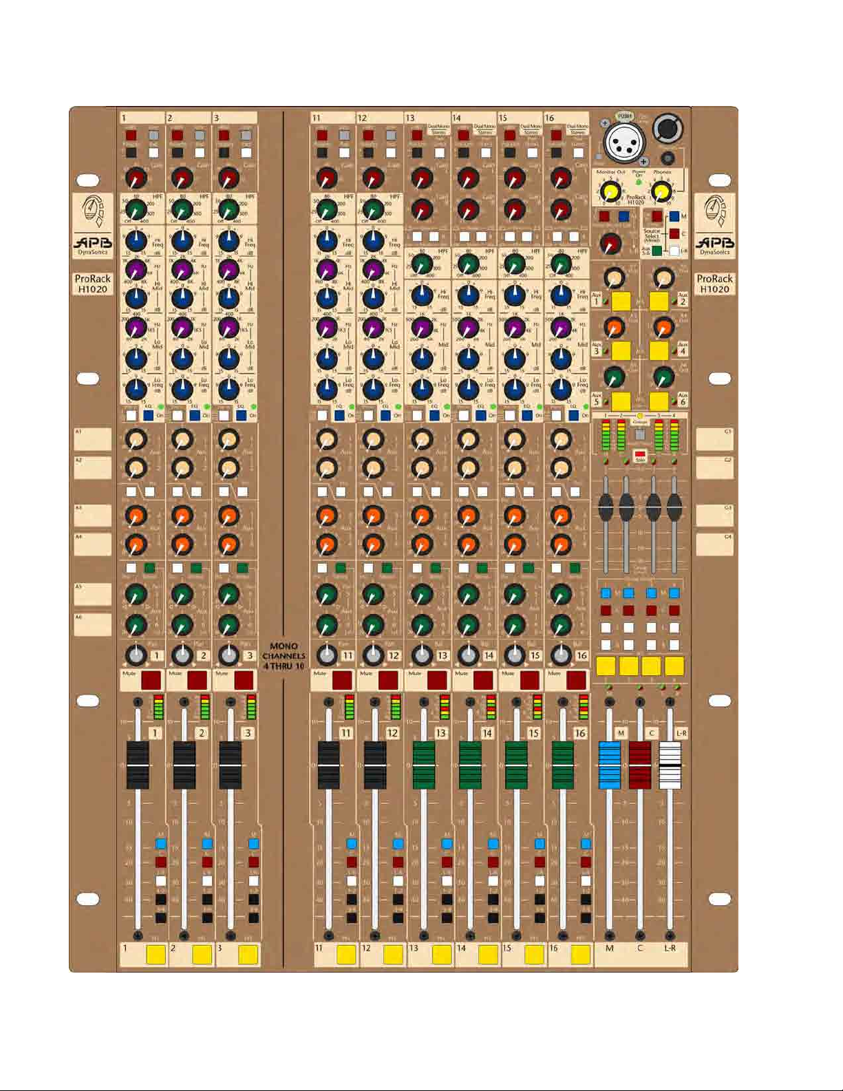
Front Panel Overview
6
Page 7
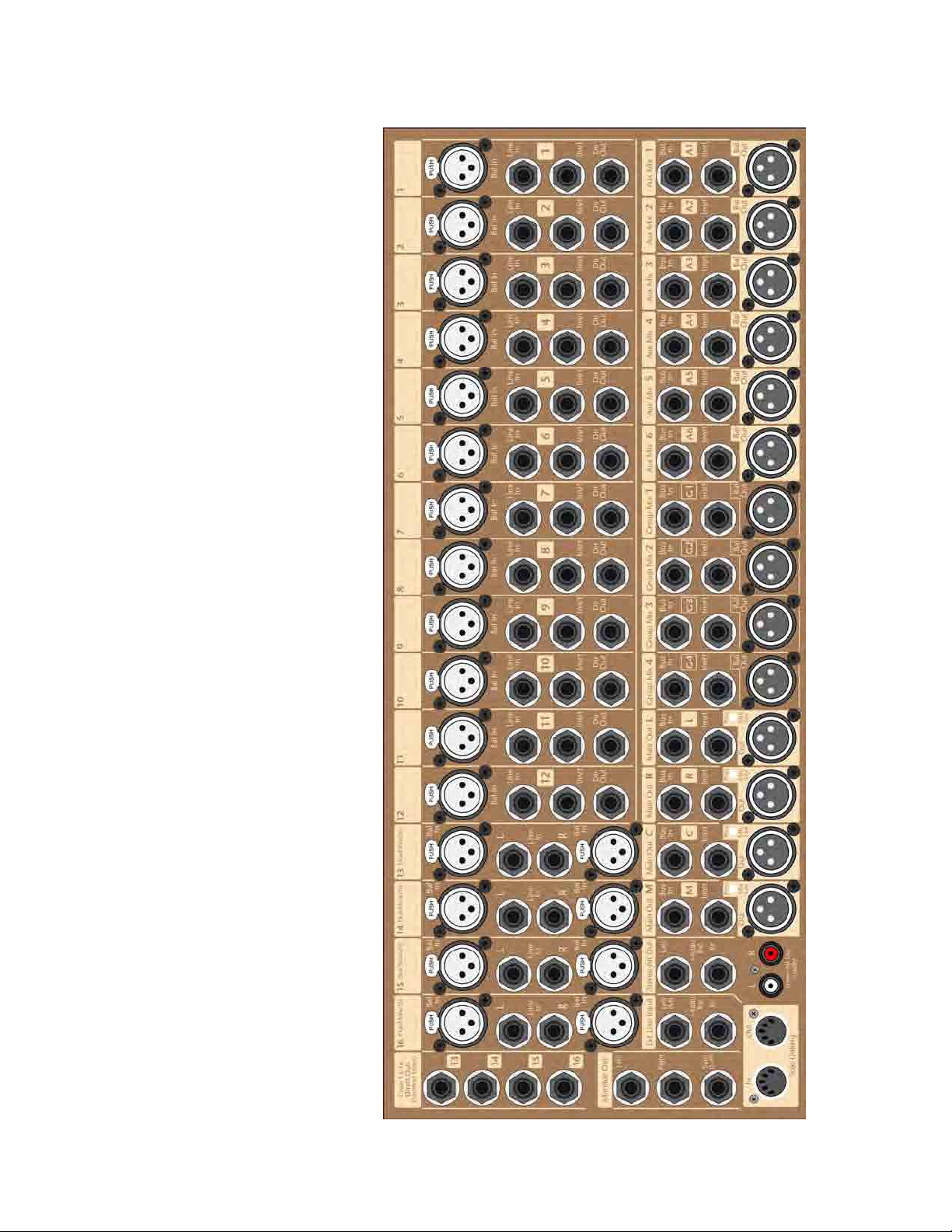
Rear Panel Overview
7
Page 8
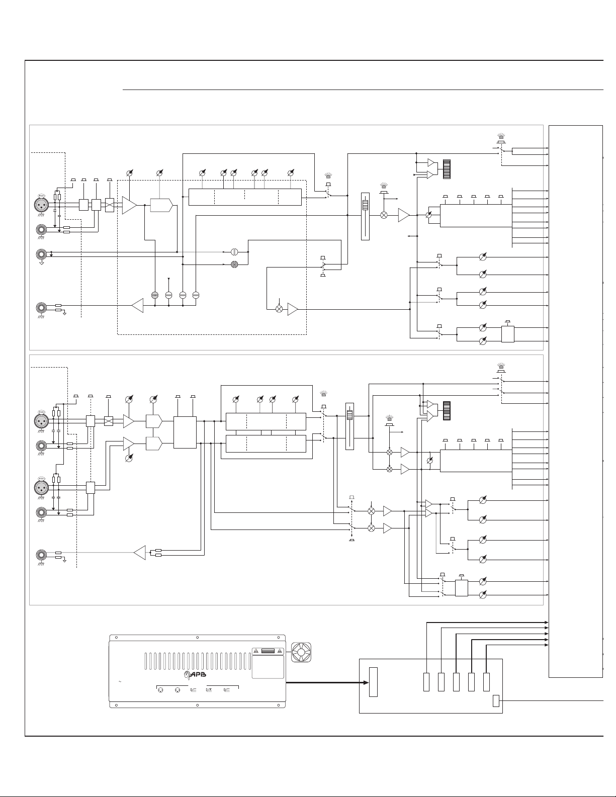
ProRack-FOH Block Diagram
Rear
Connector
Panel
Bal
XLR In
Line In
Tip
Ring
Insert
+4dBu
Direct
Out
+4dBu
Tip
Ring
ProRack Mono Inputs
Channels 1-12
Rear
Connector
Panel
Left
Bal
XLR In
Line In
Right
Bal
XLR In
Line In
Summed
Direct
Out
+4dBu
Tip
Ring
ProRack Stereo Inputs
Channels 13-16
+48V
+48V
Pad
Line
Pad
PFL
Solo Left
Grp
3-4
5-6
Stereo
PFL
Grp
3-4
1-4 Always
Summed Mono
Solo Right
Solo DC
Mono Bus
Center Bus
Left Bus
Right Bus
Group-1 Bus
Group-2 Bus
Group-3 Bus
Group-4 Bus
Aux Bus 1
Aux Bus 2
Aux Bus 3
Aux Bus 4
Aux Bus 5
Aux Bus 6
Solo Left
Solo Right
Solo DC
Mono Bus
Center Bus
Left Bus
Right Bus
Group-1 Bus
Group-2 Bus
Group-3 Bus
Group-4 Bus
Aux Bus 1
Aux Bus 2
Aux Bus 3
Aux Bus 4
Aux Bus 5
Aux Bus 6
Interconnection
Console
Console
Interconnection
15 - 65 dB
Polarity
Line
In
20Hz - 400Hz
HPF
From
Fader Amp
Pre
Post
Amp
Buffer
Fader
Direct Out
– User Options –
Dir Out
Post
Insert
Fader
Pre
Level
Hi Freq
10kHz
Level
Freq
Hi Mid
400 - 8kHz
Four Band EQ
Post
HPF
Post
Insert
Pre-EQ
– User Options –
Preamp / EQ
Sub-Board
Lo Mid
80 - 2kHz
Level
LevelFreq
Lo Freq
60Hz
Aux Pre
Pre-Fdr
EQ On
Fader
Mute
100mm
Channel
Fader
Mutes
Pre
FET
Mute
10dB
Fader Amp
Dir Out
Pre-EQ
From
Mute Sw
Aux “Pre”
Buffer
Hi-Pass
Gain
-12dB/Oct
Mic Pre
To
Aux
To
Sig
Pk
8
Chan
0
LED
6
1-2
Pre
Meter
12
Sig
Bus Assignment
Pan Circuitry
L-RCenterMono
and
Aux Sends
Grp
1-2
1
From
Peak
Pan
Pot
2
3-4
Pre
3
4
5-6
Pre
5
6
Polarity
Left
Left Gain
15 - 65 dB
Right Gain
15 - 65 dB
Stereo Hi-Pass
20Hz - 400Hz
Dir Out
Buffer
-12dB/Oct
HPF
HPF
Source Select
Left - Right
Input
Switching
Level
Hi Freq
10kHz
Hi Freq
10kHz
Pre EQ- Left
Pre EQ- Right
LevelFreq
Mid-Sweep
200 - 6kHz
Three Band EQ
200 - 6kHz 80Hz
Level
Lo Freq
80Hz
Lo FreqMid-Sweep
EQ On
100mm
Stereo
Channel Fader
Pre
Fader
Pre
EQ
Aux
Pre-Source
Select
From
Mute
Switch
Mute
FET
Mute
L
R
Pre-Aux
Buffer
Fader
Amp
Mutes
Sig
Pk
8
L
Chan
Sig
LED
Pk
Meter
8
R
Sig
Peak
To
Aux
Balance
Pot
1-2
Pre
Grp
L-RCenterMono
1-2
Bus Assignment
and
Pan Circuitry
Aux Sends
1
2
3-4
Pre
3
4
5-6
5-6
Pre
Stereo
5
6
AC Inlet
15A IEC
APB-DynaSonics
ProRack-FOH Block Diagram Rev 0.92 10-Aug-08
ProRack Power Supply
Model: PRPS-60
Removable Power Supply
Off
Power
On
AC IN
100-240V
50/60 Hz
70W
The power supply assembly can be removed from the chassis
12
3
XLR Outputs
wit h 6 screws and is easily field-replaceable.
DynaSonics
ProRack™ Series
Designed and Built in the USA
Audio Connections
1= Chassis
1= Chassis
12
2= In +
2= Out +
3
3= In –
3= Out –
T= Send
T= In +
R= In –
S= Chassis
T= Out +
R= Return
R= Out Rtn
S= Audio Gnd
S= Chassis
Insert WiringXLR Inputs
Dir OutputsLine/Bus Inputs
CAUTION
RISK OF ELECTRIC SHOCK
DO NOT OPEN
RISQUE DE CHOC ÉLECTRIQUE—NE PAS OUVRIR
AVIS :
WARNING: TO PREVENT FIRE OR SHOCK HAZARD, DO
NOT EXPOSE THIS APPLIANCE TO RAIN OR MOISTURE. THE
APPARATUS MUST NOT BE EXPOSED TO DRIPPING OR
SPLASHING AND NO OBJECTS FILLED WITH LIQUIDS, SUCH
AS VASES, SHOULD BE PLACED ON THE APPARATUS.
AVERTISSEMENT:
AFIN DE PRÉVENIR TOUT RISQUE DE FEU OU DE CHOC
ÉLECTRIQUE, ÉVITEZ D’EXPOSER CET APPAREIL À LA PLUIE
OU À L’HUMIDITÉ. NE PAS PLACER DE RÉCIPIENT DE LIQUIDE
À PROXIMITÉ DE L’APPAREIL, AFIN D’ÉVITER DES
ÉCLABOUSSURES OU RENVERSEMENTS SUR CELUI-CI.
MOUNT IN RACK ONLY
INSTALLER SUR SUPPORT DE MONTAGE SEULEMENT
NO USER SERVICEABLE PARTS INSIDE.
REFER SERVICING TO QUALIFIED SERVICE PERSONNEL
ProRack Power Supply
Model PRPS-60
APB-DynaSonics
20 West End Road
Totowa, New Jersey 07512
www.apb-dynasonics.com
Internal
Fan
-18V @ 1.5A
+15V @ 1A
+48V @ 0.2A
Power Distibution and Filter Board
Page 9
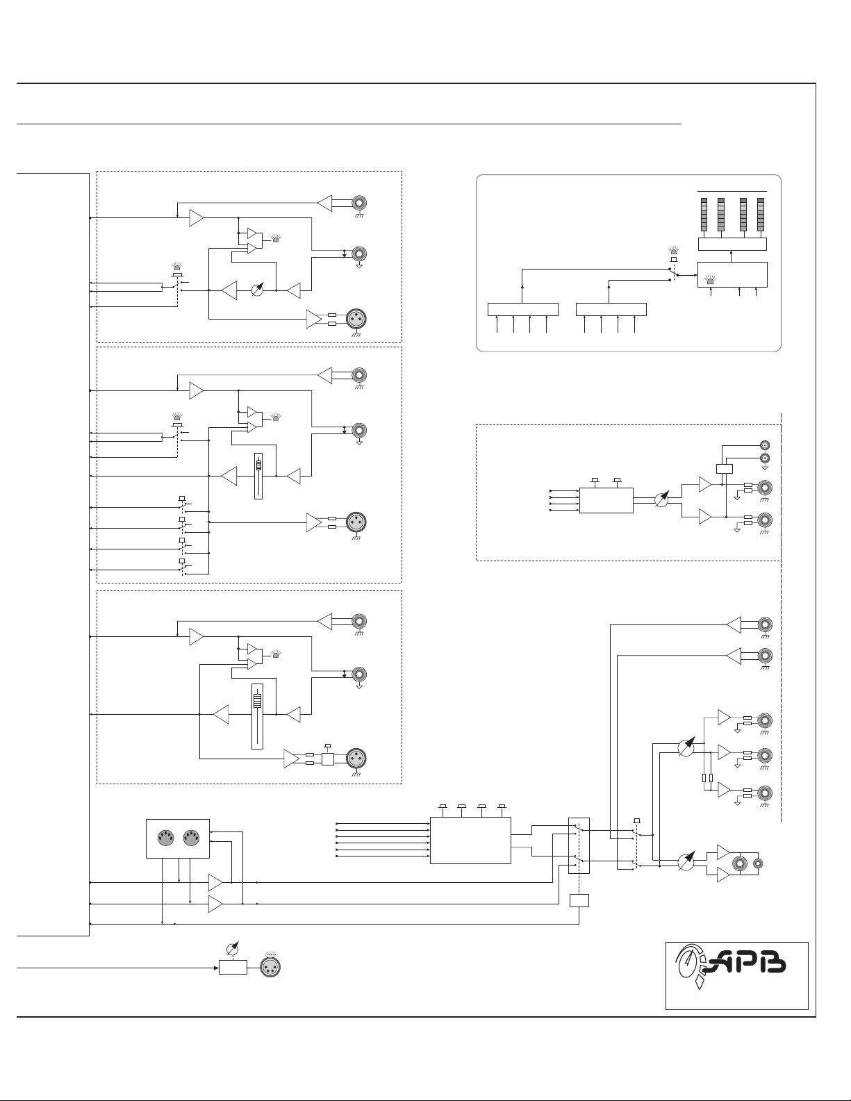
ProRack-FOH Block Diagram
Interconnection
Console
Console
Interconnection
Aux Outputs
1 of 6 shown
Aux Mix Bus
Solo Left
Solo Right
Solo DC
AFL on Aux 5 & 6
is Stereo-linked
Group Outputs
1 of 4 shown
Group Mix Bus
Solo Left
Solo Right
Solo DC
Group Meter Feed
Mono Bus
Center Bus
Left Bus
Right Bus
Aux 1 to 6
AFL
Groups 1 to 4
AFL
Group Bus
Assignment
Grp To
Mono
Grp To
Center
Grp To
Left
Grp To
Right
Aux
Mix Amp
Group
Mix Amp
Fader
Amp
Fader
Amp
Master Metering
9
Bus In
+4dBu
Peak
Sig
10dB
Aux
Level
Peak
Sig
10dB
Group
Fader
Tip
Aux Insert
-2dBu
Ring
Aux Out
+4dBu
Bus In
+4dBu
Tip
Group Insert
-2dBu
Ring
Group Out
+4dBu
Stereo Alternate Out
Mono
Center
Post-fader
Main Outs
Right
Grp-1 Grp-2 Grp-3 Grp-4Mono Center Left Right
Group Out put SignalsMain Output Signals
- Add -
Center Mono
Signal
Left
Summing
L & R Always Active
Stereo
Level
Group
Meters
Alt
9
6
3
0
3
6
12
24
Meter Drivers
Solo Met er Switch-over Logic
Left Right
Solo Aud io
Solo DC
Signals
Signal
-12dB
6
3
0
3
6
12
24
L
R
Left
Stereo
Alt Out
Right
Main Outputs
1 of 4 shown
Main Mix Bus
Main Meter Feed
Solo-L
Mix Amp
Solo-R
Mix Amp
Solo-DC
Mono, Center, Left, Right
Main
Mix Amp
Fader
Amp
Solo Linking
In Out
Low-current LED to Hi-current Halogen.
10dB
100mm
Main
Fader
Single Stereo fader
for Left & Right
Solo Aud io
Signals
Intensity
Trimmer
Any style lamp can be used;
Peak
Sig
Post-fader
Outputs
4-Pin XLR
for 12V Lamps.
Level
Mono
Center
Right
Aux 5
Aux 6
Right
Left
Ext
Monitor In
Bus In
+4dBu
To Mon & HP
Source Select
Tip
Main Insert
-2dBu
Ring
Left
Mic
Main Out
+4dBu
Monitor Source Select
CenterMono
Left
All Signals Summed
Aux
L-R
5-6
Solo
Audio
Switch
DC
Logic
Ext
Mon
Monitor
Level
Headphone
Level
Headphone
Jacks
on Front Panel
Right
Sum
Monitor
Out
DynaSonics
ProRack-H1020
Block Diagram
Page 10
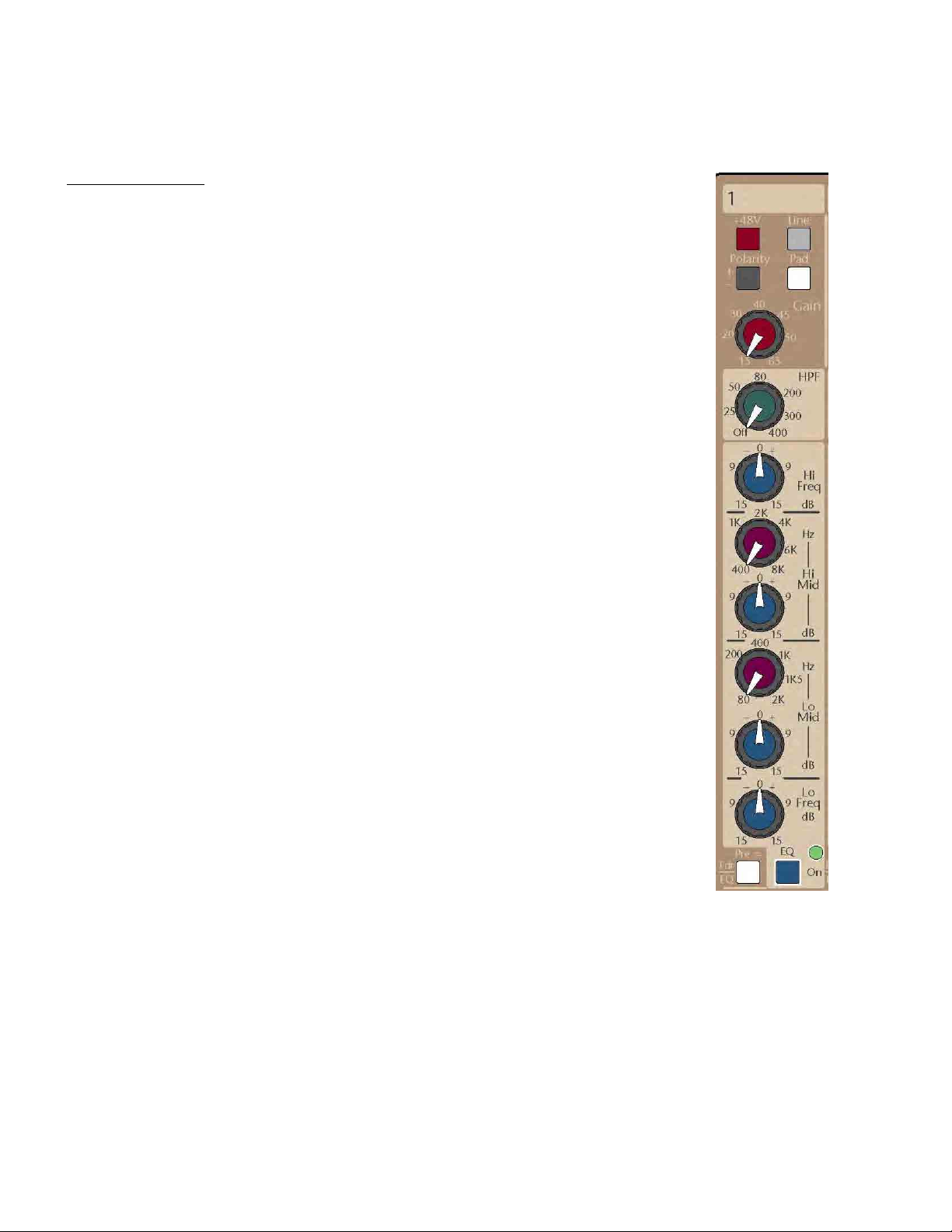
PRORACK HOUSE - MONO INPUT CHANNELS (1-12)
Channel Preamp
48 Volt Phantom Power Switch
When depressed, activates 48-Volt phantom power to the XLR connector. Phantom power is required
for operation of most condenser microphones. See your microphone instructions to see if phantom
power is required or is to be defeated (some –though few-microphones require phantom power NOT
be activated or they may be damaged). Some active Direct Boxes can also use phantom for power.
Mic/Line Switch
Selects between mic input source on XLR connector and line input source on the XLR connector or 1/4”
Line input Jack. When in the UP position, the XLR source is processed as a microphone input signal.
When in the DOWN position, the input is processed as a line level signal from the XLR connector or 1/4”
connector, with the 1/4” connector having priority over the XLR connector. If both connectors are inuse, this switch will select between the XLR (Up) and the TRS (Down)
Polarity Reverse Switch
When depressed, reverses the electrical input polarity of any microphone or line level input signal. Use
of this control may alter the sound quality of an input relative to other channels when multiple
microphones are picking up the same sound. (In the past, many consoles labeled this function as
“Phase” or used the Ø symbol).
Pad Switch
When depressed, inserts a 26dB pad into the microphone input signal path prior to the microphone
preamplifier to prevent overload of excessively high microphone input signal levels. Use this pad
switch when you find that you are operating the gain control in the lower 20% of the control range and
still showing excessive signal levels (yellow and red indications) on the channel meters.
Input Gain Control
This control adjusts the amount of gain at the input stage for the best signal performance within the
console. The goal is to achieve the best signal-to-noise while amplifying input signals to workable
levels, neither too high nor low. The channel’s six-segment meter is used for visualization of proper
channel levels while soloing the channel will give more detailed level information by using the higher
resolution meters in the Master section. Proper level is achieved when there is continuous full green
illumination when input sources are at their highest levels with occasional flashes of the yellow and red
LEDs.
10
Page 11
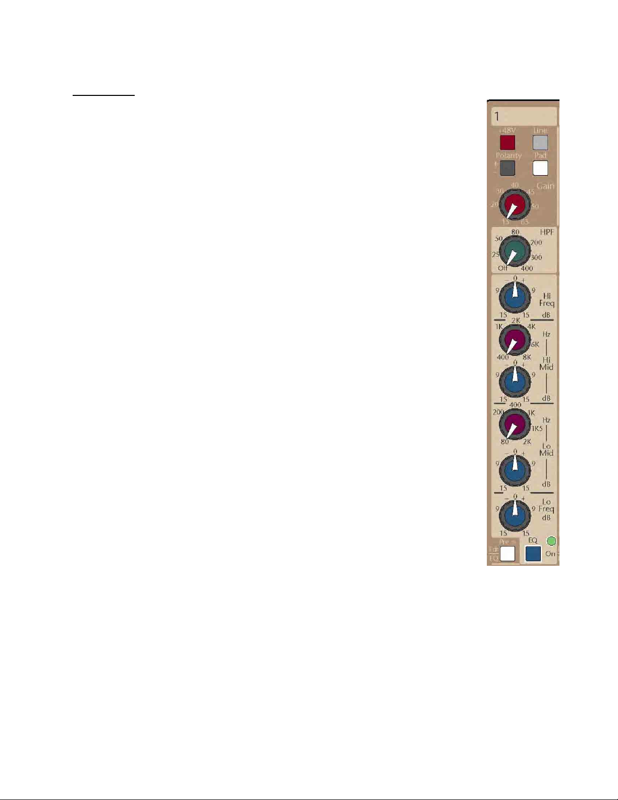
PRORACK HOUSE - MONO INPUT CHANNELS (1-12)
Channel EQ
High Pass Filter Control
Adjusts the high pass filter frequency between 20Hz and 400Hz at a roll off rate of 12dB per octave.
This control is used to remove unwanted signal content below the indicated frequency, such as stage
rumble. This results in a clearer signal that reduces low frequency buildup in an audio system, which
is often perceived as a muddy signal. When this control is turned fully counter-clockwise, the filter
circuitry is removed from the signal path to maintain optimum phase response.
NOTE: The High-Pass filter is NOT controlled by the EQ On switch (See below).
High Frequency Level Control - Shelving
Adjusts the high frequency shelving EQ response between +/-15dB. The center, or "0", position of
this control has a detent to indicate that it is having no effect on the associated channel signal. Boost
or cut of the high frequency level control is used for tonal adjustments. The corner frequency of the
shelving filter is 10kHz.
High-Mid Frequency Control
This frequency control selects the center frequency of the high-mid frequency band EQ between
400Hz and 8 kHz with a bandwidth of approximately one octave.
High-Mid Level Control
Adjusts the high-mid frequency cut/boost between +/-15dB. The center “0” position of this control
has a detent to indicate it is having no effect of this frequency band. The high-mid frequency controls
are used for minor tonal adjustment or repair of a specific band of frequencies.
Low-Mid Frequency Control
This frequency control selects the center frequency of the low-mid frequency band between 80Hz
and 2 kHz with a bandwidth of approximately one octave.
Low-Mid Level Control
Adjusts the low-mid frequency cut/boost between +/-15dB. The center “0” position of this control
has a detent to indicate it is having no effect of this frequency band. The low-mid frequency controls
are used for minor tonal adjustment or repair of a specific band of frequencies.
Low Frequency Level Control - Shelving
Adjusts the low frequency shelving response between +/-15dB. The center “0” position of this control
has a detent to indicate that it is having no effect of the associated channel signal. Boost or cut of the
low frequency level control is usually used for minor tonal adjustments. Corner freq is 60Hz
EQ ON Switch with LED
This switch inserts the 4-band EQ into the channel signal path. EQ activation is displayed by the
illumination of an LED next to the EQ On switch. When not in use, it is suggested that the EQ be kept
in the OFF position for the best phase performance.
NOTE: The EQ On switch only affects the 4-band EQ circuitry. The High-Pass Filter is controlled
ONLY by its own rotary control
11
Page 12
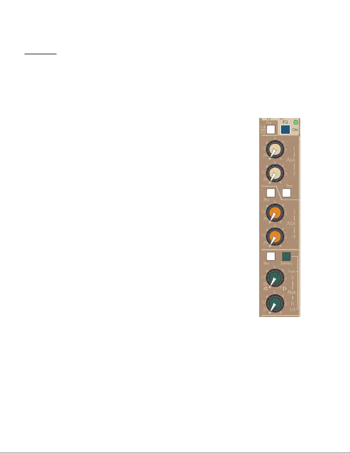
PRORACK HOUSE - MONO INPUT CHANNELS (1-12)
Aux Sends
Aux 1-6 Pre-Fader / Pre-EQ Switch
This switch defines the “Pre” signal source for all Auxes: Up is Pre-Fader (and Post-EQ), Down is Pre-EQ.
Internally, the default Pre-EQ source is set to Post-insert. A qualified technician can change this to a Pre-insert
(Post HPF) on a channel-by-channel basis.
Aux 1-2 Pre Switch
This switch determines the signal source for Aux mixes 1 and 2 between Post-fader (Up) or the above
defined “Pre” signal (Down).
Aux Level Control 1
Adjusts the mix level of the channel into Aux bus 1.
Aux Level Control 2
Adjusts the mix level of the channel into Aux bus 2
Aux 3-4 Pre Switch
This switch determines the signal source for Aux mixes 3 and 4 between Post-fader (Up) or the earlier
defined “Pre” signal (Down).
Aux Level Control 3
Adjusts the mix level of the channel into Aux bus 3.
Aux Level Control 4
Adjusts the mix level of the channel into Aux bus 4
Aux 5-6 Pre Switch
This switch determines the signal source for Aux mixes 5 and 6 between Post-fader (Up) or the earlier
defined “Pre” signal (Down).
Aux 5-6 Stereo Switch
Reconfigures the individual 5 and 6 Aux level controls from two level controls to a level control (6) and
a pan control (5) between bus 5 and 6. This enables a stereo mix to be generated from within this aux
send section for use with stereo headphones, effects, or a discrete stereo mix for recording or broadcast
use.
Aux 5 Level Control
When in normal mono mode, controls the signal level feeding Aux bus 5. When the Aux 5-6 stereo
switch is depressed, this knob now operates as a pan control and adjusts the balance of the signal
being fed to mix buses 5 (CCW) and 6 (CW).
Aux 6 Level Control
When in normal mono mode, controls the signal level feeding Aux bus 6. When the Aux 5-6 stereo
switch is engaged, this knob becomes the Aux 5-6 level control feeding the above pan control.
12
Page 13
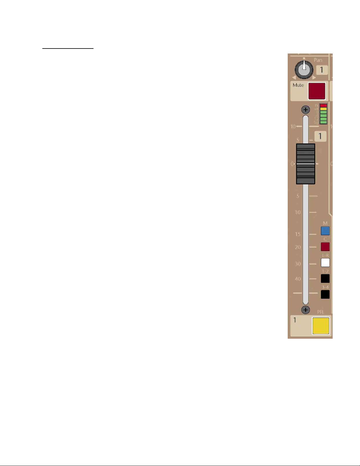
PRORACK HOUSE - MONO INPUT CHANNELS (1-12)
Channel Control
Pan Control
This control blends the post fader signal between any of the assigned bus pairs: L-R, Group1-2 and Group
3-4. When at the center, detented position, both sides are fed equal amounts of signal (each down by
3dB). This pan control has no effect on the Mono or Center mix buses.
Channel Mute Switch (Internally Illuminated)
When pressed, this latching switch will mute the assigned outputs of the channel and all pre and post
auxiliary sends. The Mute does not affect the channel’s PFL feed, channel metering or the Direct Out
(unless it was set for Post-fader). This switch illuminates RED when activated.
Channel Level Meters
6-segment LED meter indicates the pre-fader channel level. The top segment peak indicator will
illuminate red if any of the multiple sample points in the signal chain approaches 3dB of clipping. A yellow
LED illuminates in the caution zone at a +8 reference level. Four green LED segments indicated signal
levels of 0, -6, -12, and Signal Present. The signal present LED first illuminates at approximately -30 and
increases in brightness with level until it is at full intensity. Best operation is achieved when the bottom 3
green LED’s are illuminated with average input signals with only occasional short yellow/red bursts of the
+8 and peak LEDs.
Mono Assignment Switch
Assigns the post-fader channel signal to the Mono mix bus. It is used as a general purpose post fader
output for use as an additional primary console output, aux or matrix send including use for surround or
subwoofer mixes. It may also be used as part of an A-B vocal mix.
Center Assignment Switch
Assigns the post-fader channel signal to the Center mix bus. In mono sound systems, this bus can be used
as the primary (Center) output (leaving the L-R output available for stereo recording). It is usually used in
LCR installations to feed a discrete signal to the center speaker cluster. It may also find use as a general
purpose post fader output for use as an additional aux or matrix send or as part of an A-B vocal mix.
L-R Assignment Switch
Assigns the post-fader channel signal to the Left-Right mix buses through the Pan Control.
1-2 Assignment Switch
Assigns the channel signal to the Group 1 & 2 mix buses through the Pan Control. The Groups can be used
independently using their own insert & XLR output jacks, or used as subgroups and assigned back into
the Main mix buses (See Master Section- Groups).
3-4 Assignment Switch
Assigns the post-fader channel signal to the Group 3 & 4 mix buses through the Pan Control. Operation is
the same as the Group 1 & 2 assignment.
100mm Channel Fader
This high quality fader controls the post-fader channel level.
PFL Switch (Internally Illuminated)
When pressed, this latching switch will route the Pre-fader channel signal to the Solo system (located in
the Master section). This switch illuminates Yellow when activated.
13
Page 14
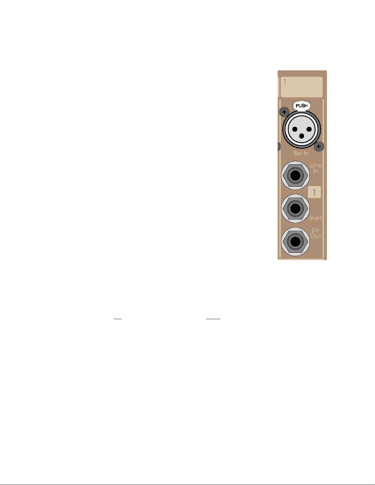
PRORACK - HOUSE Mono Input Channel Connectors (Rear Panel)
XLR Input Connector
This connector accepts microphone or line input signals, as determined by the front panel input
source switch and if the TRS line input connector is occupied. When the front panel input source
switch is in the microphone position (Up), this XLR connector will be used as a microphone input and
will have an input impedance of >3000 ohms. When the input selector source switch is in the LINE
input position (Down) and nothing is plugged into the TRS line input connector, this XLR connector
is used as a balanced line input with an input impedance of >10k ohms. If a connector is plugged
into the TRS line input connector, the XLR connector will always be configured as a microphone
input connector with an input impedance of >3000 ohms. This is a locking connector. To remove an
XLR cable, depress the Tab on the connector before attempting to remove the cable plug from the
console connector.
1/4” TRS Line Input Connector
This connector accepts line input signals and has an input impedance of >10k ohms. When the front
panel source switch is selected to line input, signal is first sourced from this connector. If nothing is
plugged into this connector, the XLR input is normaled through this connector as a line input signal.
The line input may be balanced or unbalanced signal.
1/4” TRS Insert Connector
This connector allows external processing or effects electronics to be inserted into the channel’s
signal path after the variable high pass filter. Tip= Send, Ring= Return, Sleeve= Ground. Examples of
external devices include additional equalization, notch filters, compressors, limiters, vocal doublers
and harmonizers, reverb devices, etc. The insert send has an output impedance of 100 ohms
unbalanced and the insert return has an input impedance of 5k ohms unbalanced.
Operating level is +4dBu.
NOTE: The user should ensure that any device inserted into the channel’s signal path is capable of
maintaining the signal integrity of the console. The device must be able to accept a +22dBu signal
without clipping, and have an output impedance of 100 Ω or less and be capable of driving +22dBu
into a 2k Ω load.
1/4” TRS Direct Output Connector
The connector provides a balanced line level output of the input channel’s signal. The default DO
signal is AFTER the microphone preamplifier but before all other processing. This utility output can
be used to feed a multi-track recording device, effects device, or to feed another mixing or
processing device including distributed monitor mixing systems. Operating level is +4dBu
Direct Output - Internal Options
Internal jumpers may be changed (on a channel-by-channel basis) to Post-insert, Pre-fader or Post-fader.
The Direct Output is always active and
internal-option is implemented.
(Any changes to the Direct Output source should be made by a qualified technician)
not affected by the channel Mute switch unless the Post-fader
14
Page 15
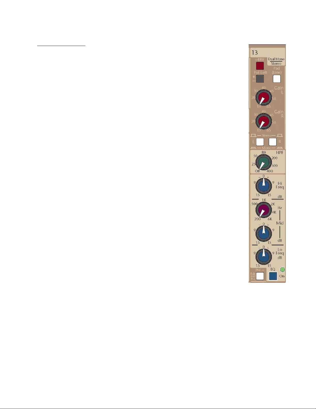
PRORACK HOUSE – DUAL-MONO / STEREO INPUT CHANNELS (13-16)
Channel Preamps
48-Volt Phantom Power Switch
When depressed, activates 48 Volt phantom power to both of the XLR input connectors. Phantom
power is required for operation of most condenser microphones. See your microphone instructions to
see if phantom power is required or is to be defeated (some –though few-microphones require
phantom power NOT be activated or they may be damaged). Some active Direct Boxes can also use
phantom for power.
Pad / Line Input Switch
This dual-purpose switch is used to pad down microphone input levels or enables input channels to
accept line level input signals via the XLR connector. When depressed, it inserts a 26dB pad into the
input signal path prior to the preamplifier to prevent overload of excessively high microphone input
signal levels. Use this pad switch when you find that you are operating the gain control in the lower
20% of the control range and still showing excessive signal levels (yellow and red indications) on the
channel dual meters. Also select this when a line input signal is plugged into the XLR input connectors.
If both connectors are in-use, this switch will select between the XLR (Up) and the TRS (Down)
Polarity Reverse Switch
When depressed, reverses the electrical polarity of -only- the left-side input signal. Use of this control
may alter the sound quality of an input relative to other channels when multiple microphones are
picking up the same sound. (In the past, many consoles labeled this function as “Phase” or used the Ø
symbol).
Left Input Gain Control
This control is used to adjust the input gain of the left-side preamp for optimum performance without
producing audible noise (hiss) at high gain settings. The channel’s LED meters and the solo PFL meters
are used in assisting in setting the control for correct gain levels.
Right Input Gain Control
This control is used to adjust the input gain of the right-side preamp and operates the same as (but
independently of) the left-side gain control.
Dual-Mono / Stereo Source Switches
This pair of switches determines the operating mode of the channel.
If no switches are selected (both Up) the channel acts as a conventional stereo-input channel; left
input signals feed the left-side of the channel, right input signals feed the right-side of the channel.
Stereo separation is maintained through the EQ, fader and (stereo) bus assignments. The Balance
control will adjust the relative levels of the left and right signals being sent to any assigned bus-pairs: LR, Grp 1-2, Grp 3-4.
If both switches are depressed, the left and right inputs are summed to mono after their individual
preamp circuits. The channel now acts as a dual-mono input channel and with separate trim levels for
the two microphone or line inputs (usable when micing similar instruments in close proximity to each
other such as a pair of toms on a drum kit or choir members). Adjustments may be made to each input
for correct balance using the associated input gain control. This summed-signal is then sent equally
through both sides of the channel’s EQ, fader and bus assignment circuitry. The Balance control now
acts as a Pan control and pans this mono signal across any assigned bus-pairs.
If only one switch is depressed, then that single input is selected for use as a mono source and only
that sided preamp is used. This single input is sent equally through the channel’s EQ, fader and bus
assignment circuitry. The Balance control acts as a Pan control and pans this mono signal across any
assigned bus-pairs.
NOTE: If you are going to use the channel as a single-input mono channel, we suggest using the leftside input since you then have a polarity-reverse switch available.
15
Page 16
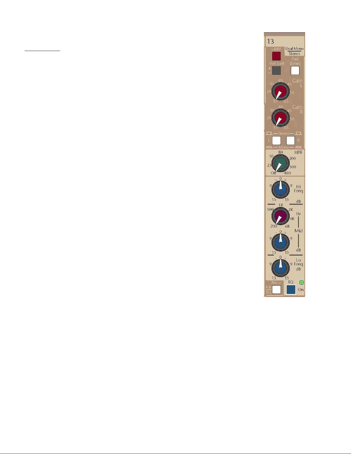
PRORACK HOUSE – DUAL-MONO / STEREO INPUT CHANNELS (13-16)
Channel EQ
High Pass Filter Control
Adjusts the high pass filter frequency between 20Hz and 400Hz at a roll off rate of 12dB per octave
for both sides (L & R) of the channel path. This control is used to remove unwanted signal content
below the indicated frequency, such as stage rumble. This results in a clearer signal that reduces low
frequency buildup in an audio system, which is often perceived as a muddy signal. When this control
is turned fully counter-clockwise, the filter circuitry is removed from the signal path to maintain
optimum phase response.
NOTE: The High-Pass filter is NOT controlled by the EQ On switch (See below).
Hi Frequency Level Control
Adjust the high frequency shelving cut/boost between +/-15dB of both sides (L & R) of the channel. The
center “0” position of this control has a detent to indicate that it is having no effect of the associated
channel signal. Boost or cut of the high frequency level control is usually used for minor tonal
adjustments. Use of this EQ control will affect both the left and right signal paths. Corner freq is 10kHz.
Mid Frequency Control
This frequency control selects the center frequency of the low-mid frequency band between 200Hz and
6 kHz at a bandwidth of approximately one octave.
Mid Level Control
Adjust the low-mid frequency cut/boost between +/-15dB of both sides (L & R) of the channel. The
center “0” position of this control has a detent to indicate it is having no effect of this frequency band.
The mid frequency controls are used for minor tonal adjustment or repair of a specific band of
frequencies.
Low Frequency Level Control
Adjust the low frequency shelving cut/boost between +/-15dB at the reference frequency selected. The
center “0” position of this control has a detent to indicate that it is having no effect of the associated
channel signal. Use of this EQ control will affect both the left and right signal paths. Corner freq is 80Hz
EQ ON Switch with LED
This switch inserts the Left and Right EQ circuitry into the channel signal path. Stereo EQ activation is
displayed by the illumination of the LED. When not in use, it is suggested that the EQ be kept in the OFF
position for best phase performance.
NOTE: The EQ On switch only affects the 3-band EQ circuitry. The High-Pass Filter is controlled
ONLY by its own rotary control
16
Page 17
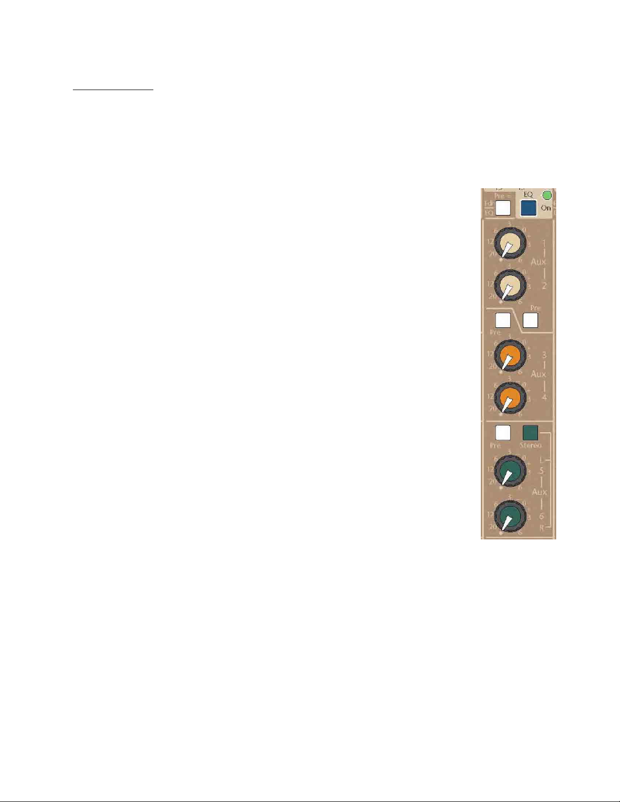
PRORACK HOUSE – DUAL-MONO / STEREO INPUT CHANNELS (13-16)
Channel Auxes
The signals feeding the Aux section are normally mono-mixes of the left & right side signals within
the module. For Auxes 5 & 6, when they are switched to Stereo, the left-side signal feeds the Aux 5
control, the right-side signal feeds the Aux 6 control.
Aux 1-6 Pre-Fader / Pre-EQ Switch
This switch defines the “Pre” signal source for all Auxes; Up is Pre-Fader (Post-EQ), Down is Pre-EQ.
Aux 1-2 Pre Switch
This switch selects the signal source for Aux mixes 1 and 2 between Post-fader (Up) or the above
defined “Pre” signal (Down). The feed to these Auxes is a sum of the left & right channel signals.
Aux Level Control 1
Adjusts the summed mono mix of the channel into Aux bus 1.
Aux Level Control 2
Adjusts the summed mono mix of the channel into Aux bus 2.
Aux 3-4 Pre Switch
This switch selects the signal source for Aux mixes 3 and 4 between Post-fader (Up) or the earlier
defined “Pre” signal (Down). The feed to these Auxes is a sum of the left & right channel signals.
Aux Level Control 3
Adjusts the summed mono mix of the channel into Aux bus 3.
Aux Level Control 4
Adjusts the summed mono mix of the channel into Aux bus 4.
Aux 5-6 Pre Switch
This switch selects the signal source for Aux mixes 5 and 6 between Post-fader (Up) or the earlier
defined “Pre” signal (Down). The feed to these Auxes is a sum of the left & right channel signals.
Aux 5-6 Stereo Switch
Reconfigures the signals feeding the individual Aux 5 and 6 level controls from a summed mono mix
to separate left & right signals.
Aux 5 Level Control
Adjusts the summed mono mix of the channel into Aux bus 5. When the Aux 5-6 stereo switch is
depressed, this control is now reconfigured to only feed the channel’s left-side signal into Aux bus 5.
Aux 6 Level Control
Adjusts the summed mono mix of the channel into Aux bus 6. When the Aux 5-6 stereo switch is
depressed, this control is now reconfigured to only feed the channel’s right-side signal into Aux bus 6.
17
Page 18
PRORACK HOUSE – DUAL-MONO / STEREO INPUT CHANNELS (13-16)
Assignment
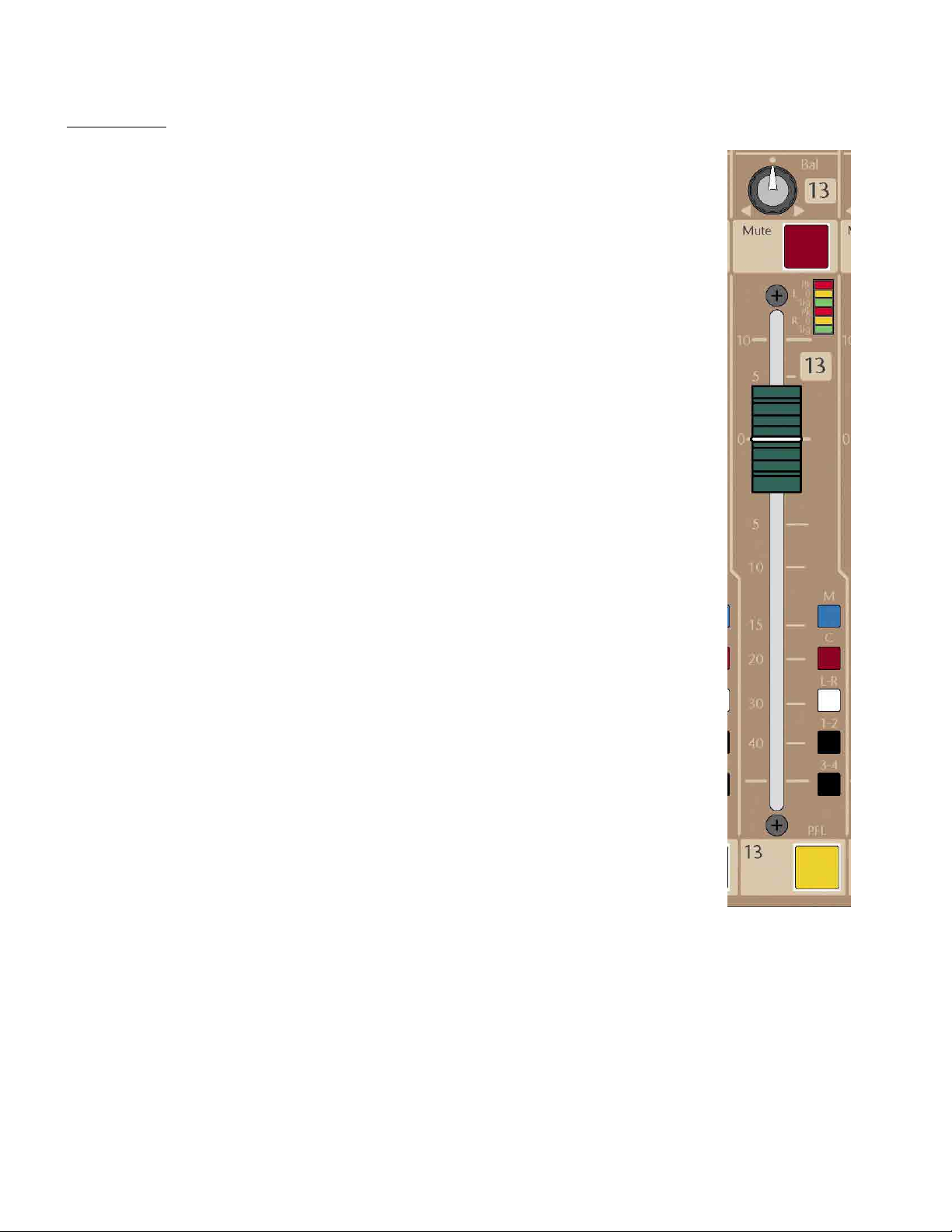
Balance Control
This control blends the post-fader signal between any of the assigned bus-pairs: L-R, Group1-2 and Group
3-4. When at the center, detented position, both sides are fed equal amounts of signal (each down by
3dB). This Balance control has no effect on the Mono or Center mix buses. When the channel mode
switches are both in their Up position (see earlier section), this control acts as a balance control between
the channel’s left and right assigned signals. If any of the mode switches are depressed (mono operation),
this control performs as a pan control between the assigned bus-pairs.
Channel Mute Switch (Internally Illuminated)
When pressed, this latching switch will mute the assigned outputs of the channel and all pre and post
fader auxiliary sends. The Mute does not affect the channel’s PFL feed or channel metering. This switch
illuminates RED when activated.
Channel Level Meters
2 x 3 segment LED meter indicates pre fader channel level. The top segment (1 left, 1 right channel) peak
indicator will illuminate red if any of the multiple sample points in the stereo signal chain approaches 3dB
of clipping. A yellow LED on each channel illuminates in the caution zone at a +8 reference level. The
green signal present LED first illuminates at approximately -30 and increases in brightness with level until
it is at full intensity on each channel. Best operation is achieved when the green LEDs are illuminated with
average input signals with only occasional short yellow/red bursts of the +8 and peak LEDs.
Mono Assignment Switch
Assigns the post-fader summed-channel signal to the Mono mix bus. It is used as a general purpose post
fader output for use as an additional primary console output, aux or matrix send including use for
surround or subwoofer mixes. It may also be used as part of an A-B vocal mix.
Center Assignment Switch
Assigns the post-fader summed-channel signal to the Center mix bus. In mono sound systems, this bus
can be used as the primary (Center) output (leaving the L-R output available for stereo recording). It is
usually used in LCR installations to feed a discrete signal to the center speaker cluster.
L-R Assignment Switch
Assigns the post-fader channel signals to the Left & Right mix buses through the Balance Control. In
Stereo or Dual Mono sound systems, this is the most likely used primary output assignment on the
console. The Left & Right outputs are also typically used for music reproduction when Center or Mono mix
buses are used for the Center-fill or sub output of the Console.
1-2 Assignment Switch
Assigns the post-fader channel signals to the Group 1 & 2 mix buses through the Balance Control. The
Groups can be used independently using their own insert & XLR jacks, or used as subgroups and assigned
back into the Main mix buses (See Master Section- Groups).
3-4 Assignment Switch
Assigns the post-fader channel signals to the Group 3 & 4 mix buses through the Balance Control.
Operation is the same as the Group 1 & 2 assignment.
100mm Channel Fader
This high quality stereo fader controls the post-fader channel levels.
PFL Switch (Internally Illuminated)
This switch will internally illuminate yellow when activated. It will route Pre-Fader dual-mono/stereo
signal to the master section for display on the Left/Right solo meters and into the monitor/headphone
systems.
Discrete Sub Woofer Feed Using Mono Assignment Bus
The MONO bus may be used as a fixed level discrete feed to a subwoofer system. The Left-Right, Center, and Mono outputs are
controlled from three individual master faders that when adjusted equally maintains balance between all outputs including the
MONO sub output when master signal levels are changed.
18
Page 19
PRORACK HOUSE – DUAL-MONO / STEREO INPUT CHANNELS
Rear Panel
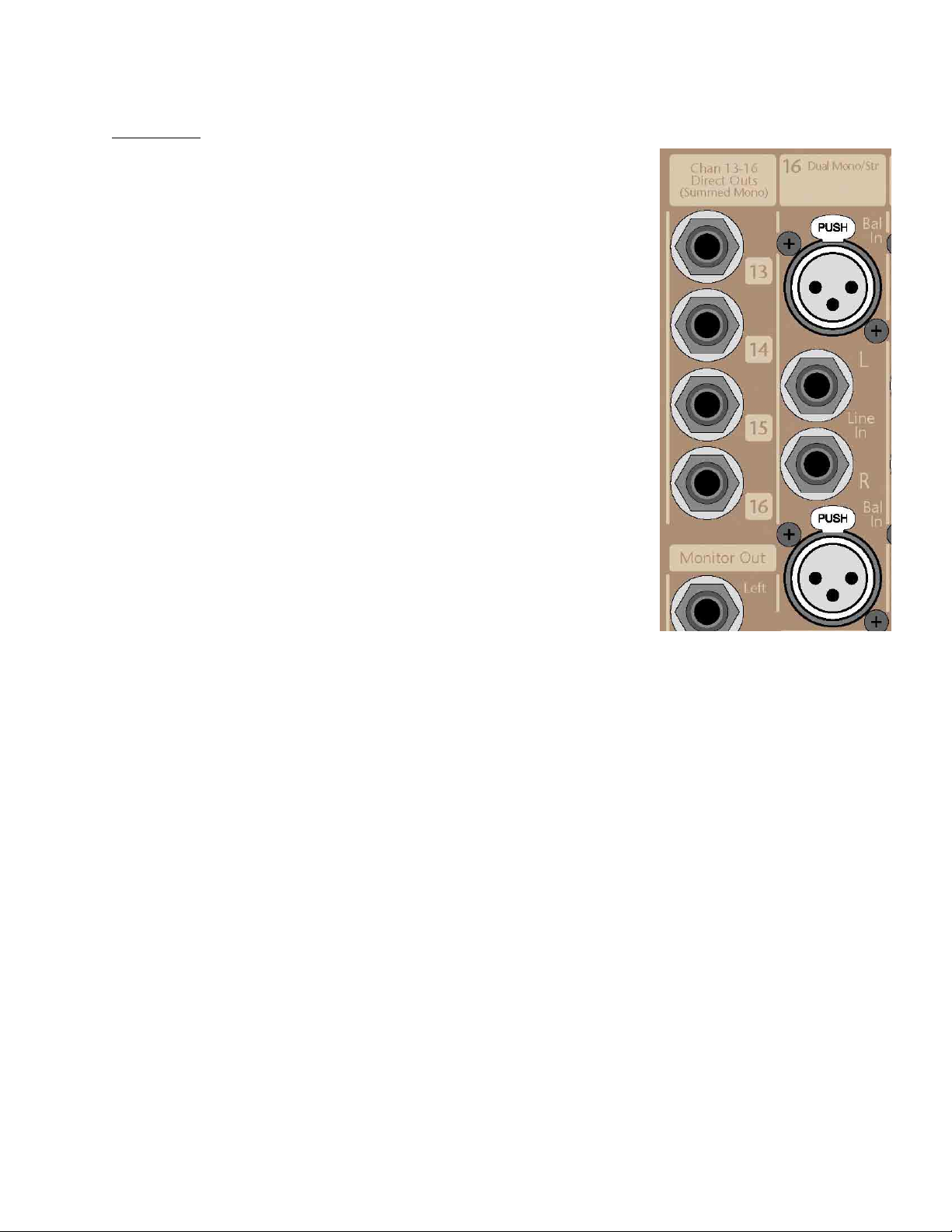
XLR Input Connector (Separate for left and right inputs).
This connector accepts microphone or line input signals, as determined by the front
panel combination Mic/Line – Pad switch.
This is a locking connector. To remove an XLR cable, depress the Tab on the connector
before attempting to remove the cable plug from the console connector.
1/4” TRS Line Input Connector (Separate for Left and Right inputs)
This connector accepts line input signals and has an input impedance of >10k ohms.
The line input may be balanced or unbalanced signal.
1/4” TRS Direct Output Connector (Summed-Mono Output)
The connector provides a line level output of the input channel’s Post-HPF/Pre-EQ
signal. This output can be used to feed a multi-track recording device, effects device,
or to feed another mixing or processing device including distributed monitor mixing
systems. Operating level is +4dBu.
19
Page 20
PRORACK HOUSE – MASTER SECTION
GROUP CONTROL SECTION
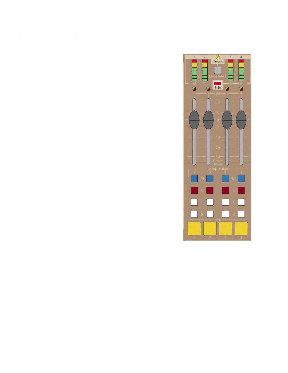
Group Metering
When the Group Meter Select switch located above the group faders is depressed,
the meters located directly above these four group faders will display the post-fader
output levels as they appear on the rear panel XLR connectors. When selected, the
associated “Groups” LED will illuminate (yellow) to indicate that the meters are set to
display group output levels.
Signal Level LED
This bi-color Red/Green LED monitors the signal level on the associated Group mix
bus. Varying intensity Green indicates proper bus levels while Red indicates the bus is
at or near overload; this should be an indication to the operator that the channel
input fader levels should be decreased until the red peak indicators are no longer
activated. The red Peak LED monitors the mix bus output, Insert-return AND the postfader signal levels.
Group Level Control Fader
This fader will adjust the output level appearing on the XLR balanced group output
connector and the levels being sent to any of the assigned Master buses.
Mono, Center, Left, Right Assignment Switches
Allows the associated Group post-fader signal (post insert) to be assigned to any of
the primary output buses of the console. This is useful when an operator wishes to
form an analog subgroup for the purposes of inserting a common signal processing
device or to have common control a “group” of assign selected input channel signals.
For subgroup control of a stereo group signal being fed to the primary outputs, an
adjoining group pair would be used with the LEFT assignment switch selected on the
odd number channel and the RIGHT assignment switch selected on the even number
of channel.
Group AFL Switch (Internally Illuminated)
When selected, this switch will route post fader (post insert point) signal to the
consoles PFL/AFL Solo system for display on the consoles master meters and to the
mixers monitor/headphone system.
20
Page 21

GROUP OUTPUT CONNECTORS – REAR PANEL
Balanced 1/4” TRS Group Bus-Inputs
The 10k ohm balanced inputs are provided to bring an external line level signal into the Group mix amp (prior to the fader
level control). This allows any group fader to be used as an additional line level input into the mixer. It may also be used as
part of the system to link multiple mixers together by bring the group output signal of the slave mixer (output level set to
unity) into these group TRS connectors. Any signal brought into these group inputs will be mixed with any other input
signals assigned to this group mix bus.
Group 1/4” TRS Insert Connector
This connector allows external processing or effects electronics to be inserted into the Group’s signal path after the mix amp.
Tip= Send, Ring= Return, Sleeve= Ground. Examples of external devices include additional equalization, notch filters,
compressors, limiters, vocal doublers and harmonizers, reverb devices, etc. The insert send has an output impedance of 100
ohms unbalanced and the insert return has an input impedance of 5k ohms unbalanced.
Operating level is -2dBu.
NOTE: The user should ensure that any device inserted into the Group signal path is capable of maintaining the signal
integrity of the console. The device must be able to accept a +22dBu signal without clipping, and have an output impedance
of 100 Ω or less and be capable of driving +22dBu into a 2k Ω load.
XLR Balanced Group Output
This is an 100 ohm electronically balanced line level output on an XLR connector designed to drive a 600 ohm load or greater.
Operating level is +4dBu
21
Page 22
PRORACK HOUSE – MASTER SECTION
AUXILARY CONTROL SECTION
Auxiliary Output Level Control (1 thru 6)
This control will adjust the auxiliary output level appearing on the associated XLR
balanced output connector.
Dual-Color Bus Level LED Monitoring
This bi-color Red/Green LED monitors the signal level on the associated auxiliary mix
bus. Varying intensity Green indicates proper bus levels while red indicates the bus is
at or near overload, indicating that an auxiliary level control reduction should be
made on the associate auxiliary mix channel. The red Peak LED monitors the mix bus
output, Insert-return AND the post-level control signal levels.
Auxiliary AFL (Solo) Switch (Internally illuminated)
When selected, this switch will route post level (post insert point) auxiliary signal to
the consoles PFL/AFL Solo system for display on the consoles master meters and to
the mixers monitor/headphone system. If AFL switches 5-6 are simultaneously
depressed, contents will be monitored as a stereo Left-Right signal into the meters
and into the Monitor/Headphone system of the mixer.
22
Page 23
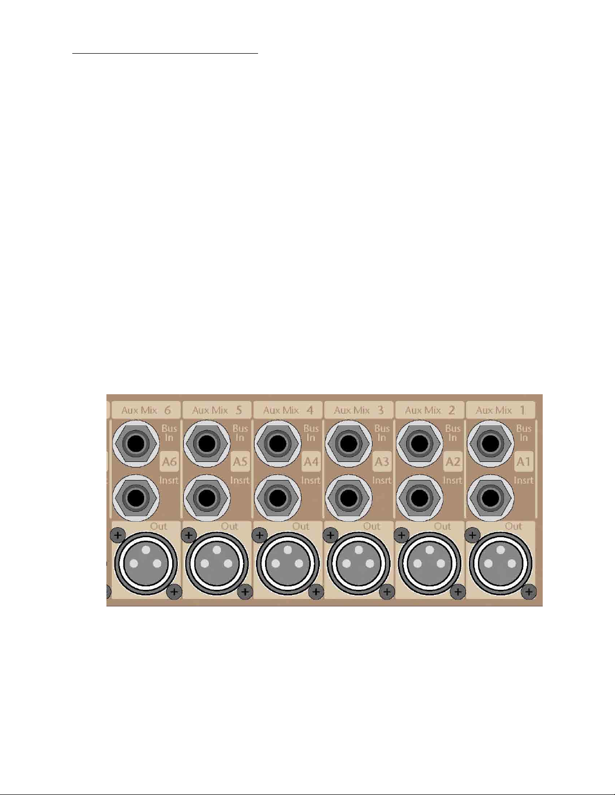
AUX OUTPUT CONNECTORS – REAR PANEL
Balanced 1/4” TRS Auxiliary Bus-Inputs
The 10k ohm balanced inputs are provided to bring an external line level signal into an auxiliary bus prior to its level control. It may
be used as part of the system to link multiple mixers together by bring the auxiliary output signal of the slave mixer (output level set
to unity) into these auxiliary input TRS connectors. Any signal brought into these auxiliary inputs will be mixed with any other input
signals fed to this auxiliary mix bus.
Aux 1/4” TRS Insert Connector
This connector allows external processing or effects electronics to be inserted into the Aux signal path after the mix amp.
Tip= Send, Ring= Return, Sleeve= Ground. Examples of external devices include additional equalization, notch filters,
compressors, limiters, vocal doublers and harmonizers, reverb devices, etc. The insert send has an output impedance of 100
ohms unbalanced and the insert return has an input impedance of 5k ohms unbalanced.
Operating level is +4dBu.
NOTE: The user should ensure that any device inserted into the Aux signal path is capable of maintaining the signal integrity of the
console. The device must be able to accept a +22dBu signal without clipping, and have an output impedance of 100 Ω or less and be
capable of driving +22dBu into a 2k Ω load.
XLR Balanced Auxiliary Output
This is an 50 ohm electronically balanced line level output on an XLR connector designed to drive a 600 ohm load or greater.
Operating level is +4dBu
23
Page 24
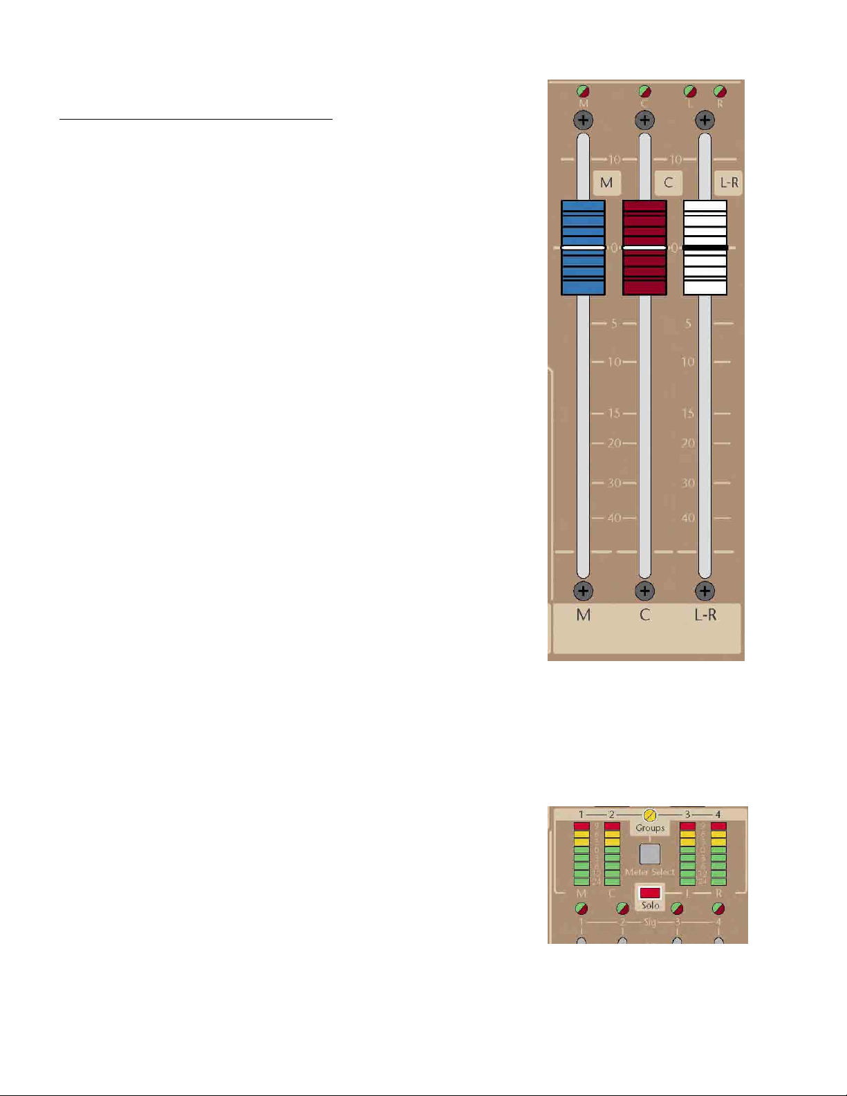
PRORACK HOUSE – MASTER SECTION
MASTER OUTPUTS (Left-Right, Center, Mono)
Peak/Signal Present Bus Monitor LED’s
4 individual dual-color LEDs monitor the Mono, Center, Left and Right mix bus levels.
In normal operation, varying intensity of the green LED represents acceptable bus
signal levels. Should any of these levels approach clipping, the associated LED will
illuminate red. This should be an indication to the operator that the channel input
fader levels should be decreased until the red peak indicators are no longer activated.
(Overall output levels can be adjusted by raising the master fader position to offset
any decrease in level caused by lowering the input channel faders). . The red Peak
LED monitors the mix bus output, Insert-return AND the post-fader signal levels.
Mono, Center and Left/Right Level Control Faders
These faders adjust the output level appearing on the associated XLR balanced
group output connectors. Each control has a range of from cut-off to +10dB of gain
above unity. A single fader is used to control the Left/Right output level maintaining
an absolute balance for these outputs as master level changes are made. Though
two master faders are labeled as Center and Mono, these should be considered as
two separate mono outputs that are usable for whatever application that required a
mono signal derived directly from the selected input channels. These include uses
to feed a center speaker cluster (use of the Center fader suggested), a sub-woofer
feed (use of the Mono fader suggested), or uses as additional post fader auxiliary
sends or matrix outputs.
Master Output Metering (Left - Right - Center - Mono Outputs)
The post-fader levels of the Mono, Center, Left and Right outputs are displayed on
the 4 master meters. Any PFL/AFL (Solo) switch will cause the 2 right-most meters to
display the solo’d signal in place of the master output signals. These same meters
can be manually switched to display the 4 Group output signal levels.
24
Page 25
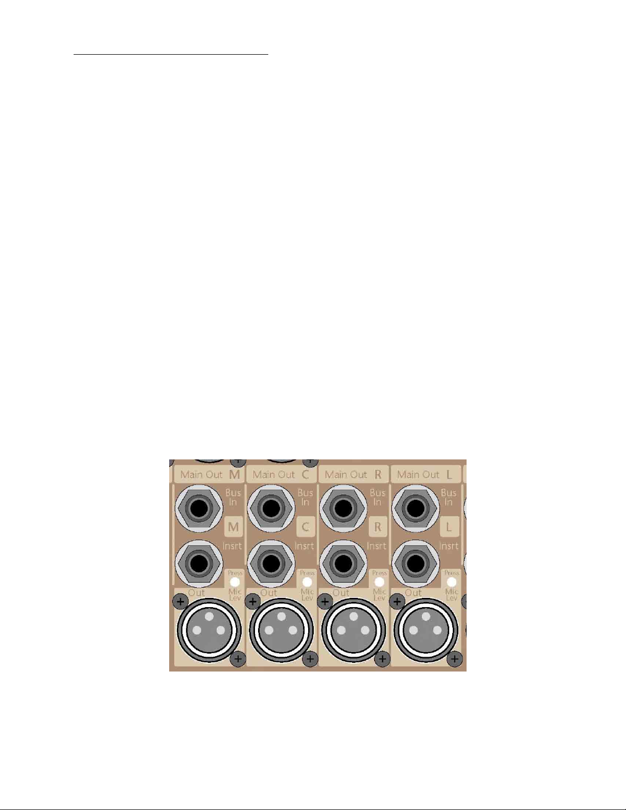
MAIN OUTPUT CONNECTORS – REAR PANEL
Balanced 1/4” TRS Bus Inputs
Left, Right, Center and Mono 10k ohm balanced inputs are provided to bring an external line level signal into the Main mix
buses prior to their level controls. These may be used as part of the system to link multiple mixers together by bring the
master output signal of the slave mixer (output level set to unity) into these master input TRS connectors. Any signal brought
into these inputs will be mixed with the associated Left, Right, Center and Mono signal on the master mixer.
Main Bus 1/4” TRS Insert Connector
This connector allows external processing or effects electronics to be inserted into the Main signal path after the mix amp.
Tip= Send, Ring= Return, Sleeve= Ground. Examples of external devices include additional equalization, notch filters,
compressors, limiters, etc. The insert send has an output impedance of 100 ohms unbalanced and the insert return has an
input impedance of 5k ohms unbalanced. Operating level is -2dBu.
NOTE: The user should ensure that any device inserted into the Main signal path is capable of maintaining the signal integrity
of the console. The device must be able to accept a +22dBu signal without clipping, and have an output impedance of 100 Ω
or less and be capable of driving +22dBu into a 2k Ω load.
Line/Microphone Level Output Switches
The output level of ProRack XLR connectors is normally at +4dBu. This is designed to drive most amplifiers to their maximum
levels or signal processing equipment to their optimum levels. In some situations you may need to plug the output of this
mixer into the microphone input of another mixer or sound system. By depressing the Mic/Line switch next to the associated
XLR output connector, output signal levels will be reduced approximately 30dB to normal microphone levels. This signal now
can be applied to the microphone input channel of another mixing device. (Warning – Make sure that phantom power is
turned OFF on the microphone input of the mixer into which ProRack is being connected or damage may result).
Mono, Center, Left and Right XLR Balanced Outputs
These outputs provide a +4dBu balanced line level output (100 ohm symmetrically-balanced) signal for each of the consoles primary
outputs.
When Mic Level is selected, output impedance is 200 ohms and operating level is –25dBu.
25
Page 26
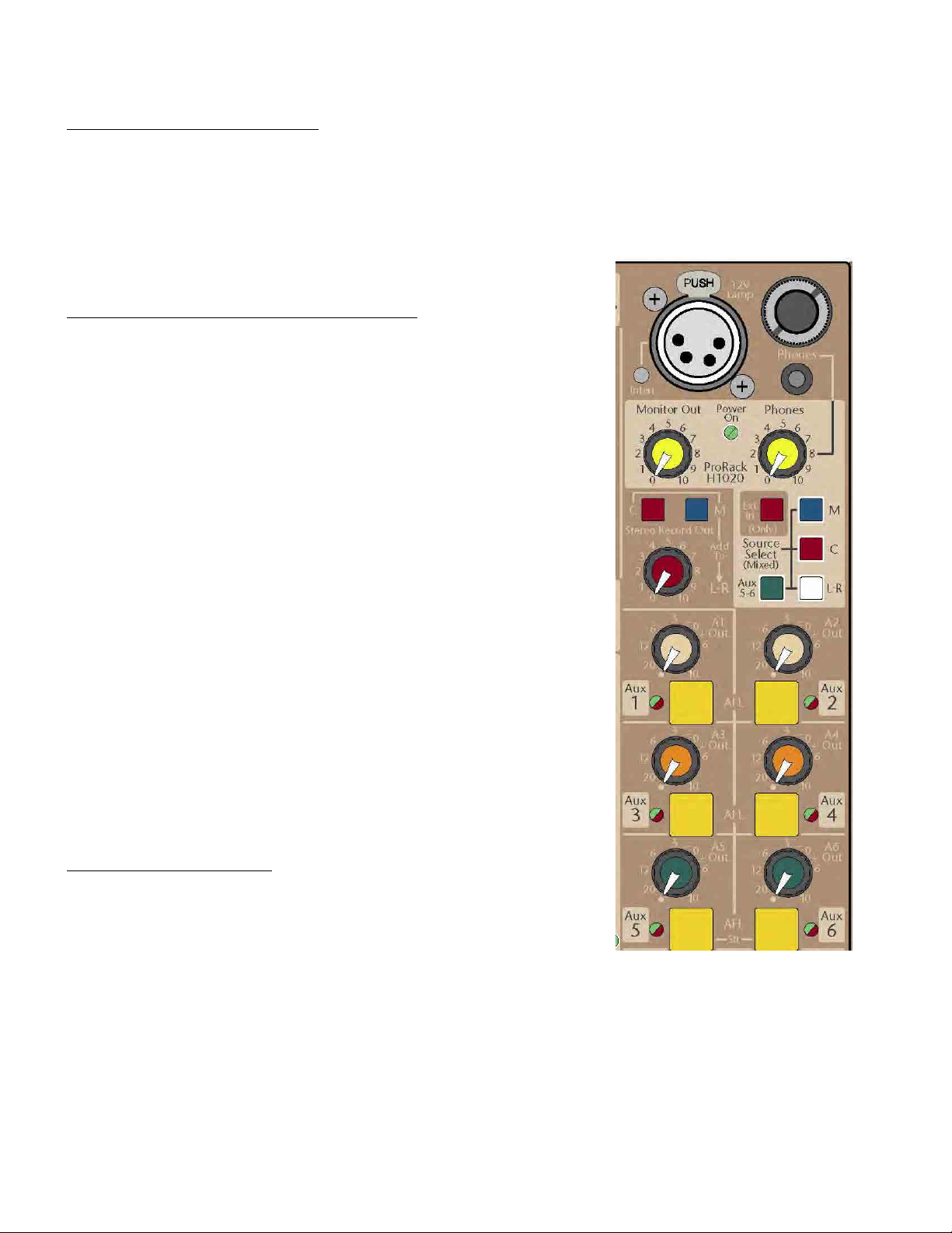
PRORACK HOUSE – MASTER SECTION
HEADPHONE AND MONITOR SYSTEM
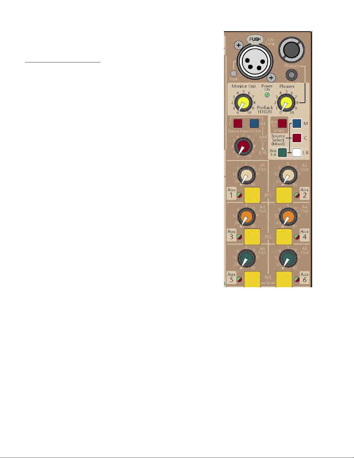
Headphone Level Control
This control adjusts the level being fed to the headphone system.
1/4” And 1/8” Headphone Connectors
A 1/4” and a 1/8” set of headphone connectors are located on the front panel of the console.
Monitor (Speaker) Level Control
This control adjusts the stereo level being fed to the Monitor TRS output connectors of the
mixer.
Monitor/Headphone Source Selection Switches
These 5 switches determine the default audio source for the Monitor system (Monitor
and Headphone outputs). The first 4 switches select from the internal buses: Mono,
Center, L-R and Aux 5-6. These 4 sources are equally mixed together when their
corresponding switch is depressed; any mono sources are sent equally to the L & R sides
of the monitor circuitry. When Solo is active (PFL or AFL), the Solo audio signal interrupts
this default source and only the Solo audio is fed to the monitor circuitry (*See below)
Mono (M) Headphone/Monitor Source Switch
When selected, this switch will route a post master fader Mono signal equally to the left
and right stereo headphones and monitor level controls as a “phantom center” image.
Center (C) Headphone/Monitor Source Switch
When this switch is selected, it will route a post master fader Center signal equally to the
left and right stereo headphones and monitor level controls as a “phantom center”
image.
Left-Right (L-R) Headphone/Monitor Source Switch
When selected, this switch will route a post master fader left-right signal to the left and
right stereo headphone and monitor level controls.
Aux 5-6 Headphone/Monitor Source Switch
When this switch is depressed, it will route a post level control Aux 5 (left) and Aux 6
(right) stereo signal to the monitor system. This allows for monitoring of this set of
auxiliary outputs as a default signal without using the Solo system. This is useful when
Aux 5-6 are being used to generate a separate broadcast output.
External Input Headphone/Monitor Source Switch
When this switch is selected, it will route an external input to the headphone and
monitor system from the rear panel left and right external input connectors. (On older
consoles, this input was usually referred to as tape inputs).
* When this switch is depressed, it will override ALL other audio sources that may
be selected for monitoring, including any Solo signal (PFL or AFL). If nothing is
being fed to the External Line Inputs (on rear), then NOTHING will be heard in
Monitor and Headphone outputs. Check this switch first if the headphones seem to
be not working.
ADDITIONAL STEREO OUTPUT
Stereo Alternate Level Control
This control adjusts an additional stereo output that can be used to feed an external
recording device or additional physical location (such as a cry room). In addition to the Left
& Right buses, the mixer’s Center or Mono buses may also be mixed in with the Left & Right
signals if desired (see below).
Add C(enter) To L-R
Adds the signal from the Center bus to the Left-Right Stereo Alt Outputs. This enables an LCR
console output to be sent as a Left-Right signal to a recording device while in the FOH system
the signals are still separated into a Left-Right music system and a Center vocal only system.
Add M(ono) To L-R
Adds the signal from the Mono bus to the Left-Right Stereo Alt Outputs. This enables the Mono
bus output to be added to the left-right mix and used as an overall Left-Right signal to recording
device.
NOTE: All of the signals feeding the Stereo Alt Out section are after the main faders (Post-fader)
26
Page 27
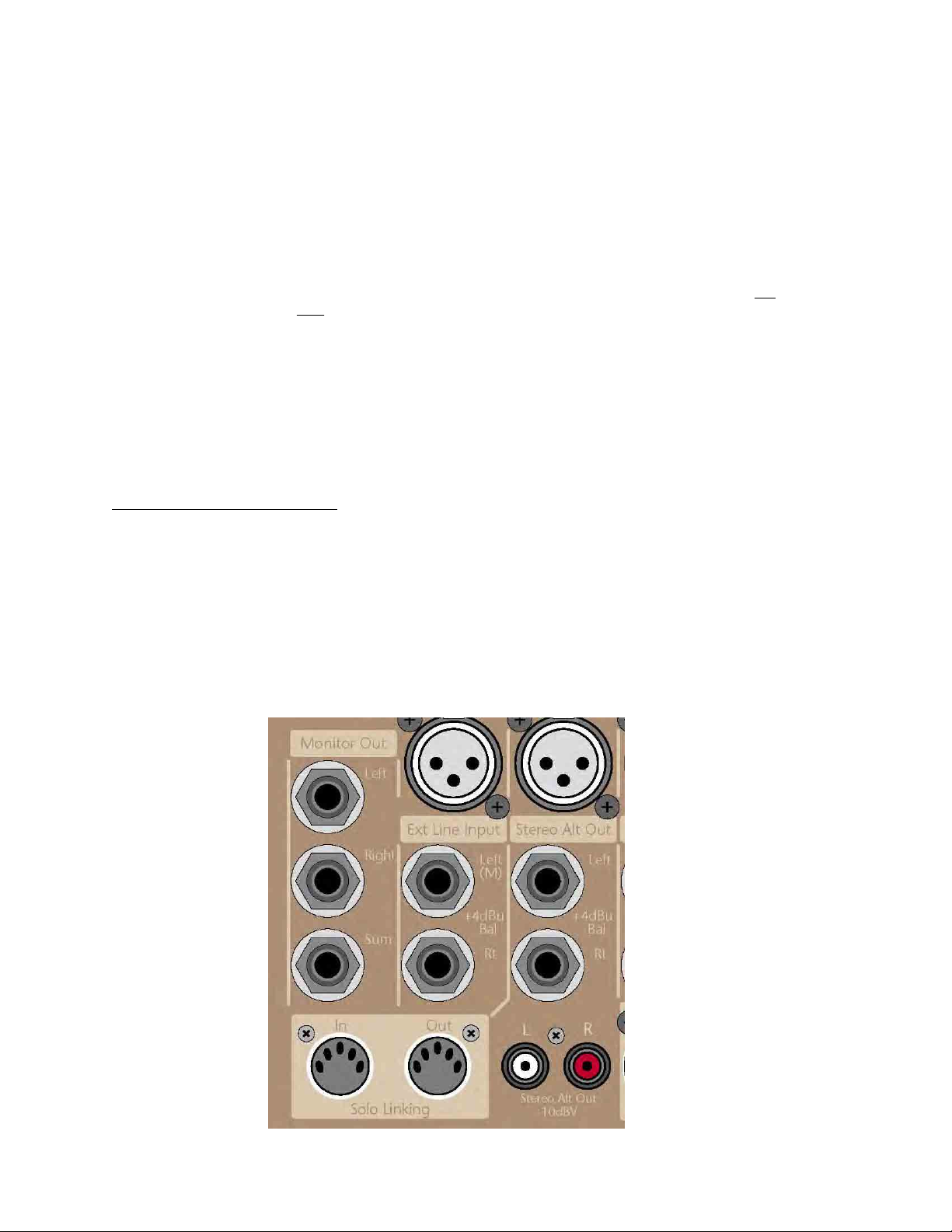
PRORACK HOUSE – MASTER SECTION REAR PANEL
Rear Panel Monitor Output Connectors
Impedance Balanced 1/4” output connectors are provided for Left and Right monitor speaker outputs. An additional 1/4” Impedance
Balanced output connector is provided which is a sum of the Left, and Right signals. This connector may be used as a summed mono
output to feed a sub-woofer system or to drive a mono wedge monitor system when the console is used as a monitor console.
External Input Connectors
Balanced 1/4” input connectors are provided for monitor of an external signal such as monitoring a signal directly off of a radio
broadcast; separate left & right connectors are provided. If a mono source needs to be monitored, plugging into
input jack will feed the signal to
both the left & the right sides of the monitor system.
1/4” Left and Right Stereo Alternate (Record) Output Connectors
Impedance-balanced left and right 1/4” TRS connectors are provided at a +4dBu operating level for the Stereo Alternate Output.
(Output Impedance = 100 ohms Impedance Balanced).
RCA Stereo Alernate (Record) Outputs
RCA connectors are also provided for low level outputs (-10dBV) of the stereo alternate output to better match the input
requirements of consumer grade recording devices.
SOLO (PFL/AFL) LINKING SYSTEM
Two 5-pin DIN connectors are provided that allow the Solo systems of multiple ProRack mixers to be linked together. Thus, a single
set of headphones can be used to monitor the solo functions of multiple mixers. This Solo-linking can also be used with a larger APB
Spectra console if it is fitted with a Solo Linking option.
Use a 5-pin circular DIN cable to link the OUT connector of the Slave console to the IN connector of the Master console. Any Solo
activity on the Slave console will still show up on that console but will now also activate the Solo function on the Master console
where the Slave’s solo audio can be heard, mixed in with any Master Solo activity.
The DIN cable should be wired pin-to-pin with an overall shield tied to the connector shells on each end.
Contact APB about where to obtain a Solo-Linking cable.
just the Left
27
Page 28
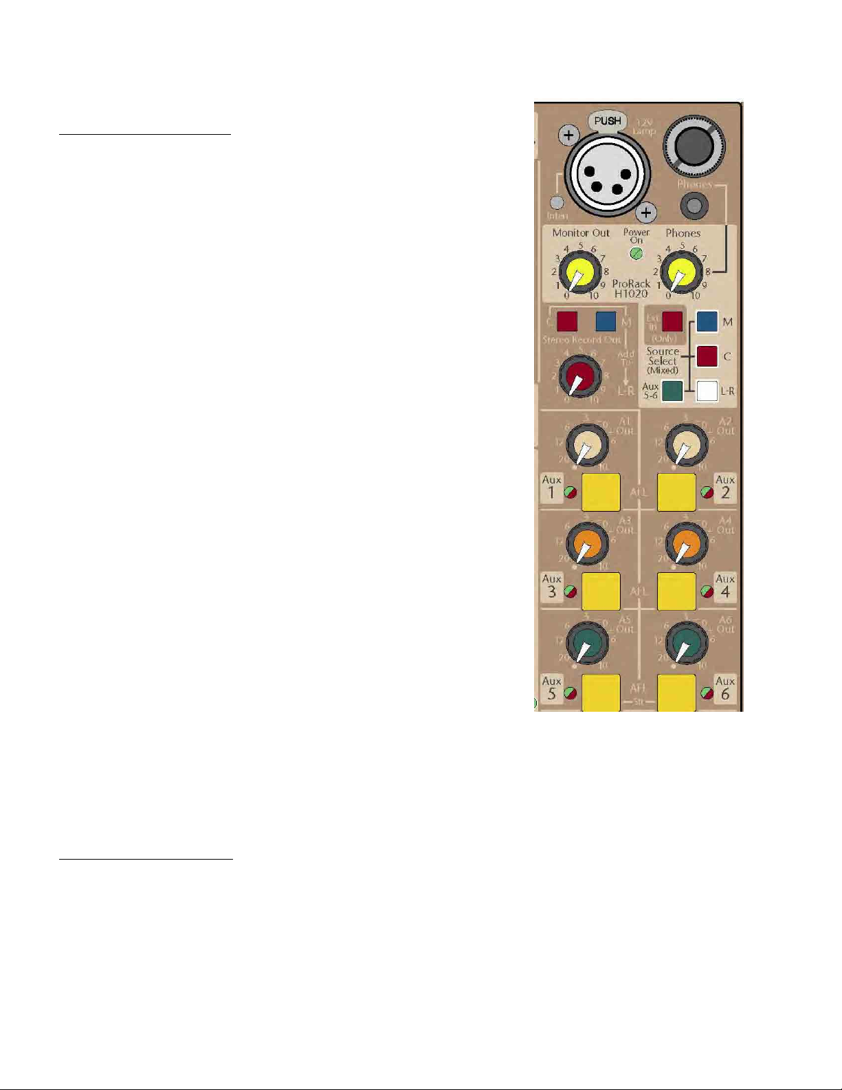
PRORACK HOUSE – ADDITIONAL FEATURES
LAMP AND DIMMER SYSTEM
4-Pin XLR Lamp Connector
A four-pin XLR connector can be used with a Littlite® or other similar gooseneck
lamp. Compatible with Hi-intensity (Halogen), regular incandescent or LED lamps. A
straight, 12-inch length gooseneck works best for this console. A locking connector
is provided for this lamp which must be depressed and held while removing the
plug in lamp.
Positive voltage on Pin-4, 0V on Pin-3, No Connection to Pins 1 & 2.
An internal resettable fuse protects against shorts on this connector.
Maximum allowed current draw is 350mA @ 12V.
Lamp Intensity Control
A recessed trimmer control is provided adjust the brightness of the plug-in lamp.
This may be adjusted with a small flat-blade or jeweler’s screwdriver. Maximum
brightness is achieved by turning this control to its full clockwise position (12V);
minimum brightness at full counter-clockwise (< 2V).
ROTATING CONNECTOR POD
The rear connector chassis may be rotated between three different locking positions. When used freestanding on a desktop, the fully
opened 90-degree position is recommended. When mounted in an upright rack, the 180-degree position may be selected. In an
angled rack, a mid position may be the best choice. The connector panel is locked into position using the two provided #10-32
screws on each side of the panel. Remove these screws before trying to rotate panel or damage (maybe to you) may result. It is
suggested to reinstall these screws once the panel position is selected.
If these screws are lost, replace with #10-32 x 1/4” Flat-head Stainless Steel screws- maximum length allowed is 3/8”.
Do not transport the mixer with the rear panel unsecured. See the following pages for additional mounting information.
28
Page 29
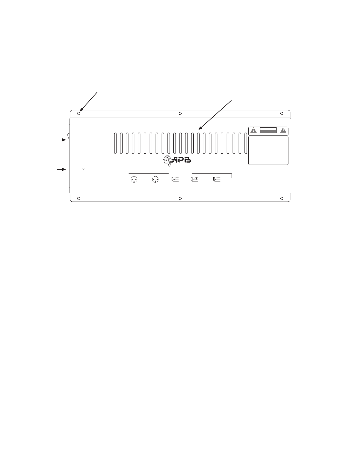
ProRack Power Supply
Model PRPS-60
6 screws are located along this lower flange to
mount the power supply assembly to the rear of
the ProRack chassis. #6-32 x 1/4” Hex-drive Panhead
Ventilation slots- keep these clear of any obstructions
when using the ProRack.
Air is drawn in through these slots and exhausted
through slots in the ProRack chassis
CAUTION
RISK OF ELECTRIC SHOCK
DO NOT OPEN
RISQUE DE CHOC ÉLECTRIQUE—NE PAS OUVRIR
AC
Power Sw
IEC AC
Inlet
Off
Power
On
AC IN
100-240V
50/ 60 Hz
70W
1= Chassis
12
2= Out +
3
3= Out –
XLR Outputs
12
3
1= Chassis
2= In +
3= In –
DynaSonics
ProRack™ Series
Designed and Built in the USA
Audio Connections
T= In +
R= In –
S= Chassis
T= Send
R= Return
S= Audio Gnd
Insert WiringXLR Inputs
T= Out +
R= Out Rtn
S= Chassis
Dir OutputsLine/Bus Inputs
AVIS :
WARNING: TO PREVENT FIRE OR SHOCK HAZARD, DO
NOT EXPOSE THIS APPLIANCE TO RAIN OR MOISTURE. THE
APPARATUS MUST NOT BE EXPOSED TO DRIPPING OR
SPLASHING AND NO OBJECTS FILLED WITH LIQUIDS, SUCH
AS VASES, SHOULD BE PLACED ON THE APPARATUS.
AVERTISSEMENT:
AFIN DE PRÉVENIR TOUT RISQUE DE FEU OU DE CHOC
ÉLECTRIQUE, ÉVITEZ D’EXPOSER CET APPAREIL À LA PLUIE
OU À L’HUMIDITÉ. NE PAS PLACER DE RÉCIPIENT DE LIQUIDE
À PROXIMITÉ DE L’APPAREIL, AFIN D’ÉVITER DES
ÉCLABOUSSURES OU RENVERSEMENTS SUR CELUI-CI.
MOUNT IN RACK ONLY
INSTALLER SUR SUPPORT DE MONTAGE SEULEMENT
NO USER SERVICEABLE PARTS INSIDE.
REFER SERVICING TO QUALIFIED SERVICE PERSONNEL
ProRack Power Supply
Model PRPS-60
APB-DynaSonics
20 West End Road
Totowa, New Jersey 07512
www.apb-dynasonics.com
The power supply for the ProRack is designed to be easily field-replaced:
6 screws secure it to the rear panel of the ProRack; a captive wire-lead with locking connector is used to
mate with the circuits within the Mixer. A small internal fan circulates air through the supply into the Mixer.
All internal power supply assemblies are medically-rated and agency approved (UL/CSA/VDE/CE).
There are no user-serviceable parts inside; heed all printed warnings.
Input Voltage: 100 to 240 VAC 50/60Hz
Input Power: <72W
AC Mains Connector: IEC 15A Receptical
ProRack is supplied with mating IEC cordset with either an Edison-plug (USA/Canada) or Euro-plug (Export)
DC Output Voltages & Currents (as used by the ProRack):
+17.6V @ 1.3A
-17.6V @ 1.3A
+15V @ 1A
+48V @ 0.2A
DC Output Connector: 7-Way Molex 0.156” pitch
Page 30
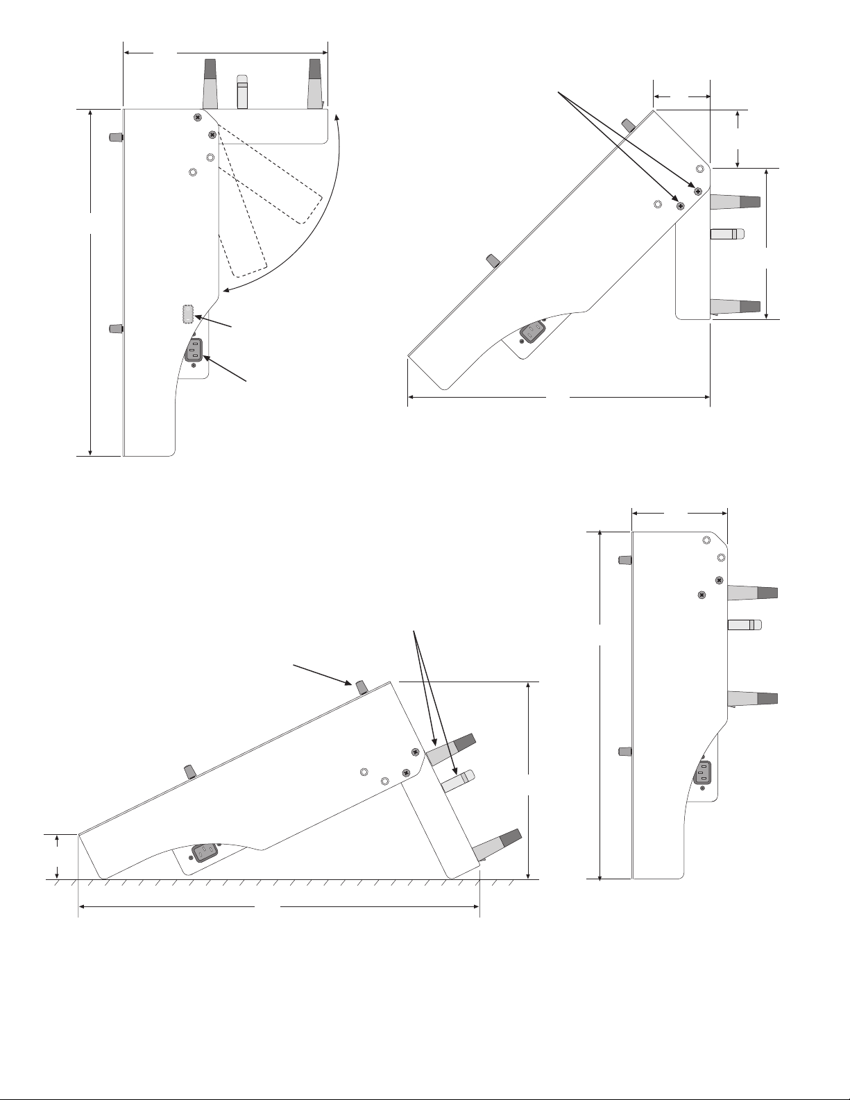
10.5
(267)
Note Different Position Of Locking Screws
For Each Orientation Of The Rear Chassis:
#10-32 X 1/4” UC Flat-head Phillips
2 Per Side To Secure The Rear Chassis
3
(77)
17.5
(445)
The Rear Chassis can freely
rotate from a fully-open
position (90°) to fully-closed
(180°). 3 locking positions are
provided using 2 screws per
side to secure the chassis.
AC power switch located
on this side of power supply
(hidden by mounting ear)
IEC AC Inlet located
on this (right) side of
power supply
MOUNTED IN A VERTICAL RACK
SIDE VIEW (UNFOLDED)
15
(381)
MOUNTED IN A SLANT-RACK
SIDE VIEW (HALF-FOLDED)
4.85
(124)
3
(77)
11.5
(292)
Knob height= 0.75 (19)
2
(51)
20.25
(515)
USED AS A DESK TOP MIXER
SIDE VIEW
Dimensions shown for the different orientations
Given in inches and (mm)
-to the closest 1/4” or mm -
Weight= 34 lbs (15.5kg) for all orientations
Shipping Weight (boxed)= 40 lbs (18kg)
Typical XLR and TRS plugs
(Shown for reference only)
10
(254)
17.5
(445)
MOUNTED IN A VERTICAL RACK
SIDE VIEW (FOLDED)
ProRack Mounting Options
Page 31
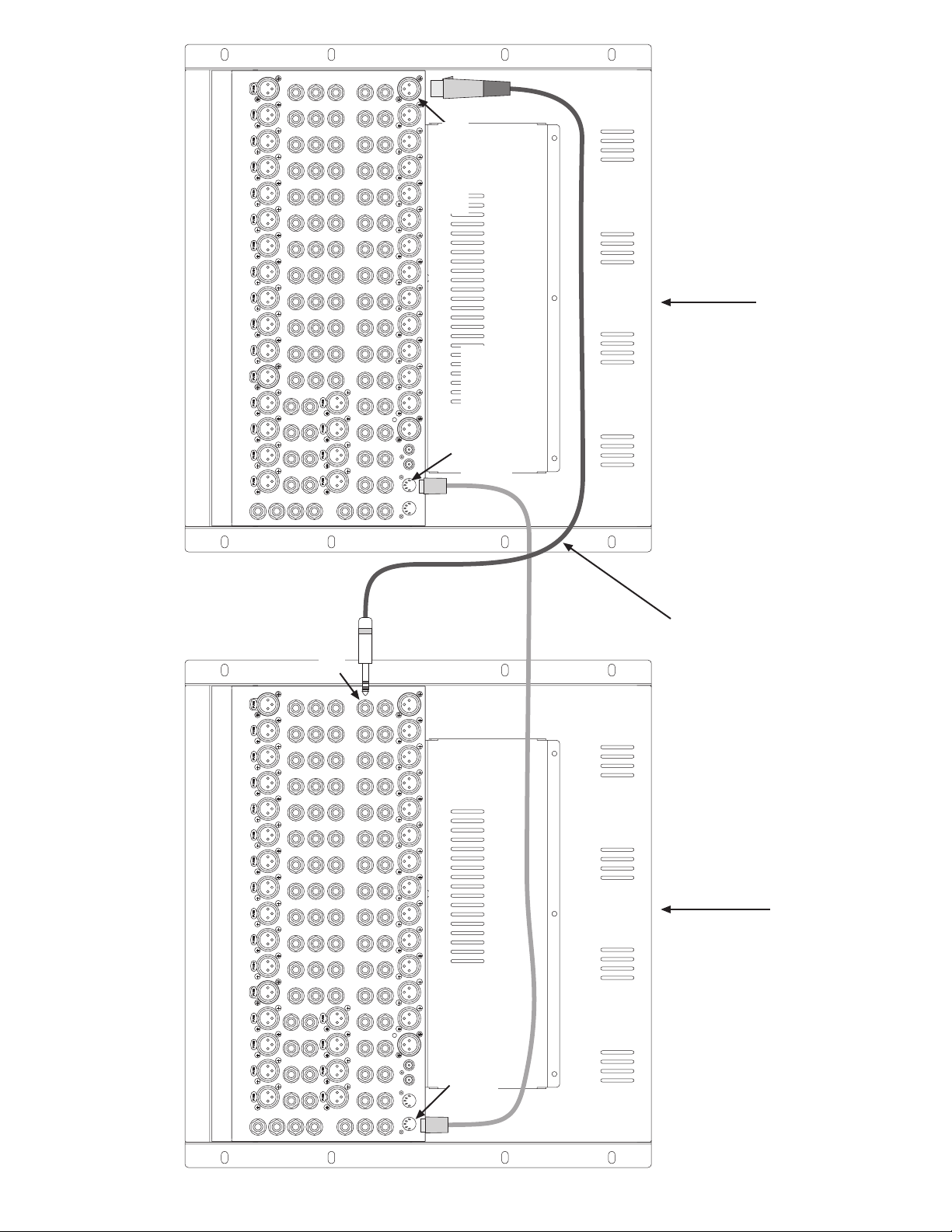
Balanced Out
M-XLR Pin-2 Hot
POWER SUPPLYPOWER SUPPLY
Wired Pin-to-Pin
Solo Linking Out
5-Pin Circular DIN
w/overall shield to Shell
- Slave Console -
at both ends of the cable.
To ensure correct mixing levels into the Master console,
Solo System is linked between Consoles with a single DIN cable:
Each end fitted with 5-Pin circular DIN connector wired pin-to-pin
all bus output controls on the Slave console should be set to “0” (unity).
with 5 conductor (overall) shielded cable. Shield tied to connector shell
TRS Tip= Hot
Balanced Bus-In
as Master and Slave
Interconnecting two ProRack Mixers
Solo Linking In
Wired Pin-to-Pin
5-Pin Circular DIN
w/overall shield to Shell
6 Auxes, 4 Groups, 4 Main (M, C, L, R)
that will be shared across the 2 consoles.
16-way XLR to 1/4” TRS Audio Snake can be used
14 connections needed to tie all like-buses together
Repeat this connection for each of the Bal-Out / Bus-In pairs
- Master Console -
Solo also monitored from this Mixer
into the Master Console buses at unity gain.
Audio signals from all buses in the Slave Console are mixed
Page 32

Page 33

Page 34
n
A
A
e
k
8
0
6
2
g
P
A
e
a
G
K
1
1
0
0
APB-DynaSonics
ProRack-FOH
Track Sheet
DynaSonics
ProRack
H1020
A1
A2
A3
A4
A5
A6
1
+48V
Polarity Pad
+
–
40
30
20
65
15
80
50
20
Off
400
0
+
–
15915
2K
1K
0
+
–
15915
400
200
0
+
–
15915
0
+
–
15915
Pre =
F
EQ
3
–
6
12
20
•
3
–
6
12
20
•
Pre
3
–
6
12
20
•
3
–
6
12
20
•
Pre
3
–
6
12
20
•
3
–
6
12
20
•
45
4K
8K400
1K
2K80
EQ
0
6
0
6
0
6
0
6
Stereo
0
6
0
6
Pan
50
200
300
9
6K
9
1K5
9
9
+
3
+
3
Pre
+
3
+
3
+
3
+
3
Line
Gain
HPF
Freq
Mid
Mid
Freq
Aux
Aux
Pan
Aux
Hi
dB
Hz
Hi
dB
Hz
Lo
dB
Lo
dB
On
1
2
3
4
5
6
Lvl
1
2
+48V
Polarity Pad
+
–
30
20
15
50
20
Off
–
15915
1K
–
15915
200
–
15915
–
15915
Pre
Fdr
EQ
6
12
20
•
6
12
20
•
Pre
6
12
20
•
6
12
20
•
Pre
6
12
20
•
6
12
20
•
Mute
3
Line
+48V
Polarity Pad
+
–
40
Gain
30
45
20
50
65
80
0
2K
0
400
0
0
=
3
3
3
3
3
3
15
HPF HPF HPF HPF HPF HPF HPF HPF
50
200
20
300
Off
400
+
–
9
Hi
Freq
15915
dB
4K
1K
Hz
6K
8K400
Hi
+
–
Mid
9
dB
15915
200
1K
Hz
1K5
2K80
Lo
+
–
Mid
9
dB
15915
+
–
Lo
Freq
9
dB
15915
EQ
Pre
Fdr
On
EQ
–
0
6
+
12
1
3
20
6
•
Aux
–
0
6
+
12
2
3
20
6
•
Pre
Pre
–
0
6
+
12
3
3
20
6
•
Aux
–
0
6
+
12
4
3
20
6
•
Stereo
Pre
–
0
6
Pan
+
12
5
3
20
6
•
Aux
–
0
6
+
12
6
3
20
Lvl
6
•
Pan
2
MuteMute
45678910
Line
40
Gain
45
50
65
80
200
300
400
0
+
9
Hi
Freq
dB
2K
4K
Hz
6K
8K400
Hi
0
+
Mid
9
dB
400
1K
Hz
1K5
2K80
Lo
0
+
Mid
9
dB
0
+
Lo
Freq
9
dB
EQ
=
On
3
–
0
+
1
3
6
Aux
3
–
0
+
2
3
6
Pre
3
–
0
+
3
3
6
Aux
3
–
0
+
4
3
6
Stereo
3
–
0
Pan
+
5
3
6
Aux
3
–
0
+
6
3
Lvl
6
Pan
3
+48V
Polarity Pad
+
–
40
30
20
15
80
50
20
Off
0
–
15915
2K
1K
0
–
15915
400
200
0
–
15915
0
–
15915
=
Pre
Fdr
EQ
3
6
12
20
•
3
6
12
20
•
Pre
3
6
12
20
•
3
6
12
20
•
Pre
3
6
12
20
•
3
6
12
20
•
Mute
65
400
+
8K400
+
2K80
+
+
–
6
–
6
–
6
–
6
Stereo
–
6
–
6
Line
Gain
45
50
200
300
9
Hi
Freq
dB
4K
Hz
6K
Hi
Mid
9
dB
1K
Hz
1K5
Lo
Mid
9
dB
Lo
Freq
9
dB
EQ
On
0
+
1
3
Aux
0
+
2
3
Pre
0
+
3
3
Aux
0
+
4
3
0
Pan
+
5
3
Aux
0
+
6
3
Lvl
Pan
4
+48V
Polarity Pad
+
–
40
30
20
15
80
50
20
Off
0
–
15915
2K
1K
0
–
15915
400
200
0
–
15915
0
–
15915
=
Pre
Fdr
EQ
3
6
12
20
•
3
6
12
20
•
Pre
3
6
12
20
•
3
6
12
20
•
Pre
3
6
12
20
•
3
6
12
20
•
Mute
45
65
400
+
4K
8K400
+
1K
2K80
+
+
–
0
6
–
0
6
–
0
6
–
0
6
Stereo
–
0
6
–
0
6
EQ
Pan
200
300
Pre
Line
50
9
6K
9
1K5
9
9
+
3
Aux
+
3
+
3
Aux
+
3
+
3
+
3
Gain
Freq
Mid
Mid
Freq
Pan
Aux
Hi
dB
Hz
Hi
dB
Hz
Lo
dB
Lo
dB
On
1
2
3
4
5
6
Lvl
5
+48V
Polarity Pad
+
–
40
30
20
15
80
50
20
Off
0
–
15915
2K
1K
0
–
15915
400
200
0
–
15915
0
–
15915
=
Pre
Fdr
EQ
3
6
12
20
•
3
6
12
20
•
Pre
3
6
12
20
•
3
6
12
20
•
Pre
3
6
12
20
•
3
6
12
20
•
Mute
65
400
+
8K400
+
2K80
+
+
–
6
–
6
–
6
–
6
Stereo
–
6
–
6
Line
Gain
45
50
200
300
9
Hi
Freq
dB
4K
Hz
6K
Hi
Mid
9
dB
1K
Hz
1K5
Lo
Mid
9
dB
Lo
Freq
9
dB
EQ
On
0
+
1
3
Aux
0
+
2
3
Pre
0
+
3
3
Aux
0
+
4
3
0
Pan
+
5
3
Aux
0
+
6
3
Lvl
Pan
6
+48V
Polarity Pad
+
–
40
30
20
65
15
80
50
20
Off
400
0
+
–
15915
2K
1K
0
+
–
15915
400
200
0
+
–
15915
0
+
–
15915
=
Pre
Fdr
EQ
3
–
6
12
20
•
3
–
6
12
20
•
Pre
3
–
6
12
20
•
3
–
6
12
20
•
Pre
3
–
6
12
20
•
3
–
6
12
20
•
Mute
45
4K
8K400
1K
2K80
0
6
0
6
0
6
0
6
Stereo
0
6
0
6
Pan
EQ
Line
50
200
300
9
6K
9
1K5
9
9
+
3
+
3
Pre
+
3
+
3
+
3
+
3
Gain
Aux
Aux
Aux
Freq
Mid
Mid
Freq
Pan
Hi
dB
Hz
Hi
dB
Hz
Lo
dB
Lo
dB
5
6
Lvl
7
Polarity Pad
+
–
30
20
50
20
1K
200
Fdr
On
EQ
12
1
20
12
2
20
Pre
12
3
20
12
4
20
Pre
12
20
12
20
Mute
+48V
15
Off
–
15915
–
15915
–
15915
–
15915
Pre
6
•
6
•
6
•
6
•
6
•
6
•
Line
40
Gain
45
50
65
80
200
300
400
0
+
9
Hi
Freq
dB
2K
4K
Hz
6K
8K400
Hi
0
+
Mid
9
dB
400
1K
Hz
1K5
2K80
Lo
0
+
Mid
9
dB
0
+
Lo
Freq
9
dB
EQ
=
On
3
–
0
+
1
3
6
Aux
3
–
0
+
2
3
6
Pre
3
–
0
+
3
3
6
Aux
3
–
0
+
4
3
6
Stereo
3
–
0
Pan
+
5
3
6
Aux
3
–
0
+
6
3
Lvl
6
Pan
8
+48V
Polarity Pad
+
–
40
30
20
15
80
50
20
Off
0
–
15915
2K
1K
0
–
15915
400
200
0
–
15915
0
–
15915
=
Pre
Fdr
EQ
3
6
12
20
•
3
6
12
20
•
Pre
3
6
12
20
•
3
6
12
20
•
Pre
3
6
12
20
•
3
6
12
20
•
Mute
65
400
+
8K400
+
2K80
+
+
–
6
–
6
–
6
–
6
Stereo
–
6
–
6
Line
Gain
45
50
200
300
9
Hi
Freq
dB
4K
Hz
6K
Hi
Mid
9
dB
1K
Hz
1K5
Lo
Mid
9
dB
Lo
Freq
9
dB
EQ
On
0
+
1
3
Aux
0
+
2
3
Pre
0
+
3
3
Aux
0
+
4
3
0
Pan
+
5
3
Aux
0
+
6
3
Lvl
Pan
9
20
20
200
Fdr
EQ
12
12
12
12
12
12
+48V
Polarity P
+
–
40
30
15
80
50
Off
0
–
15915
2K
1K
0
–
15915
400
0
–
15915
0
–
15915
Pre =
3
6
20
•
3
6
20
•
Pre
3
6
20
•
3
6
20
•
Pre
3
6
20
•
3
6
20
•
Li
45
50
65
20
30
400
+
9
4K
6
8K400
+
9
1K
1K
2K80
+
9
+
9
EQ
–
0
+
3
6
–
0
+
3
6
Pr
–
0
+
3
6
–
0
+
3
6
Ster
–
0
+
3
6
–
0
+
3
6
Pa
Mute
Artist
Song
Engineer Date
Pk
+8
0
-6
12
Sig
10
1
5
0
5
10
15
20
L-R
30
1-2
40
3-4
PFL PFL PFL PFL PFL PFL PFL PFL PFL
Pk
+8
0
-6
12
Sig
10
23
5
0
5
10
M
15
C
20
L-R
30
1-2
40
3-4
Pk
+8
0
-6
12
Sig
10
5
0
5
10
M
15
C
20
L-R
30
1-2
40
3-4
Pk
+8
0
-6
12
Sig
10
4
5
0
5
10
M
C
M
15
20
L-R
30
1-2
40
3-4
Pk
+8
0
-6
12
Sig
10
5
5
0
5
10
15
C
20
L-R
30
1-2
40
3-4
Pk
+8
0
-6
12
Sig
10
6
5
0
5
10
M
15
C
20
L-R
30
1-2
40
3-4
Pk
+8
0
-6
12
Sig
10
7
5
0
5
10
M
15
C
20
L-R
30
1-2
40
3-4
Pk
+8
0
-6
12
Sig
10
8
5
0
5
10
M
C
M
15
20
L-R
30
1-2
40
3-4
Pk
+8
0
-6
12
Sig
10
9
5
0
5
10
P
+
-
1
Si
10
5
0
5
10
M
15
C
20
30
40
15
C
20
L-R
30
1-2
40
3-4
12345678910
Page 35
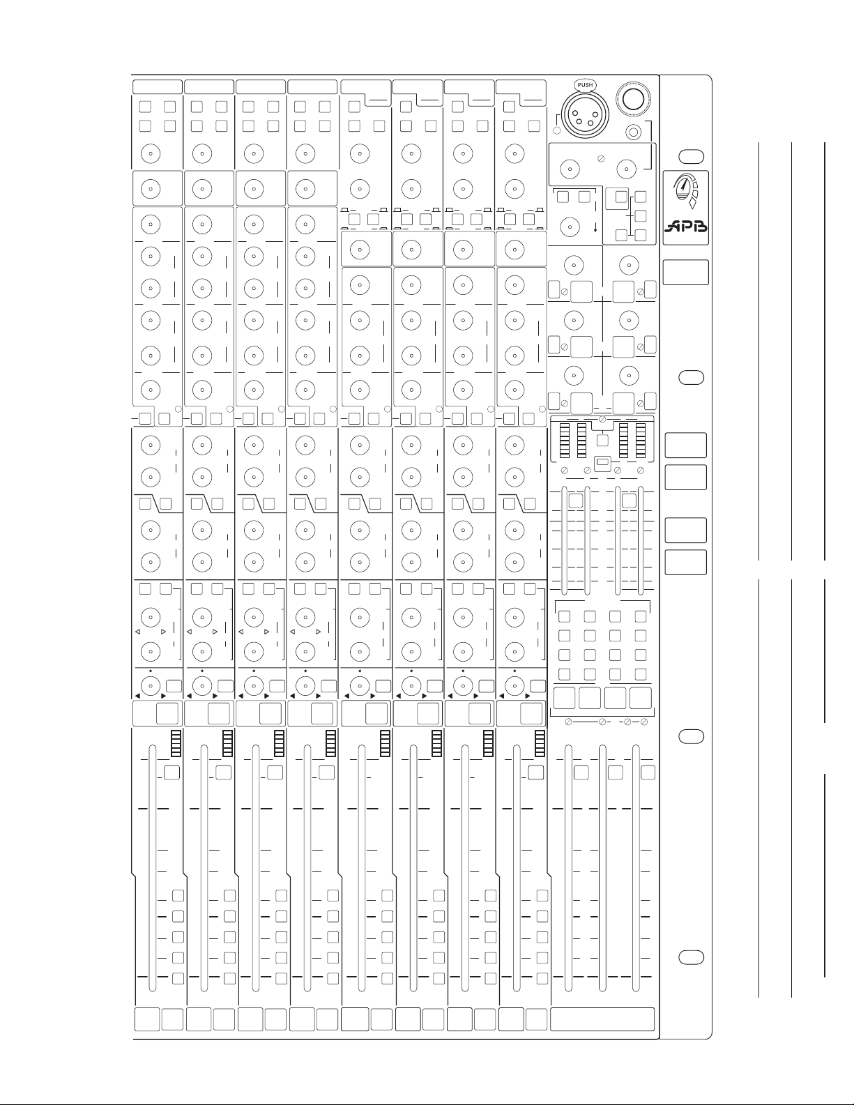
78910111213
+48V
Line
Pad
Polarity Pad
+
–
40
Gain
30
45
20
50
15
65
400
+
+
+
+
–
–
–
–
–
–
80
HPF HPF HPF HPF HPF HPF HPF
50
200
20
300
Off
–
9
Hi
Freq
15
15915
dB
2K
4K
1K
Hz
6K
8K
Hi
–
Mid
9
dB
15
15915
400
200
1K
Hz
1K5
2K
Lo
–
Mid
9
dB
15
15915
–
Lo
Freq
9
dB
15
15915
EQ
=
Pre
Fdr
On
EQ
0
6
+
12
1
3
20
6
•
Aux
0
6
+
12
2
3
20
6
•
Pre
Pre
0
6
+
12
3
3
20
6
•
Aux
0
6
+
12
4
3
20
6
•
Stereo
Pre
0
6
Pan
+
12
5
3
20
6
•
Aux
0
6
+
12
6
3
20
Lvl
6
•
Pan
6
Mute
Pk
+8
0
-6
12
Sig
10
6
5
+48V
Line
Polarity Pad
+
–
40
Gain
30
45
20
50
65
15
80
50
200
20
300
Off
400
0
+
–
9
Hi
Freq
15915
dB
2K
4K
1K
Hz
6K
8K400
Hi
0
+
–
Mid
9
dB
15915
400
200
1K
Hz
1K5
2K80
Lo
0
+
–
Mid
9
dB
15915
0
+
–
Lo
Freq
9
dB
15915
EQ
=
Pre
Fdr
On
EQ
3
–
0
6
+
12
1
3
20
6
•
Aux
3
–
0
6
+
12
2
3
20
6
•
Pre
Pre
3
–
0
6
+
12
3
3
20
6
•
Aux
3
–
0
6
+
12
4
3
20
6
•
Stereo
Pre
3
–
0
6
Pan
+
12
5
3
20
6
•
Aux
3
–
0
6
+
12
6
3
20
Lvl
6
•
Pan
7
Mute
Pk
+8
0
-6
12
Sig
10
7
5
+48V
Line
Polarity Pad
+
–
Gain
30
45
20
50
65
15
80
50
200
20
300
Off
400
0
+
–
9
Hi
Freq
15915
dB
4K
1K
Hz
6K
8K400
Hi
0
+
–
Mid
9
dB
15915
400
200
1K
Hz
1K5
2K80
Lo
0
+
–
Mid
9
dB
15915
0
+
–
Lo
Freq
9
dB
15915
EQ
Pre
Fdr
On
EQ
3
–
0
6
+
12
1
3
20
6
•
Aux
3
–
0
6
+
12
2
3
20
6
•
Pre
Pre
3
–
0
6
+
12
3
3
20
6
•
Aux
3
–
0
6
+
12
4
3
20
6
•
Stereo
Pre
3
–
0
6
Pan
+
12
5
3
20
6
•
Aux
3
–
0
6
+
12
6
3
20
Lvl
6
•
Pan
8
Mute
Pk
+8
0
-6
12
Sig
10
8
5
+48V
Line
Polarity Pad
+
–
40
Gain
30
45
20
50
65
15
80
50
200
20
300
Off
400
0
+
–
9
Hi
Freq
15915
dB
2K
4K
1K
Hz
6K
8K400
Hi
0
+
–
Mid
9
dB
15915
400
200
1K
Hz
1K5
2K80
Lo
0
+
–
Mid
9
dB
+
–
6
–
6
–
6
–
6
Stereo
–
6
–
6
15915
–
Lo
Freq
9
dB
15915
EQ
Pre
Fdr
On
EQ
0
6
+
12
1
3
20
•
Aux
0
6
+
12
2
3
20
•
Pre
Pre
0
6
+
12
3
3
20
•
Aux
0
6
+
12
4
3
20
•
Pre
0
6
Pan
+
12
5
3
20
•
Aux
0
6
+
12
6
3
20
Lvl
•
Pan
0
=
3
3
3
3
3
3
9
Mute
Pk
+8
0
-6
12
Sig
10
9
5
+48V
Line
Polarity Pad
+
–
40
Gain
30
45
20
50
65
15
80
50
200
20
300
Off
400
0
+
–
9
Hi
Freq
15915
dB
2K
4K
1K
Hz
6K
8K400
Hi
0
+
–
Mid
9
dB
15915
400
200
1K
Hz
1K5
2K80
Lo
0
+
–
Mid
9
dB
+
–
6
–
6
–
6
–
6
Stereo
–
6
–
6
15915
–
Lo
Freq
9
dB
15915
EQ
Pre
Fdr
On
EQ
0
6
+
12
1
3
20
•
Aux
0
6
+
12
2
3
20
•
Pre
Pre
0
6
+
12
3
3
20
•
Aux
0
6
+
12
4
3
20
•
Pre
0
6
Pan
+
12
5
3
20
•
Aux
0
6
+
12
6
3
20
Lvl
•
Pan
0
=
3
3
3
3
3
3
10
Mute
Pk
+8
0
-6
12
Sig
10
5
+48V
Line
40
Gain
45
50
65
200
300
400
0
+
9
Hi
Freq
dB
2K
4K
Hz
6K
8K400
Hi
0
+
Mid
9
dB
1K
Hz
1K5
2K80
Lo
0
+
Mid
9
dB
0
+
Lo
Freq
9
dB
EQ
=
3
–
0
+
3
6
Aux
3
–
0
+
3
6
Pre
3
–
0
+
3
6
Aux
3
–
0
+
3
6
Stereo
3
–
0
Pan
+
5
3
6
Aux
3
–
0
+
6
3
Lvl
6
Pan
11
Polarity Pad
+
–
30
20
50
20
1K
200
Fdr
On
EQ
12
1
20
12
2
20
Pre
12
3
20
12
4
20
Pre
12
20
12
20
40
15
80
Off
0
–
15915
2K
0
–
15915
400
0
–
15915
0
–
15915
=
Pre
3
6
•
3
6
•
3
6
•
3
6
•
3
6
•
3
6
•
65
400
+
8K400
+
2K80
+
+
–
6
–
6
–
6
–
6
Stereo
–
6
–
6
Line
Gain
45
50
200
300
9
Freq
dB
4K
6K
Mid
9
1K
1K5
Lo
Mid
9
Lo
Freq
9
EQ
0
+
3
Aux
0
+
3
Pre
0
+
3
Aux
0
+
3
0
Pan
+
3
Aux
0
+
3
Lvl
Pan
12
Mute
Pk
+8
0
-6
12
Sig
Pk
+8
0
-6
12
Sig
10
121110
5
+48V
Pol-Left
+
–
30
20
15
30
20
15
Hi
80
50
Hz
20
Off
–
Hi
15915
dB
500
Hz
–
dB
15915
–
dB
15915
Pre
Fdr
On
EQ
6
12
1
20
•
6
12
2
20
•
Pre
6
12
3
20
•
6
12
4
20
•
Pre
6
12
5
20
•
6
12
6
20
•
+48V
Stereo
Pad
(Line)
Pol-Left
+
–
40
Gain
30
45
L
20
50
65
40
Stereo
Mono
0
1K
0
0
=
3
3
3
3
3
3
15
Gain
30
45
R
20
50
65
15
RL
HPF HPF HPF HPF
50
200
20
300
Off
400
+
9
Hi
Freq
15915
dB
500
2K
Hz
4K
6K200
Mid
+
9
dB
15915
+
Lo
Freq
9
dB
15915
EQ
Pre
Fdr
On
EQ
–
0
6
+
12
1
3
20
6
•
Aux
–
0
6
+
12
2
3
20
6
•
Pre
Pre
–
0
6
+
12
3
3
20
6
•
Aux
–
0
6
+
12
4
3
20
6
•
Stereo
Pre
–
0
6
L
+
12
5
3
20
6
•
Aux
–
0
6
+
12
6
3
20
R
6
•
Bal
14
Dual-Mono
13
Mute
10
5
Mute
Pk
0
L
Sig
Pk
R
0
Sig
10
13
5
15
Dual-Mono Dual-Mono Dual-Mono
+48V
Stereo Stereo Stereo
Pad
(Line)
Pol-Left
+
–
40
Gain
30
45
L
20
50
65
65
400
+
6K200
+
+
–
6
–
6
–
6
–
6
–
6
–
6
45
50
200
300
9
2K
4K
9
9
EQ
0
0
Pre
0
0
Stereo
0
0
Bal
+
3
+
3
+
3
+
3
+
3
+
3
Gain
Freq
Freq
Aux
Aux
Aux
15
30
R
20
15
RL
50
20
Off
Hi
15915
dB
500
Hz
Mid
dB
15915
Lo
dB
15915
Pre
Fdr
On
EQ
6
12
1
20
•
6
12
2
20
•
Pre
6
12
3
20
•
6
12
4
20
•
Pre
6
L
12
5
20
•
6
12
6
20
R
•
40
Stereo
Stereo
Mono
80
0
–
1K
0
–
0
–
=
3
3
3
3
3
3
14
Mute
Pk
0
L
Sig
Pk
R
0
Sig
10
14
5
16
+48V
Pad
(Line)
Pol-Left
+
–
40
Gain
30
45
L
20
50
65
40
Gain
30
45
R
20
50
65
Stereo
RL
Mono
80
50
200
20
300
Off
400
0
+
–
9
Hi
Freq
15915
dB
1K
500
2K
Hz
4K
6K200
Mid
0
+
–
9
dB
15915
0
+
–
Lo
Freq
9
dB
15915
EQ
=
3
3
3
3
3
3
–
–
–
–
–
–
0
6
0
6
0
6
0
6
Stereo
0
6
0
6
Pre
Fdr
On
EQ
6
+
12
1
3
20
Aux
6
+
12
2
3
20
Pre
Pre
6
+
12
3
3
20
Aux
6
+
12
4
3
20
Pre
6
L
+
12
5
3
20
Aux
6
+
12
6
3
20
R
Bal
15
Mute
Pk
0
L
Sig
Pk
R
0
Sig
10
15
5
Pad
(Line)
Inten
40
Gain
45
L
Monitor Out
50
3
65
15
15
80
–
–
–
•
•
•
•
•
•
40
Stereo
Mono
0
1K
0
0
=
3
3
3
3
3
3
65
400
+
+
+
–
–
–
–
–
–
45
50
200
300
2K
4K
6K200
EQ
0
+
6
0
+
6
Pre
0
+
6
0
+
6
Stereo
0
+
6
0
+
6
Bal
9
9
9
3
3
3
3
3
3
Gain
Aux
Aux
Aux
Freq
Mid
Freq
R
Hi
dB
Hz
dB
Lo
dB
L
5
6
R
RL
On
1
2
3
4
218
C
Stereo Alt Out
3
218
12
20
Aux
1
12
20
Aux
3
12
20
Aux
5
16
Pk
0
L
Sig
Pk
R
0
Sig
16
12V
Lamp
2
Phones
Power
Phones
On
5
6
4
7
9
100
5
4
6
7
9
100
3
–
0
6
10
•
3
–
0
6
10
•
3
–
0
6
10
•
12 34
9
6
3
0
3
6
12
24
MC L R
12 34
Grp
1 2
ProRack
H1020
M
Add
To
L-R
A1
Out
+
6
AFL
A3
Out
+
6
AFL
A5
Out
+
6
AFL
Groups
Meter Select
Solo
Aux
5-6
Str
Sig
10
5
0
5
4
3
218
Ext
In
(Only)
Source
Select
(Mixed)
6
12
20
•
6
12
20
•
6
12
20
•
5
6
7
9
100
M
C
L-R
3
–
A2
0
Out
+
6
10
Aux
2
3
–
A4
0
Out
+
6
10
Aux
4
3
–
A6
0
Out
+
6
10
Aux
6
9
6
3
0
3
6
12
24
Grp
3 4
10
20
30
Group
Level
Group Assign
1234
M
C
L
R
1234
MCLR
10
ML
M
C
L
R
Grp
AFL
Sig
10
-
C
R
DynaSonics
ProRack
H1020
APB-DynaSonics
ProRack-FOH
Track Sheet
G1
G2
G3
G4
0
5
10
M
15
C
20
L-R
30
1-2
40
3-4
0
5
10
M
15
C
20
L-R
30
1-2
40
3-4
0
5
10
M
15
C
20
L-R
30
1-2
40
3-4
0
5
10
M
15
C
20
L-R
30
1-2
40
3-4
0
5
10
M
15
C
20
L-R
30
1-2
40
3-4
0
5
10
M
15
C
20
L-R
30
1-2
40
3-4
0
5
10
M
15
C
20
L-R
30
1-2
40
3-4
0
5
10
M
15
C
20
L-R
30
1-2
40
3-4
0
5
10
M
15
C
20
L-R
30
1-2
40
3-4
0
5
10
M
15
C
20
L-R
30
1-2
40
3-4
PFL PFL PFL PFL PFL PFL PFL PFL PFL PFL PFL
7 8 9 10 11 12 13 14 15 16
M
C
L-R
1-2
3-4
MCL-R
0
0
5
5
10
10
15
15
20
20
30
30
40
40
Artist
Song
Engineer Date
Page 36

36
Page 37
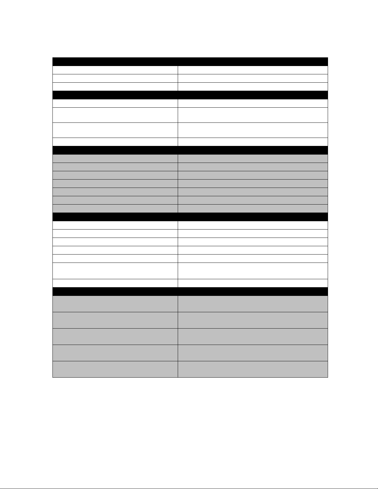
TECHNICAL SPECIFICATIONS
General Specifications
Frequency Response (any input to any output) +0/-0.5dB 20Hz to 20kHz (ref to 1kHz)
THD + Noise (Mic Input to Main Output) <0.01% @ +15dBu output
Phase Response (Mic Input to Main Output) +10/-15 degrees 20Hz to 20kHz (ref to 1kHz)
Noise
Mic EIN -128dBu @ 60dB gain, 150Ω source
Main Bus (L-R-C-M) Output Noise
Group Bus (1-4) Output Noise -85dBu (All Chan assigned w/faders down, Group Master
Aux Bus (1-6) Output Noise -90dBu (Aux Sends down, Aux Master at unity)
Crosstalk (measured at 1KHz)
Channel Mute >100dB
Channel Fader Attenuation >100dB
Channel Routing >80dB
Channel Pan Isolation >80dB
Channel to Channel Isolation >90dB
Aux Send Attenuation >90dB
Aux Pan Isolation >70dB
Input / Output Impedance
Channel XLR Input >3KΩ Balanced (with or without Pad)
Channel Line Input (via TRS) >20KΩ Balanced
Channel Line Input (via XLR w/Pad) >4KΩ Balanced
Channel TRS Direct Out 100Ω Impedance-Balanced
Bus XLR Outputs (Main, Group, Aux) 100Ω Symmetrically-Balanced (To Feed 600Ω or greater)
Channel and Bus Insert Sends/Returns 100Ω Unbalanced / 5KΩ Unbalanced
Monitor TRS Outputs 100Ω Impedance-Balanced
Input / Output Levels
Channel Insert +4dBu (Tip= Send, Ring= Return, Sleeve= Audio Gnd)
Channel Direct Out +4dBu (TRS Impedance Balanced, Tip= “Hot”)
XLR Balanced Outs +4dBu (Symmetrically-Balanced, Pin 2= “Hot”)
TRS Balanced Outs +4dBu (Impedance-Balanced, Tip= “Hot”)
Bus Insert -2dBu (Tip= Send, Ring= Return, Sleeve= Audio Gnd)
-85dBu (All channels assigned w/faders down, Master faders
at unity)
fader at unity)
(To Feed 2kΩ or greater)
Max Out= +22dBu
Max Out= +22dBu
Max Out= +26dBu
Max Out= +22dBu
Max Out= +22dBu
37
Page 38

APB-DynaSonics ProRack-FOH Owners Manual ver 0.92
 Loading...