

Page 1
ZONE4
Instruction manual
Page 2

Page 3
ZONE4 Manual
Instruction manualZONE4
1
Page 4

2
Pre-Amplifiers
Safety information
• Please check the carton box for any kind of damage on
reception of the goods. In case of a damaged carton, please
contact your dealer before opening the carton.
• !!!! Danger !!!! Exposure to extremely high noise levels may
cause a permanent hearing loss. Individuals vary considerably to
noise induced hearing loss but nearly everyone will lose some
hearing if exposed to sufficiently intense noise for a sufficient
amount of time. Therefore it is recommended that all persons
exposed to equipment capable of producing high sound
pressure levels, such as this amplifier, be protected by hearing
protection while installing or operating this unit.
• Read all documentation before operating your equipment.
• Keep all documentation for future reference.
• Save the carton and packing material even if the equipment has
arrived in good condition.
• Should you ever need to ship the unit, use only the original
factory packing.
• Do not spill water or other liquids into or on the unit.
• Make sure power outlets conform to the power requirements
listed on the back of the unit.
• Do not use the unit if the electrical power cord is frayed or
broken.
• Have gain controls on amplifiers turned down during power-up
to prevent speaker damage if there are high signal levels at the
inputs.
Page 5

Instruction manualZONE4
• Do not connect the inputs / outputs of amplifiers or consoles
to any other voltage source, such as a battery, mains source, or
power supply, regardless of whether the amplifier or console is
turned on or off.
• Power down & disconnect units from mains voltage before
making connections.
• Do not use the unit near stoves, heat registers, radiators, or
other heat producing devices.
• Do not remove the cover. Removing the cover will expose you
to potentially dangerous voltages.
• In case of mal-function this device should be serviced by
qualified service personnel only.
3
Page 6

4
Pre-Amplifiers
Introduction
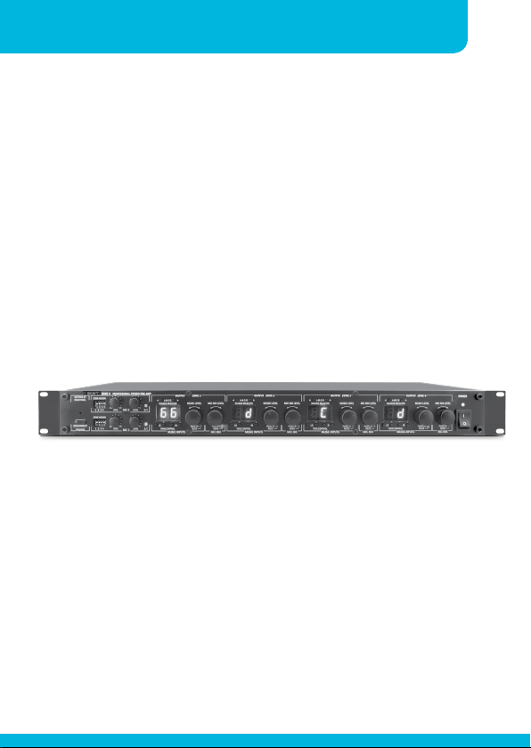
Zone 4 professional preamp has 4 stereo line source inputs on RCA
connectors plus 3 mono mic/line balanced inputs on euroblocks. All
mic inputs feature individual sensitivity, level and tone control. Mic
2 and 3 inputs have switchable phantom power. Each mic signal
can be assigned to any of the 4 available zone outputs.Microphone
input 1 controls and connectors are available at the rear of the
unit, featuring a balanced mic input with priority switch and zone
assign preset dipswitches. If you need more flexibility and ease
of installation, simply connect our Apart selective paging station
MICPAT-4 instead, it will override the mic 1 zone assignments. Mic
2 and 3 inputs can be controlled and assigned via the front panel
controls. In order to avoid any abuse by the end user, you can hide
the microphone controls with the supplied cover plate.
Zone 1 to 4 stereo outputs can be individually configured as mono
or stereo outputs and are available on RCA connectors. Every zone
has its own line input selector, bass and treble tone control and
music level control. Every zone also has its own microphone mix
level control. Music and mic mix can be muted/unmuted manually
per zone by simply pushing the level knob.
System integrators will be pleased to find a RS232 port at the back,
allowing full control of the most important system parameters.
If you need to control the zones locally, you can always add a wired
remote, Apart model ZONE4R to any zone. Wiring is simple, using
standard RJ45 connectors and CAT5 cable.
Finally there is the IR input port. This port can be used to connect
our optional PIR-REC infrared receiver. There is no infrared remote
control available for the ZONE4 unit. We have added the infrared
codes for those who want to program their universal infrared
control unit.
Page 7
Instruction manualZONE4
Front panel
5 7
6
11 15 17
8
13
10
12
16
18
14
3 9
2
1
4
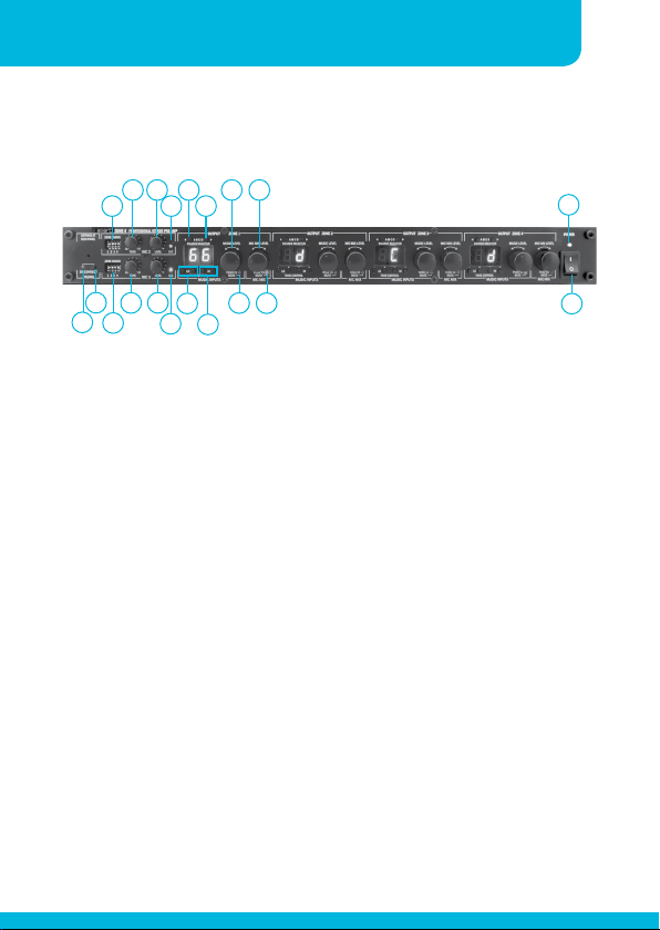
1. Disconnect paging led: this led is lit when you push the
disconnect paging button ‘2’.
2. Disconnect paging button: push this button to disable the
paging function. This can be convenient in case you want to
avoid accidental paging and thus muting of the line inputs.
Note that mic 2 and mic 3 are still active. The paging button(s)
will not mute the music (or line signals). Mic 1 will be entirely
disabled.
3. Zone assign dipswitches mic 2: with these dipswitches you can
assign the mic 2 signal to zone 1 to 4.
4. Zone assign dipswitches mic 3: with these dipswitches you can
assign the mic 3 signal to zone 1 to 4.
5
20
19
5. Mic 2 tone control: turn the knob to darken the tone (turn to
the left) or to brighten the tone (turn to the right).
6. Mic 3 tone control: turn the knob to darken the tone (turn to
the left) or to brighten the tone (turn to the right).
7. Mic 2 level control: turn the knob to the right to increase mic 2
Page 8

6
Pre-Amplifiers
level or to the left to reduce the level.
8. Mic 3 level control: turn the knob to the right to increase mic 3
level or to the left to reduce the level.
9. Mic signal/clip led: this led is green when a signal is present on
mic 2 input and is red when the input is overloaded. Reduce
the gain knob at the rear to avoid overload and distortion.
10. Mic signal/clip led: this led is green when a signal is present on
mic 3 input and is red when the input is overloaded. Reduce
the gain knob at the rear to avoid overload and distortion.
11. Zone 1 line input selector switches: use these switches to scroll
through line input A to D. The selected input is shown in the
display ‘12’ as A, b, C, d.
12. Multifunctional 7 segment LED display: this display shows the
currently selected line input. When you change the mic or
music level by turning the knobs 15 or 17, the actual level is
shown in the display for a few seconds.
13. Lo tone control: push the + or – buttons to increase or decrease
the bass tones in zone 1. This tone control has no influence
on the mic tone control and will adjust the tone on line signals
only.
14. Hi tone control: push the + or – buttons to increase or decrease
the high tones in zone 1. This tone control has no influence
on the mic tone control and will adjust the tone on line signals
only.
15. Zone 1 music level control: turn this knob to adjust the zone 1
music level. If you push this button, the music will be muted.
Pushing a second time will unmute the music signal in zone 1.
This is indicated by led ‘16’.
Page 9

Instruction manualZONE4
16. Music mute led: this led lights up when the music in zone 1 is
muted by pushing the ‘15’ knob or by activating paging.
17. Mic mix level control zone 1: turn this knob to adjust the zone
1 mic mix level. If you push this button, the mic mix signal will
be muted. Pushing a second time will unmute the mic mix
signal in zone 1. This is indicated by led ‘18’.
18. Mic mix mute led: this led lights up when the mic mix in zone 1
is muted by pushing the ‘17’ knob. Please note that this will not
disable the paging function of the mics, in other words : if the
microphone signal is muted, but when paging is activated, the
music level will be muted also, unless you activate disconnect
paging (button ‘2’).
19. On/off switch: flip this switch to turn the unit on or off.
20. Power led: this led is lit when the power is on. When the unit is
set to stand-by via RS232, then this led will still be lit to indicate
that mains power is still present.
7
Page 10
8
Back panel
Pre-Amplifiers
1
2 4 6
5
3
7 8 9
11
12
10
16
13
15
14
21
25
30
27
23
18
20
19
17
28
24
26 29
22
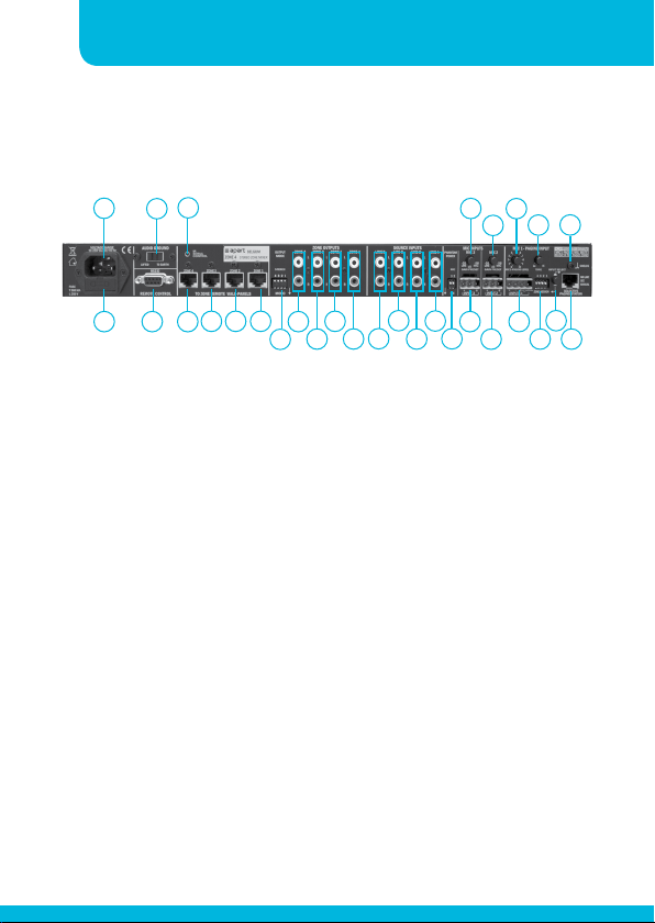
1. Mains inlet socket: connect the supplied mains cable here, the
internal power supply is self adjusting and accepts AC voltages
between 90 up to 260 VAC, 50 and 60 Hz.
2. Mains fuse: if the fuse blows, replace it with the same value
and voltage rating, in this case : T500mA L250V.
3. Audio GND/Lift switch: use this switch to isolate the audio
ground from the electrical ground. This is a handy feature to
find ground loops and to avoid hum in your audio signal.
4. RS232 connector: connect your serial cable here. For details,
refer to the separate serial communication section.
5. IR bus: input for optional PIR-REC infrared receiver. Please note
that no handheld infrared transmitter is available for Zone 4.
6. Zone 4 remote panels connector: connect the separately
available wired remote here. This is a standard RJ45 connector
for Zone 4 remote wall panels only. Never connect this to
a computer or other network. Damage caused by poor or
incorrect installation is excluded from the warranty. Up to 8 pcs.
ZONE4R remote panels can be connected to a single ZONE4.
Page 11

Instruction manualZONE4
More than 1 panel per zone can be used. Please refer to the
ZONE4R manual.
7. Same as described in 6.
8. Same as described in 6.
9. Same as described in 6.
10. Output mode selector switch: here you can configure the
individual zone outputs for mono or stereo operation. In case of
mono, the same ‘stereo mixed into mono’ signal is present on
the zone left and right connectors.
11. Zone 4 output connector on cinch connectors.
12. Zone 3 output connector on cinch connectors.
13. Zone 2 output connector on cinch connectors.
14. Zone 1 output connector on cinch connectors.
15. Source D line level input on cinch connectors.
16. Source C line level input on cinch connectors.
17. Source B line level input on cinch connectors.
9
18. Source A line level input on cinch connectors.
19. Mic 2/3 phantom power switch.
20. Mic 3 balanced input on euroblock connector.
21. Mic 3 gain control: from mic level to line level (e.g. wireless
microphone receivers).
Page 12

10
Pre-Amplifiers
22. Mic 2 balanced input on euroblock connector.
23. Mic 2 gain control: from mic level to line level (e.g. wireless
microphone receivers).
24. Mic 1 balanced input connector with paging switch possibility.
The paging contact can also be used for mic 2 and 3. Closing
this contact mutes the music.
25. Mic 1 level control.
26. Mic 1 zone assign switch.
27. Mic 1 tone control.
28. Mic 1 input selector: push the switch in/out to select the mic
connector on euroblock or the MICPAT-4 selective paging
station.
29. RJ45 connector for the MICPAT-4 selective paging station only.
Up to 4 pcs. of MICPAT-4 can be connected to a single ZONE4.
A smart bus-sytem arranges the Priority (busy-line). Please refer
to the MICPAT4 manual.
30. Additional GND connecting screw.
Page 13
Instruction manualZONE4
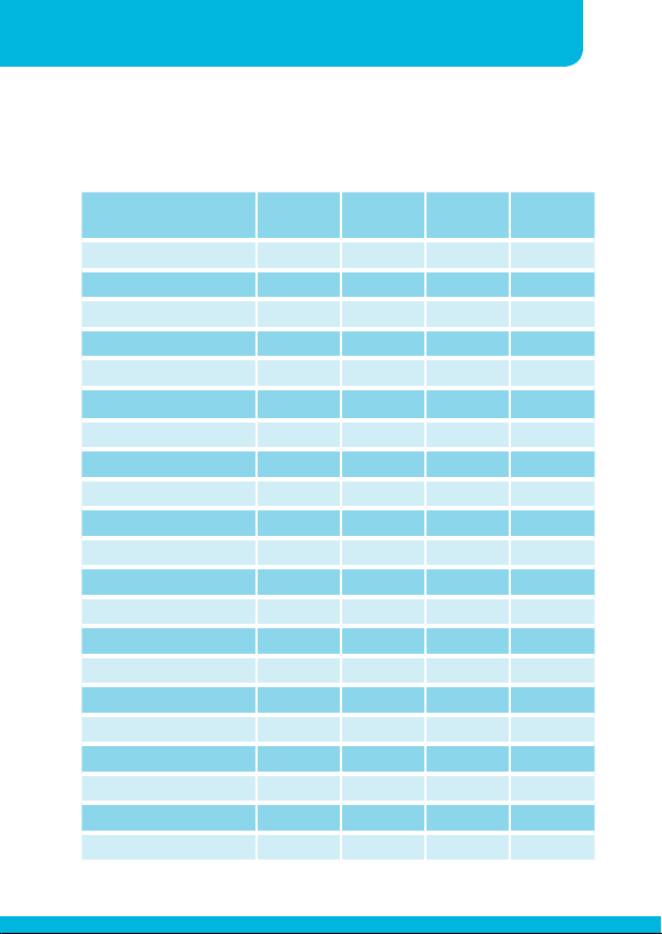
ZONE4 INFRARED CONTROL CODES*
11
IR FUNCTIONS ZONE LEAD
CODE
MUSIC VOLUME UP ZONE 1 9MS 04FB 83
MUSIC VOLUME DOWN ZONE 1 9MS 04FB 87
MIC VOLUME UP ZONE 1 9MS 04FB 82
MIC VOLUME DOWN ZONE 1 9MS 04FB 86
SELECT SOURCE A ZONE 1 9MS 04FB 11
SELECT SOURCE B ZONE 1 9MS 04FB 12
SELECT SOURCE C ZONE 1 9MS 04FB 13
SELECT SOURCE D ZONE 1 9MS 04FB 14
MUSIC VOLUME UP ZONE 2 9MS 04FB 8B
MUSIC VOLUME DOWN ZONE 2 9MS 04FB 8F
MIC VOLUME UP ZONE 2 9MS 04FB 8A
MIC VOLUME DOWN ZONE 2 9MS 04FB 8E
SELECT SOURCE A ZONE 2 9MS 04FB 15
SELECT SOURCE B ZONE 2 9MS 04FB 16
SELECT SOURCE C ZONE 2 9MS 04FB 17
SELECT SOURCE D ZONE 2 9MS 04FB 18
MUSIC VOLUME UP ZONE 3 9MS 04FB 93
MUSIC VOLUME DOWN ZONE 3 9MS 04FB 97
MIC VOLUME UP ZONE 3 9MS 04FB 92
MIC VOLUME DOWN ZONE 3 9MS 04FB 96
SELECT SOURCE A ZONE 3 9MS 04FB 21
DEVICE ID
CODE
DATA
CODE
Page 14
12
Pre-Amplifiers
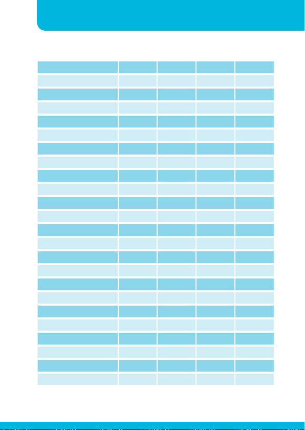
Select source B ZONE 3 9MS 04FB 22
Select source C ZONE 3 9MS 04FB 23
Select source D ZONE 3 9MS 04FB 24
Music volume UP ZONE 4 9MS 04FB 9B
Music volume down ZONE 4 9MS 04FB 9F
Mic volume up ZONE 4 9MS 04FB 9A
Mic volume down ZONE 4 9MS 04FB 9E
Select source A ZONE 4 9MS 04FB 25
Select source B ZONE 4 9MS 04FB 26
Select source C ZONE 4 9MS 04FB 27
Select source D ZONE 4 9MS 04FB 28
Mute music ZONE1 9MS 04FB 81
Un-mute music ZONE1 9MS 04FB 1A
Mute mic ZONE1 9MS 04FB 8C
Un-mute mic ZONE1 9MS 04FB 1B
Mute music ZONE 2 9MS 04FB 89
Un-mute music ZONE 2 9MS 04FB 1C
Mute mic ZONE 2 9MS 04FB 90
Un-mute mic ZONE 2 9MS 04FB 1D
Mute music on/off ZONE 3 9MS 04FB 91
Un-mute music ZONE 3 9MS 04FB 2A
Mute mic on/off ZONE 3 9MS 04FB 98
Un-mute mic ZONE 3 9MS 04FB 2B
Mute music on/off ZONE 4 9MS 04FB 99
Page 15
Instruction manualZONE4
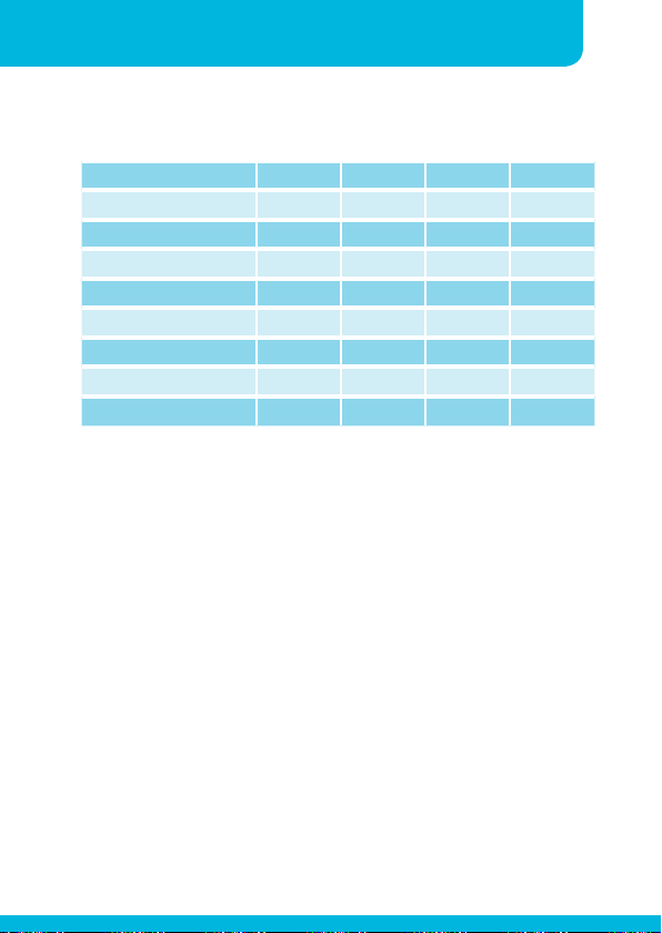
Un-mute music ZONE 4 9MS 04FB 2C
Mute mic on/off ZONE 4 9MS 04FB 88
Un-mute mic ZONE 4 9MS 04FB 2D
Disconnect paging (on) 9MS 04FB 84
Connect paging (off) 9MS 04FB 2E
Source up ZONE 1 9MS 04FB 85
Source up ZONE 2 9MS 04FB 8D
Source up ZONE 3 9MS 04FB 95
Source up ZONE 4 9MS 04FB 9D
Command structure : ZONE4 ID code –> command –> inverse
command.
13
Page 16
14
Pre-Amplifiers
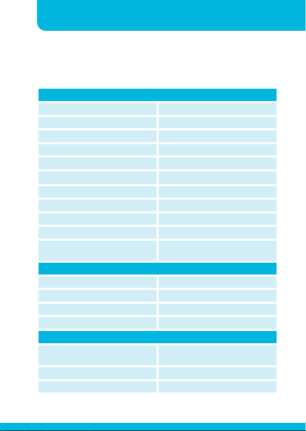
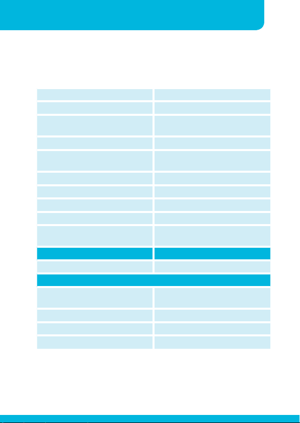
TECHNICAL SPECIFICATIONS
Outputs
Output stereo zone 1 unbalanced Cinch connector 0dB, 1 V, 100 ohm
Output stereo zone 2 unbalanced Cinch connector 0dB, 1 V, 100 ohm
Output stereo zone 3 unbalanced Cinch connector 0dB, 1 V, 100 ohm
Output stereo zone 4 unbalanced Cinch connector 0dB, 1 V, 100 ohm
Frequency response 20 HZ - 30 kHz
S/N Ratio > 90dB
THD < 0,02 %
Crosstalk > 75 dB
Max nominal gain +5 dB
Max output voltage +13 dBV, 4.5 V
Tone control zone 1 to 4 Bass 75 Hz +/-10 dB treble 10 kHz
Line inputs
Line A to D Cinch connectors L & R channel
Line A to D sensitivity 0 dBV, 1V
Line A to D impedance 100 kOhm
Line A to D max input level +8 dBV
Mic/line inputs
Input mic/line 1 Balanced on euroblock connectors
Input mic/line 1 sensitivity Mic: 3mV / -50dBV Line: 2V / 6 dBV
Input mic/line 1 impedance 2 kOhm / 11 kOhm
+/- 10 dB
/ RJ45
Page 17
Instruction manualZONE4
Input mic/line 1 max input level -43 dBV / 18 dBV
Input mic/line 2 and 3 Balanced on euroblock connectors
Input mic/line 2 and 3 sensitivity Trim from 1,5mV / -56 dBV TO 150
Input mic/line 2 and 3 impedance 15 kOhm
Input mic/line 2 and 3 max input
level
CMRR > 50 dB
S/N Ratio > 65 dB @ MIC level 4 mV
THD < 0.09 %
Phantom power mic 2 and 3 18 V, individually switchable
Tone control mic/line 1 to 3 From 100 Hz / +3 dB,10 kHz / -6 dB
Remote control Via RJ45 CAT5 per zone
Optional models
General
Power supply 90 to 260 VAC / 50 - 60 Hz auto
Dimensions w x d x h 420 (484) X 190 (210) X 44 mm
Shipping weight 2.4 kg
Net weight 1.6 kg
mV / -16 dBV
-38 dBV to -1 dBV (gain max - min)
to 100 Hz / -9 dB, 10 kHz / +4 dB
ranging
15
Page 18
16
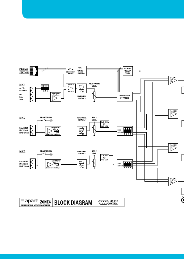
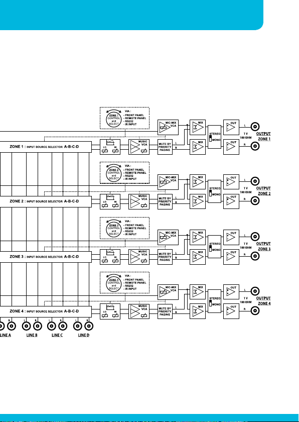
Block diagram
Pre-Amplifiers
Page 19
Instruction manualZONE4
17
Page 20

18
Pre-Ampliers
RS232 commands
IC245 (ZONE4) ASCII (090915)
Protocol:
Baud rate : 9600 bps
Data Bit : 8 bits
STOP Bit : 1 bit
Parity : None
Flow Cntrl : No
Command String ASCII String Hexadecimal
ALL
Power On $hPW1 24 68 50 57 31
Power Off $hPW2 24 68 50 57 32
DISCON LED On $hPW3 24 68 50 57 33
DISCON LED Off $hPW4 24 68 50 57 34
PAGE1 On $hPW5 24 68 50 57 35
PAGE1 Off $hPW6 24 68 50 57 36
PAGE2 On $hPW7 24 68 50 57 37
PAGE2 Off $hPW8 24 68 50 57 38
PAGE3 On $hPW9 24 68 50 57 39
PAGE3 Off $hPWa 24 68 50 57 41
PAGE4 On $hPWB 24 68 50 57 42
PAGE4 Off $hPWC 24 68 50 57 43
CH1 MUTE On $aM01 24 61 4D 30 31
CH1 MUTE Off $aM02 24 61 4D 30 32
CH2 MUTE On $bM01 24 62 4D 30 31
CH2 MUTE Off $bM02 24 62 4D 30 32
CH3 MUTE On $cM01 24 63 4D 30 31
CH3 MUTE Off $cM02 24 63 4D 30 32
CH4 MUTE On $dM01 24 64 4D 30 31
CH4 MUTE Off $dM02 24 64 4D 30 32
Page 21

ZONE4 Instruction manual
Command String ASCII String Hexadecimal
CH1 MIC MUTE On $aM03 24 61 4D 30 33
CH1 MIC MUTE Off $aM04 24 61 4D 30 34
CH2 MIC MUTE On $bM03 24 62 4D 30 33
CH2 MIC MUTE Off $bM04 24 62 4D 30 34
CH3 MIC MUTE On $cM03 24 63 4D 30 33
CH3 MIC MUTE Off $cM04 24 63 4D 30 34
CH4 MIC MUTE On $dM03 24 64 4D 30 33
CH4 MIC MUTE Off $dM04 24 64 4D 30 34
CH1 VOL UP $avup 24 61 76 75 70
CH1 VOL DOWN $avdn 24 61 76 64 6E
CH2 VOL UP $bvup 24 62 76 75 70
CH2 VOL DOWN $bvdn 24 62 76 64 6E
CH3 VOL UP $cvup 24 63 76 75 70
CH3 VOL DOWN $cvdn 24 63 76 64 6E
CH4 VOL UP $dvup 24 64 76 75 70
CH4 VOL DOWN $dvdn 24 64 76 64 6E
CH1 MICVOL UP $acup 24 61 63 75 70
CH1 MICVOL DOWN $acdn 24 61 63 64 6E
CH2 MICVOL UP $bcup 24 62 63 75 70
CH2 MICVOL DOWN $bcdn 24 62 63 64 6E
CH3 MICVOL UP $ccup 24 63 63 75 70
CH3 MICVOL DOWN $ccdn 24 63 63 64 6E
CH4 MICVOL UP $dcup 24 64 63 75 70
CH4 MICVOL DOWN $dcdn 24 64 63 64 6E
CH1 VOL $aV79 24 61 56 37 39
CH1 VOL $aV01 24 61 56 30 31
CH2 VOL $bV?? 24 62 56 3? 3?
CH3 VOL $cV?? 24 63 56 3? 3?
CH4 VOL $dV?? 24 64 56 3? 3?
19
Page 22

20
Pre-Ampliers
RS232 commands
Command String ASCII String Hexadecimal
CH1 MICVOL $aC79 24 61 43 37 39
CH1 MICVOL $aC01 24 61 43 30 31
CH2 MICVOL $bC?? 24 62 43 3? 3?
CH3 MICVOL $cC?? 24 63 43 3? 3?
CH4 MICVOL $dC?? 24 64 43 3? 3?
CH1 FUN_1 $aS04 24 61 53 30 34
CH1 FUN_2 $aS03 24 61 53 30 33
CH1 FUN_3 $aS02 24 61 53 30 32
CH1 FUN_4 $aS01 24 61 53 30 31
CH2 FUN_1 $bS04 24 62 53 30 34
CH2 FUN_2 $bS03 24 62 53 30 33
CH2 FUN_3 $bS02 24 62 53 30 32
CH2 FUN_4 $bS01 24 62 53 30 31
CH3 FUN_1 $cS04 24 63 53 30 34
CH3 FUN_2 $cS03 24 63 53 30 33
CH3 FUN_3 $cS02 24 63 53 30 32
CH3 FUN_4 $cS01 24 63 53 30 31
CH4 FUN_1 $dS04 24 64 53 30 34
CH4 FUN_2 $dS03 24 64 53 30 33
CH4 FUN_3 $dS02 24 64 53 30 32
CH4 FUN_4 $dS01 24 64 53 30 31
CH1 TRE $aT 7 24 61 54 20 37
CH1 TRE $aT 6 24 61 54 20 36
CH1 TRE $aT 5 24 61 54 20 35
CH1 TRE $aT 4 24 61 54 20 34
CH1 TRE $aT 3 24 61 54 20 33
CH1 TRE $aT 2 24 61 54 20 32
CH1 TRE $aT 1 24 61 54 20 31
CH1 TRE $aT 0 24 61 54 20 30
CH1 TRE $aT-1 24 61 54 2D 31
CH1 TRE $aT-2 24 61 54 2D 32
CH1 TRE $aT-3 24 61 54 2D 33
CH1 TRE $aT-4 24 61 54 2D 34
CH1 TRE $aT-5 24 61 54 2D 35
CH1 TRE $aT-6 24 61 54 2D 36
CH1 TRE $aT-7 24 61 54 2D 37
Page 23

ZONE4 Instruction manual
Command String ASCII String Hexadecimal
CH2 TRE $bT 0 24 62 54 20 30
…
CH3 TRE $cT 0 24 63 54 20 30
…
CH4 TRE $dT 0 24 64 54 20 30
…
CH1 BAS $aU 7 24 61 55 20 37
CH1 BAS $aU 6 24 61 55 20 36
CH1 BAS $aU 5 24 61 55 20 35
CH1 BAS $aU 4 24 61 55 20 34
CH1 BAS $aU 3 24 61 55 20 33
CH1 BAS $aU 2 24 61 55 20 32
CH1 BAS $aU 1 24 61 55 20 31
CH1 BAS $aU 0 24 61 55 20 30
CH1 BAS $aU-1 24 61 55 2D 31
CH1 BAS $aU-2 24 61 55 2D 32
CH1 BAS $aU-3 24 61 55 2D 33
CH1 BAS $aU-4 24 61 55 2D 34
CH1 BAS $aU-5 24 61 55 2D 35
CH1 BAS $aU-6 24 61 55 2D 36
CH1 BAS $aU-7 24 61 55 2D 37
CH2 BAS $bU 0 24 62 55 20 30
…
CH3 BAS $cU 0 24 63 55 20 30
…
CH4 BAS $dU 0 24 64 55 20 30
…
21
Page 24

22
Pre-Ampliers
RS232 commands
Request String ASCII String Hexadecimal
Power Status $aR 1 24 61 52 20 31
ACK
Power On $hPW1 24 68 50 57 31
Power Off $hPW2 24 68 50 57 32
CH1 Mute Status $aR 2 24 61 52 20 32
ACK
CH1 MUTE On $aM01 24 61 4D 30 31
CH1 MUTE Off $aM02 24 61 4D 30 32
CH1 TREBLE Status $aR 3 24 61 52 20 33
ACK
CH1 TREBLE $aT 0 24 61 54 20 30
CH1 BASS Status $aR 4 24 61 52 20 34
ACK
CH1 BASS $aU 0 24 61 55 20 31
CH1 SOURCE Status $aR 5 24 61 52 20 35
ACK
CH1 SOURCE $aS04 24 61 53 30 34
CH1 VOL Status $aR 6 24 61 52 20 36
ACK
CH1 VOL $aV?? 24 61 56 3? 3?
CH1 MICVOL Status $aR 7 24 61 52 20 37
ACK
CH1 MICVOL $aC?? 24 61 43 3? 3?
CH1 MICVOL Status $aR 8 24 61 52 20 38
ACK
CH1 MICMUTE ON $aM03 24 61 4D 30 33
CH1 MICMUTE OFF $aM04 24 61 4D 30 34
CH1 MICVOL Status $aR 9 24 61 52 20 39
ACK
CH1 PAGE ON $hPW5 24 68 50 57 35
CH1 PAGE OFF $hPW6 24 68 50 57 36
Page 25

developed
by
Industriepark Brechtsebaan 8 bus 1
Audioprof nv
2900 Schoten - Belgium
Company names, product names and trademarks are property of their
Apart-Audio specifications are subject to change without notice.
respective owners.
 Loading...