

Page 1
REVAMP2250
Instruction manual
Page 2

Page 3
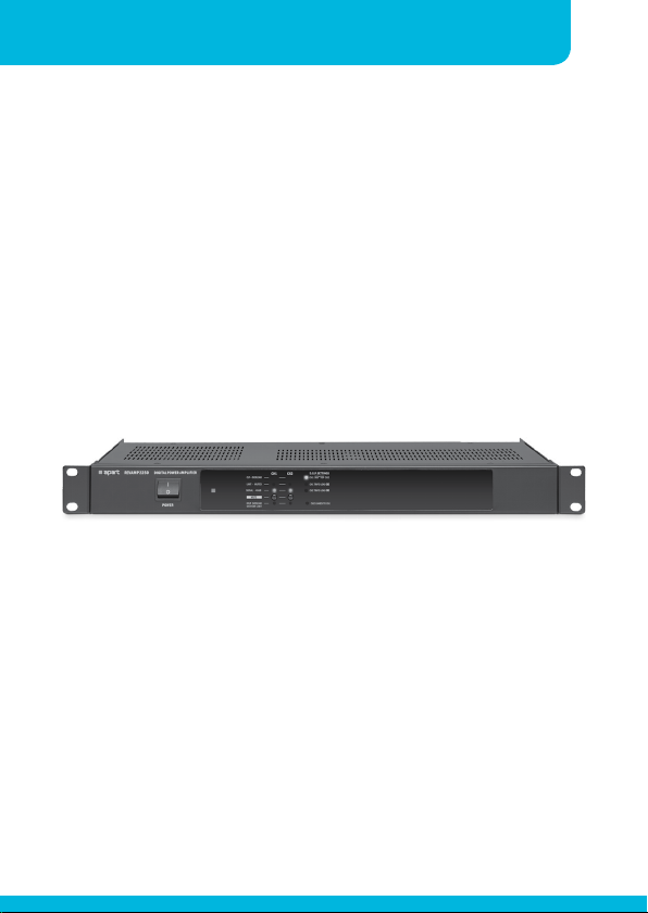
REVAMP2250 Manual
Instruction manualREVAMP2250
3
Page 4

4
CLASS-D POWER AMPLIFIER
IMPORTANT SAFETY INSTRUCTIONS
1. Read these instructions
2. Keep these instructions
3. Heed all warnings
4. Follow all instructions
5. This professional device needs to be installed by qualified personnel only.
6. Danger: Exposure to high sound levels may cause a permanent hearing
loss. Individuals vary considerably to sound pressure level induced
hearing loss but nearly everyone will lose some hearing if exposed to
high sound pressure levels for a sufficient amount of time. Therefore
it is recommended that all persons exposed to equipment capable of
producing high sound pressure levels, such as this amplifier, be protected
by hearing protection while installing or operating this unit.
7. Make sure to only use power outlets conform to the power requirements
listed on the back of the unit.
8. Do not connect the inputs / outputs of amplifiers or consoles to any
other voltage source, such as a battery, mains source, or power supply,
regardless of whether the amplifier or console is turned on or off.
9. Do not drive the inputs with a signal level higher than that required to
drive equipment to full output.
10. Do not run the output of any amplifier back into another input.
11. This unit has NOT been designed for use in mobile applications, such
as: mobile discobars, mobile PA systems, Live bands, audio rental
systems,… Using it in such application will lead to product damages and
safety risks.
12. Do not use this apparatus near water
13. Clean only with dry cloth.
14. Do not block any ventilation openings. Install in accordance with the
manufacturer instructions.
Page 5
Instruction manualREVAMP2250
15. Do not install near any heat sources such as radiators, heat registers,
stoves, or other apparatus (including amplifiers) that produce heat.
16. Do not defeat the safety purpose of the polarised or grounding plug.
A polarised plug has two blades with one wider than the other. A
grounding plug has two blades and a third grounding prong. The wide
blade or the third prong is provided for your safety. Always use the
device with a grounded mains power plug. If the provided plug does not
fit into your outlet, consult an electrician for replacement of the obsolete
outlet.
17. Protect the power cord from being walked on, pinched or damaged.
Particularly at the plugs, connectors and at the point where they exit
from the apparatus.
18. Only use attachments/accessories specified by the manufacturer.
19. Unplug the apparatus during lightning storms or when unused for long
periods of time.
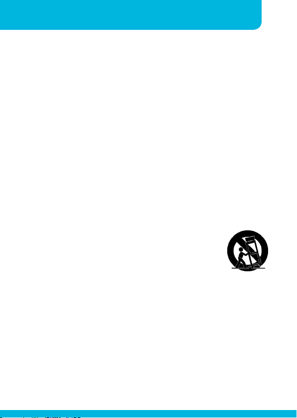
20. Use only with the cart, stand, tripod, bracket, or
table specified by the manufacturer, or sold with the
apparatus. When a cart or rack is used, use caution
when moving the cart/apparatus combination to avoid
injury from tip-over.
21. Refer all servicing to qualified personnel. Servicing is required when the
apparatus has been damaged in any way, such as power supply cord
or plug is damaged, liquid has been spilled or objects have fallen into
the apparatus has been exposed to rain or moisture, does not operate
normally, or has been dropped.
22. WARNING: To reduce the risk of fire or electric shock, do not expose this
apparatus to rain or moisture. The apparatus shall not be exposed to
dripping or splashing and that objects filled with liquids, such as vases,
shall not be placed on apparatus.
23. WARNING: The mains plug/appliance coupler is used as disconnect
device, the disconnect device shall remain readily operable.
5
Page 6
6
CLASS-D POWER AMPLIFIER
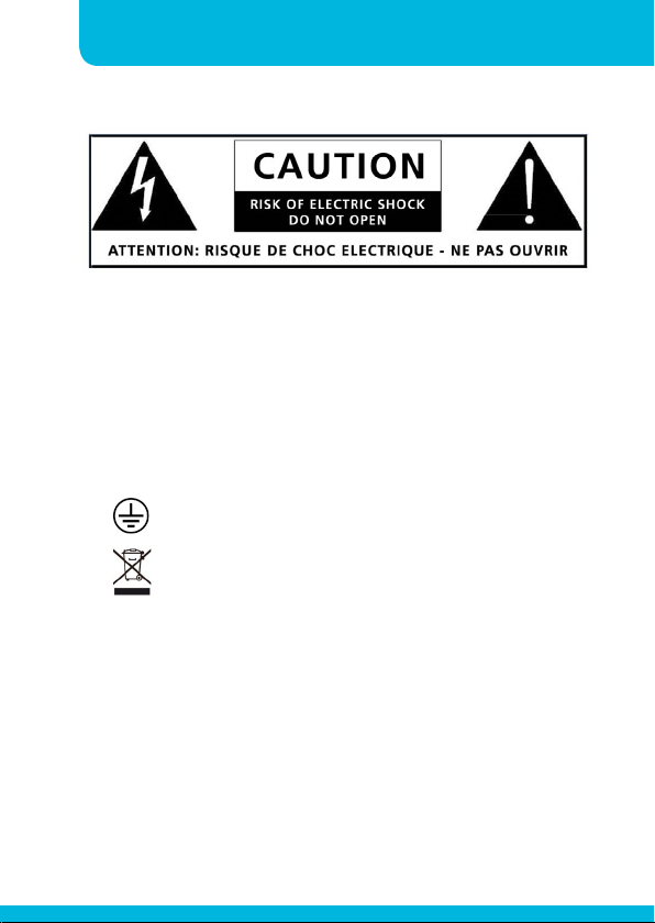
24. This lightning flash with arrowhead symbol within an equilateral triangle
is intended to alert the user to the presence of non-insulated “dangerous
voltage” within the product’s enclosure that may be of sufficient
magnitude to constitute a risk of electric shock.
- Warning: To reduce the risk of electric shock, do not remove cover (or
back) as there are no user-serviceable parts inside. Refer servicing to
qualified personnel.
- The exclamation point within an equilateral triangle is intended to
alert the user to the presence of important operating and maintenance
instructions in the literature accompanying the appliance.
25.
26.
27. No naked flame sources, such as lighted candles, should be placed on
28. Do not install this equipment in a confined or building-in space such
Protective earthing terminal. The apparatus should be connected
to a mains socket outlet with a protective earthing connection.
Correct Disposal of this product. This marking indicates that this
product should not be disposed with other household wastes
throughout the EU. To prevent possible harm to the environment
or human health from uncontrolled waste disposal, recycle it responsibly
to promote the sustainable reuse of material resources. To return your
used device, please use the return and collection systems or contact the
retailer where the product was purchased. They can take this product for
environmental safe recycling.
the apparatus.
as a book case or similar unit, and remain a well ventilation conditions
at open site. The ventilation should not be impeded by covering the
ventilation openings with items such as newspaper, table-cloths, curtains
etc.
Page 7

Instruction manualREVAMP2250
Features
• 1 rack unit high
• High power Hypex® class-D power amplifier modules
• Bridgeable 2 channel amplifier
• Dynamic output power: 2x350W @ 4Ω
• Sine wave power per channel: 2x250W @ 4Ω (500 msec)
• Dynamic bridged output power: 700W @ 8Ω
• Bridged Sine wave output power: 500 W @ 8Ω (500 msec)
• High thermal efficiency
• Highest possible damping factor
• Soft start switching power supply unit
• No cooling fan
• Low power consumption
• Integrated Analog Devices® digital signal processor (DSP) with easy
one button operation: simply push the button to select an operating
mode, making this amplifier the ideal multi purpose tool for your
applications
• LF filter for increased stability when using 100 volt transformers on
the output, allowing you to use 100 volt speakers as top speakers
combined with a standard low impedance subwoofer for example
• Integrated APC limiter/compressor
• Balanced euroblock inputs
• Unbalanced inputs on RCA with pass through
• Input level attenuators on all inputs
• 4-pole Speakon® speaker output connectors
• Euroblock speaker output connectors
• Extended speaker and amp protection circuits: DC protect, over
current protect, over temperature protect, input overload
• Individual channel mute buttons and versatile LED status indicators
• This unit has NOT been designed for use in mobile applications,
such as: mobile discobars, mobile PA systems, live bands, audio
rental systems, …
• Removable rack-ears
Note: the integrated APC limiter will automatically limit the incoming audio
signal to avoid overloads. This feature can not be defeated and acts as a
lifesaver for your valuable speakers.
7
Page 8
8
CLASS-D POWER AMPLIFIER
Connections
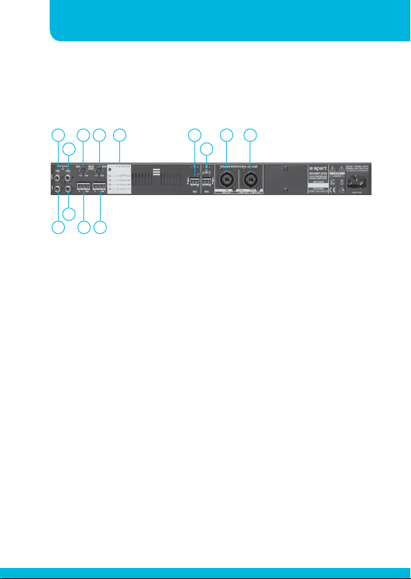
1
3 4 5 6 8 9
2 7
101112 13
1. Channel 2 overload led: when this led lights up, you are
overloading the input. Lower the input signal immediately to
prevent the amplifier from shutting down.
2. Channel 1 overload led: when this led lights up, you are
overloading the input. Lower the input signal immediately to
prevent the amplifier from shutting down.
3. Channel 2 input gain setting. Adjust the input gain to the
output level of your source. Make sure to avoid the clip led
lighting up at the strongest input peak level.
4. Channel 1 input gain setting. Adjust the input gain to the
output level of your source. Make sure to avoid the clip led
lighting up at the strongest input peak level.
5. DSP selector switch with led indicators: push the button to
scroll between the various pre-programmed DSP settings.
There are 6 possible DSP settings and 2 available combinations.
The settings will be memorized and recalled when the unit is
Page 9

Instruction manualREVAMP2250
powered up. Full details of the available settings can be found
below.
6. Channel 2 speaker output on 2 pole euroblock connector.
7. Channel 1 speaker output on 2 pole euroblock connector.
8. Channel 2 speaker output on speakon connector. Pin 1+ =
speaker 2 +, pin 1- = speaker 2 -.
9. Channel 1 and 2 stereo speaker output on speakon connector.
Pin 1+ = speaker 1 +, pin 1- = speaker 1 -; Pin 2+ = speaker 2+,
pin 2- = speaker 2-. In bridge mode, pin 1 + = speaker +, pin
2+ = speaker-.
10. Channel 2 unbalanced input and link cinch connector: connect
the line level input signal for channel 2 here. Line level is 0 dBV.
Input and link connector are internally connected 1 on 1.
11. Channel 1 unbalanced input and link cinch connector: connect
the line level input signal for channel 1 here. Line level is 0 dBV.
Input and link connector are internally connected 1 on 1. This
connector is also used in bridge mode or when DSP mode CH1
SUB – CH2 TOP is selected.
9
12. Channel 2 balanced input on 3 pole euroblock connector.
13. Channel 1 balanced input on 3 pole euroblock connector. This
connector is used in bridge mode or when DSP mode CH1 SUB
– CH2 TOP is selected.
14. Mains inlet: connect the mains power cord here.
Page 10
10
CLASS-D POWER AMPLIFIER
Operation
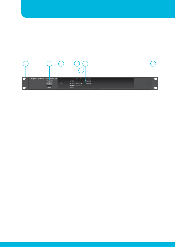
1 12 3 4 6
5
1. Removable rack ears for 19” rack mounting.
2. Power switch: after switching on the power, the power led will
light up after approx 1 second. The limit-muted leds will light
up for a few seconds to avoid excessive power on pop noise.
3. Power led
4. Channel 1 status led bar and mute switch: when the mute
switch is pressed, the orange “LIMIT – MUTED” led will light
up. This led will also light up when the internal limiter is
activated to avoid the amplifier from being overloaded by high
input signals. The “CLIP – OVERLOAD” led indicates that the
power amplifier is clipping: reduce the input signal at once
whenever this occurs !!! The green “SIGNAL - -40dB” led
will light up when an input signal is present. The red “INPUT
– OVERLOAD” indicates that the input is being overloaded.
Reduce the incoming signal at once !!!
5. Channel 2 status led bar and mute switch: when the mute
Page 11

Instruction manualREVAMP2250
switch is pressed, the orange “LIMIT – MUTED” led will light
up. This led will also light up when the internal limiter is
activated to avoid the amplifier from being overloaded by high
input signals. The “CLIP – OVERLOAD” led indicates that the
power amplifier is clipping: reduce the input signal at once
whenever this occurs !!! The green “SIGNAL - -40dB” led
will light up when an input signal is present. The red “INPUT
– OVERLOAD” indicates that the input is being overloaded.
Reduce the incoming signal at once !!!
6. DSP setting led display: the leds show which of the DSP settings
or combinations have been activated.
DSP features and audio signal routing:
There are 6 possible DSP settings and 2 available combinations.
The settings will be memorized and recalled when the unit is
powered up.
• CH1 SUB – TOP CH2: frequencies below 100 Hz are sent to the
sub channel (CH1). Frequencies above 100 Hz are sent to the
top channel (CH2).The Filter slope (12 dB/oct or second order
Butterworth characteristic) and frequency (100Hz) are fixed. The
Audio signal from input 1 is used.
• CH1 TRAFO LOAD: Use this mode when you want channel 1
of your amplifier to drive a transformer to drive 100V speaker
systems. This mode applies a highpass filter to channel 1. Filter
characteristics: 12 dB/oct at 50 Hz. Butterworth characteristic.
This setting increases amplifier stability when using a 100 volt
transformer on output 1.
• CH2 TRAFO LOAD: Use this mode when you want channel 2
11
Page 12

12
CLASS-D POWER AMPLIFIER
of your amplifier to drive a transformer to drive 100V speaker
systems. This mode applies a highpass filter to channel 2. Filter
characteristics: 12 dB/oct at 50 Hz. Butterworth characteristic.
This setting increases amplifier stability when using a 100 volt
transformer on output 1.
• CH1 BRIDGED CH2: both amps are used in bridge. Audio signal
from input 1 is used.
• Combination CH1 SUB – TOP CH2 with CH2 TRAFO LOAD: this
combination allows a low impedance subwoofer to be used
with 100 volt top speakers. Audio signal from input 1 is used.
This setting increases amplifier stability when using a 100 volt
transformer on output 2.
• CH1 TRAFO LOAD with CH2 TRAFO LOAD: a highpass filter is
applied to channel 1 and 2 to ensure that low frequencies are
filtered. Filter characteristics: 12 dB/oct at 50 Hz. Butterworth
characteristic. This setting increases amplifier stability when
using 100 volt transformers on the outputs.
Page 13

Instruction manualREVAMP2250
!!! IMPORTANT !!!
This amplifier relies on convectional cooling only. In normal
situations, overheating will not occur due to the class D amplifier
topology. Since there are no cooling fans in the amplifier, make
sure the convectional cooling system can work properly. The unit
can be built in a 19 inch rack system, but it is forbidden to block
the ventilation holes provided. Therefore, it is absolutely necessary
to allow at least one free rack space or 44 mm above and beneath
the amplifier. Make sure the ambient temperature is between 0
and 35°C. Operating the unit beyond its normal limits may cause
overheating. Power amplifiers are hard workers, and their behaviour
is similar to human beings. In extreme conditions, human beings are
not able to perform efficiently. This also applies to amplifiers. It is
generally a bad idea to mount multiple heat generating units such
as amplifiers in the same rack. If necessary, use a forced ventilation
system in your mounting rack.
The mains fuse is located inside the unit. When the fuse is broken,
replace it with a fuse of the same current and voltage rating: 5.0
AT/250V. For qualified personnel only!
This unit has NOT been designed for use in mobile applications,
such as: mobile discobars and DJ setups, mobile PA systems, live
bands, audio rental systems, …
13
Use it in fixed installations only.
Page 14
14
CLASS-D POWER AMPLIFIER
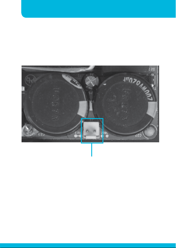
110 VAC operation: it is possible to operate the unit at 110 (115)
VAC.
Therefore, open the unit and set a wire jumper on the connector for
110 VAC operation.
Page 15
Instruction manualREVAMP2250
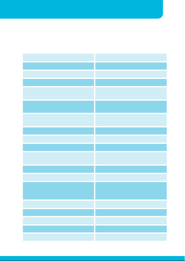
Technical specifications
dynamic output power 2 x 350 W @ 4 Ω
sine wave power per channel 250 W @ 4 Ω (500 ms)
dynamic output power bridged 700 W @ 8 Ω
sine wave power bridged 500 W @ 8 Ω
minimum output load impedance
CH1 and CH2
minimum output load impedance
bridge mode
input connections 2 x balanced euroblock, 4 x
input sensitivity 0 dBV / 1 V
input impedance 22 kΩ
S/N ratio >90 dB A weighted
THD ch. 1/2 <0.1% @ 100 W / 4 Ω / 1 kHz A
frequency response 10 – 24 kHz + 0 / - 3 dB
built-in DSP yes
protection circuits over current, over temperature,
channel separation >74 dB @ 1 kHz
damping factor > 50 all channels
APC sytem internal compressor and clip limiter
power amp topology class-D
power supply SMPS
4 Ω
8 Ω
unbalanced cinch with pass through
weighted
DC offset, AC and DC over- and
undervoltage
15
Page 16

16
CLASS-D POWER AMPLIFIER
cooling convectional
max power consumption 600 W
operating temperature range 0 to 35°C
power supply
dimensions 483 x 44 x 235 mm (including rack
net weight 3.1 kg
gross weight 4.9 kg
230 VAC / 50 Hz – 115 VAC / 60 Hz
(with internal jumper)
ears)
Page 17

Instruction manualREVAMP2250
17
Page 18
18
CLASS-D POWER AMPLIFIER
Page 19

Page 20

developed
by
Industriepark Brechtsebaan 8 bus 1
Audioprof nv
2900 Schoten - Belgium
Company names, product names and trademarks are property of their
Apart-Audio specifications are subject to change without notice.
respective owners.
 Loading...