

Page 1
D-ALINP
Instruction manual
Page 2

Page 3
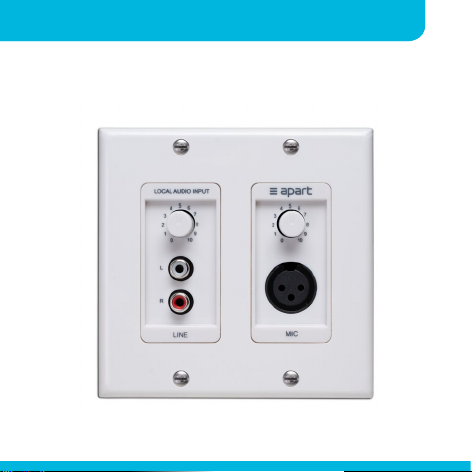
D-ALINP manual
Instruction manualD-ALINP
1
Page 4

2
LOCAL INPUT CONTROLS
Introduction
Please read this manual before using the product in
order to give you the necessary product and installation
instructions to assure a seamless installation and noncompromised overall sound quality and functionality.
Thanks for purchasing our D-ALINP Local Input Panel.
Affordable, versatile, but by no means a compromise
on functionality – Typically Apart!
Page 5

Instruction manualD-ALINP
Safety precautions
• Keep this manual for future reference.
• Take care of your connection wires, they should
be free of damage. Damaged wires may result in
poor performance or malfunctions and can cause
damage to installations.
• Only use accessories specified by the manufacturer
• No mains power shall be connected to the device,
doing so will damage the unit.
• This device should only be serviced by qualified
personnel. If not serviced by qualified personnel,
warranty may be void.
• Please check the packing for any kind of damage
upon receipt of the goods. If the packing is
3
Page 6

4
LOCAL INPUT CONTROLS
damaged, please contact your dealer before
opening it.
• Take notice that this unit must be protected from
moisture and is meant for indoor use only.
Features and benefits
• Inconspicuous and elegant design
• Fits in a standard 2 gang utility box
• Easy and foolproof 3-wire system
• Built in high quality input transformer to avoid
ground loops.
• Built in mic pre-amplifier.
• Phantom powered, no additional power supply
Page 7

Instruction manualD-ALINP
needed
• Line and microphone inputs
• Separate volume control for line and microphone
• Line and Microphone input are automatically mixed
together.
• Push lock volume buttons
• Exceptional audio quality
5
Page 8

6
LOCAL INPUT CONTROLS
Connecting and installing the unit
Please power off your master unit before connecting
the D-ALINP. It is possible to use standard low voltage
approved wires or cables such as standard CAT5 cables.
The D-ALINP will be hardwired to a balanced line input
of any suitable device with phantom power between
18V and 48V . The connection of the wires are
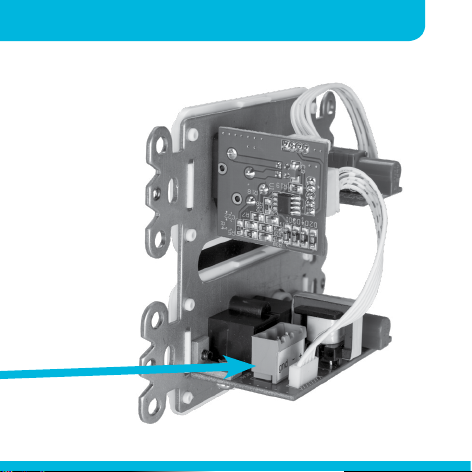
indicated on the D-ALINP. Please connect the wires to a
complementary device according to the labels.
Connect the wires here
Page 9
Instruction manualD-ALINP
7
Page 10
8
LOCAL INPUT CONTROLS
Do not connect more than one D-ALINP unit on the same
cable. This will cause malfunction and possible damage
to your main unit
and/or D-ALINP.
Avoid thick solid
wires, these will
cause mechanical
stress on the
connectors and
make installation
difficult.
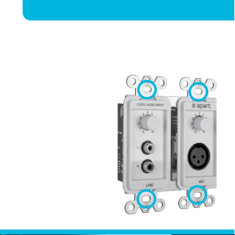
D-ALINP fits into
the standard
2 gang in-wall
utility boxes and
is connected with
4 6-32 thread
screws.
Page 11
Instruction manualD-ALINP
9
1
2
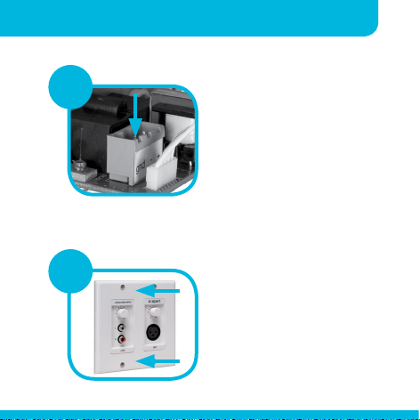
First, connect the wires
to the 3-pole MSTB
connector and install the
main electronic frame in
the in-wall box with the 4
provided screws.
After installation of the
electronic metal frame,
place and fasten the
faceplate with the 4
panel screws to finish the
installation.
Page 12

10
LOCAL INPUT CONTROLS
Using D-ALINP
To use the D-ALINP module please see that the
balanced input is configured as mono and that a
phantom voltage is present.
The D-ALINP sums the RCA-cinch inputs to mono. The
microphone and RCA-inputs have separate volume
control.
You will need to adjust the LINE input gain of your
host-device depending on your phantom voltage level
and depending on the source you will connect to the
ALINP panel.
As a rule of tumb: connect your source to the ALINP
panel, set the ALINP volume to 80% on the panel
and then adjust the input gain of your host to have
sufficient input (but not clipping) to your host device.
Page 13

Specifications
Instruction manualD-ALINP
11
Input sensitivity for nominal
output (0 dBV) RCA input
(@48 VDC phantom)
Input sensitivity for nominal
output (0 dBV) MIC input
(@48 VDC phantom)
Cable length Tested and full functional
SNR via de balanced mic
input
SNR via de unbalanced cinch noise floor -80 dBV, SNR
max THD at 1 kHz via de
balanced mic
max THD at 1 kHz via de
unbalanced cinch
-15 dBV, 177 mVrms
-33 dBV, 22.3 mVrms
with 600 m CAT6 cable
noise floor -80 dBV, SNR
86 dB
86 dB
0.05% at 1 kHz
0.05% at 1 kHz
Page 14

12
LOCAL INPUT CONTROLS
Rated input impedance
balanced MIC
Rated input impedance
unbalanced line
Dimensions (w x h x d) 116 x 115 x 50 mm
Cut-out dimensions 102 x 102 mm
Mounting depth minimally 45 mm
Connectors 3-pole MSTB connector
Fits in 2-gang utility wall box
Weight 173 g
Power supply 24 VDC, phantom powered
4 kohm
8.5 kohm
4.57 x 4.53 x 1.5 in
4.02 x 4.02 in
(5mm)
0.35 lb
by main unit
Page 15

Instruction manualD-ALINP
Note: The D-ALINP module was designed for use with
phantom voltages between 24 VDC and 48 VDC. The
specifications in the table above were measured at the
maximum phantom voltage of 48 VDC. Lowering this
phantom voltage to lead to a lower input range.
13
Page 16

developed
by
Apart Audio nv
Industriepark Brechtsebaan 8 bus 1
2900 Schoten - Belgium
Company names, product names and trademarks are property
Apart-Audio specifications are subject to change without notice.
of their respective owners.
 Loading...