

Page 1
CONCEPT1(T)
Instruction manual
Page 2

Page 3
CONCEPT1(T) Manual
Instruction manualCONCEPT1(T)
1
Page 4

2
Integrated amplifiers
Safety Instructions
• Please check the carton box for any kind of damage on
reception of the goods. In case of a damaged carton, please
contact your dealer before opening the carton.
• !!!! Danger !!!! Exposure to extremely high noise levels may
cause a permanent hearing loss. Individuals vary considerably to
noise induced hearing loss but nearly everyone will lose some
hearing if exposed to sufficiently intense noise for a sufficient
amount of time. Therefore it is recommended that all persons
exposed to equipment capable of producing high sound
pressure levels, such as this amplifier, be protected by hearing
protection while installing or operating this unit.
• Read all documentation before operating your equipment.
• Keep all documentation for future reference.
• Save the carton and packing material even if the equipment has
arrived in good condition.
• Should you ever need to ship the unit, use only the original
factory packing.
• Do not spill water or other liquids into or on the unit.
• Make sure power outlets conform to the power requirements
listed on the back of the unit.
• Do not use the unit if the electrical power cord is frayed or
broken.
• Have gain controls on amplifiers turned down during power-up
to prevent speaker damage if there are high signal levels at the
inputs.
Page 5

Instruction manualCONCEPT1(T)
• Do not connect the inputs / outputs of amplifiers or consoles
to any other Voltage source, such as a battery, mains source, or
power supply, regardless of whether the amplifier or console is
turned on or off.
• Power down & disconnect units from mains Voltage before
making connections.
• Do not use the unit near stoves, heat registers, radiators, or
other heat producing devices.
• Do not operate equipment on a surface or in an environment
which may distort the normal flow of air around the unit. If the
unit is used in an extremely dusty or smoky environment, the
unit should be periodically “blown free” of dust.
• Do not remove the cover. Removing the cover will expose you
to potentially dangerous Voltages.Do not drive the inputs with
a signal level higher than that required to drive equipment to
full output.
• Do not run the output of any amplifier back into another input.
• In case of mal-function this device should be serviced by
qualified service personnel only.
3
Page 6

4
Integrated amplifiers
Main features
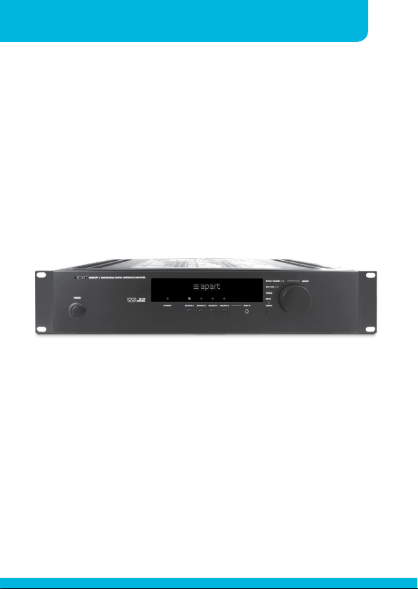
• 3 basic operating modes combined in 1 device: stereo, linked
mono and individual mono.
• Paging microphone input with 2 zone programmable paging
control.
• Standalone and/or RS232 controlled operation.
• Removable 19 inch rack ears.
• Menu driven hidden configuration accessible for installers only.
• Lockable front panel controls.
• Super simple no nonsense user interface.
• Multi functional stylish blue colour dot matrix VFD display.
• Presettable paging mic gain and separate tone control.
• Integrated switchable highpass filter for use with optional
subwoofers.
• Separate line out and pre out (fixed and variable line outs).
• 4 stereo gain adjustable line inputs with additional link out on
input 1.
• Line 4 input also available as a standard minijack in on the
frontpanel for connection of personal audio devices.
• Programmable maximum microphone and music levels for all
zones.
• Switchable automatic loudness compensation.
• 2 zone paging microphone optionally available.
Page 7

Instruction manualCONCEPT1(T)
• Low impedance (Concept 1) and 100 Volt speaker line outputs
(Concept 1T) available.
• Integrated limiter circuit.
• IR remote control optionally available.
• IR control extender optionally available.
• 2 x 60 watts freely assignable RMS output power at your
disposal.
5
Page 8
6
Integrated amplifiers
Front panel and display layout
9
10
11
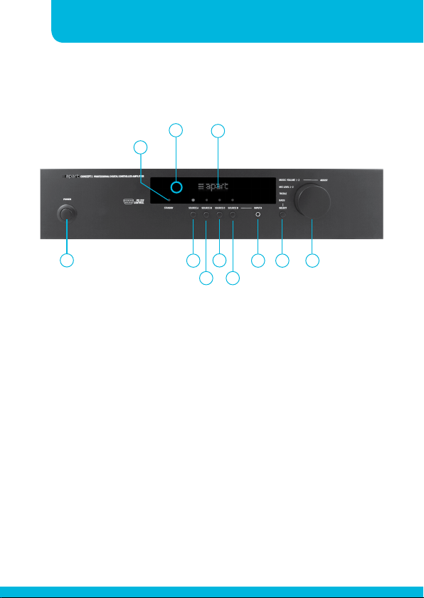
1
1. Power on/off button: push this button to turn the power on
and off
2. Source A selector: push this button to select line source A
3. Source B selector: push this button to select line source B
4. Source C selector: push this button to select line source C
5. Source D selector: push this button to select line source D
6. Source D minijack input: this line input is shared with the source
D connector at the rear
7. Select button: push this button to select basic submenus
8. Multifunctional encoder knob: turn this knob to adjust the main
volume and other menu parameters
2
6 7 8
345
Page 9
Instruction manualCONCEPT1(T)
9. Stand-by led: this led is lit when the unit is powered off by
RS232 control
10. Infrared receiver
11. Multi functional dot matrix VFD display
Rear panel layout
7
1 2 3
6
4
5
8
7 9
10
13
12
11
15
14
16
17
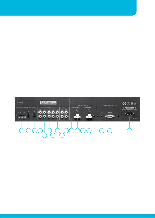
1. Microphone input: connect your (paging) microphone on this
euroblock connector, connect the signal on +, -, the screen on
GND. Connect the eventual paging contacts between GND and
Z1 (for zone 1) and between GND and/or Z2 (for zone 2). The
input gain can be adjusted with knob 2 between line and mic
level to avoid distortion.
2. Mic input gain control: mic input gain adjust
3. Mic input tone control: adjust the tone of the mic input
between dark and bright
Page 10

8
Integrated amplifiers
4. Link output: the signal here is a copy of the line A input signal
5. Line A: stereo line RCA connector
6. Line B: stereo line RCA connector
7. Line C: stereo line RCA connector
8. Line D: stereo line RCA connector, a mini jack version of the line
D input is available on the front panel. Only use one of the two
input’s at the same time.
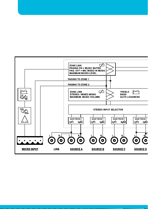
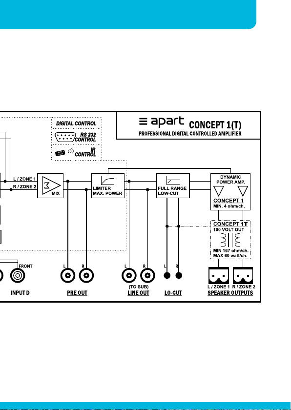
9. Pre-amp out: these RCA connectors offer a line level signal,
after the master volume, but before the limiter. For details,
please take a look at the block diagram on page 7.
10. Line out: these RCA connectors carry the line level signal after
passing the volume control and limiter circuit. This is an ideal
way to connect to active subwoofers or extra power amplifiers
11. Lo-cut right channel/zone 2: when this button is pushed, the
signal to the internal power amplifier reduces the sub bass
frequencies for driving small sized top speakers. It works ideally
in combination with subwoofers
12. Right channel/zone 2 output: use this euroblock connector to
connect your right/zone 2 speaker, minimum load impedance is
4 Ohm (167 Ohm for T version)
13. Lo-cut left channel/zone 1: when this button is pushed, the
signal to the internal power amplifier reduces the sub bass
frequencies for driving small sized top speakers. It works ideally
in combination with subwoofers
14. Left channel/zone 1 output: use this euroblock connector to
connect your left/zone 1 speaker, minimum load impedance is 4
Page 11

Instruction manualCONCEPT1(T)
Ohm (167 Ohm for T version)
15. IR jack: connect the optionally available IR remote receiver
on this minijack connector: Sleeve =GND, ring = data, tip =
+5VDC. Once this receiver is connected, the IR-receiver behind
the front panel is bypassed.
16. RS232: 9 pin sub D connector for connection of computers or
other automated audio system controllers
17. Ac input: plug in the supplied mains cable here. Check your
mains Voltage first !
9
Page 12
10
Integrated amplifiers
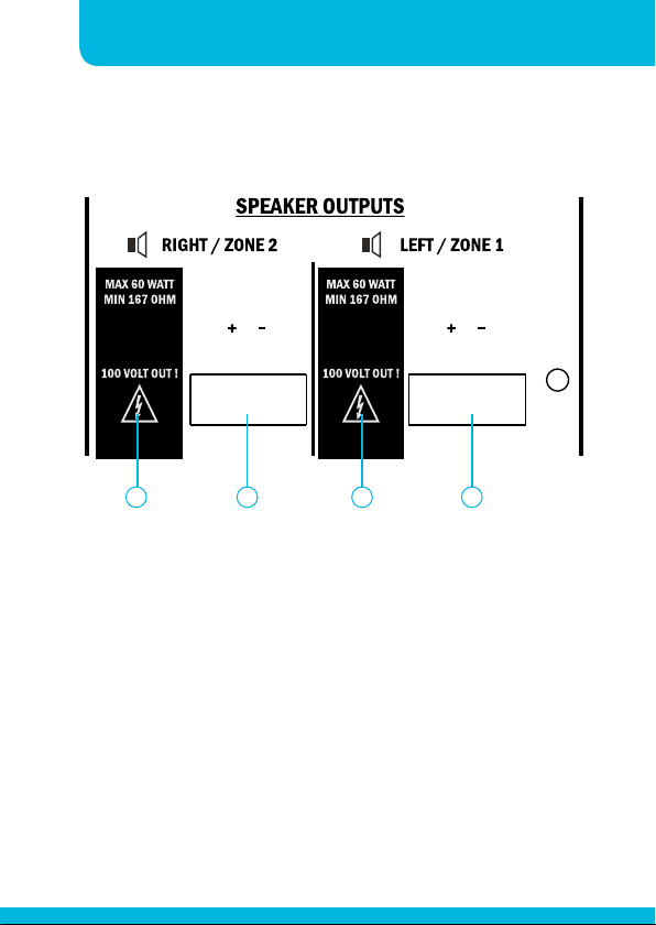
CONCEPT1T Version
Difference on Concept 1T
21 3 4
1. lo-cut Right channel/zone 2: switch not available
2. Right channel/zone 2 output on euroblock connector: minimum
load impedance: 167 Ohm or 60 watts/100 Volt
3. lo-cut Left channel/zone 1: switch not available
4. Left channel/zone 1 output on euroblock connector: minimum
load impedance: 167 Ohm or 60 watts/100 Volt
Page 13

Instruction manualCONCEPT1(T)
User Operation
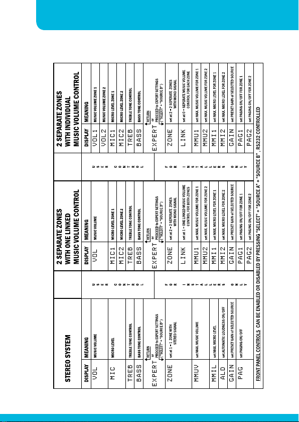
The table below shows the 3 possible operating modes: stereo, 2
separate mono zones with one linked music volume control and
2 separate mono zones with individual music volume control. You
can adjust the volume by turning the large rotary control from -80
dB (lowest) to 0 dB (highest). Volume adjustment is the default
parameter assigned to the rotary control. In order to enter the
menu, press the select button next to the large rotary control.
Example in stereo operating mode: press the select button once to
show the first editable parameter, VOL appears in the display.
Push the select button a second time to adjust the microphone
level, MIC appears in the display.
Push the select button a third time to adjust treble tone control,
TREB appears in the display.
Push the select button a fourth time to adjust bass tone control,
BASS appears in the display.
Push the select button again, EXPERT appears in the display. This
menu is not allowed for the user. Push the select button again to
return to VOL or wait a few seconds, the display will jump back to
VOL automatically.
11
Page 14
12
Integrated amplifiers
Page 15

Instruction manualCONCEPT1(T)
Expert Operation
In order to edit the EXPERT parameters, push select repeatedly until “EXPERT” appears
in the display. Then press the ‘SELECT’ and the ‘SOURCE D’ button. A hidden menu
structure is now available and gives you the opportunity to edit several parameters, such
as operating mode, maximum music level and so on. The table shows the entire menu
structure. The menu tree is also printed on top of the Concepct1 unit and should need no
further explanation. To leave the EXPERT mode: press ‘SELECT’ and the ‘SOURCE’ button
simultaniously. In the EXPERT mode if there is no action for 1 minute, the unit will auto
return to USER mode.
RS232 & IR Information
Please check our website for the latest information on RS232 and IR communication:
Concept1 RS232 Manual
Concept1 IR Manual
13
Page 16
14
Blockdiagram
Integrated amplifiers
Page 17
Instruction manualCONCEPT1(T)
15
Page 18
16
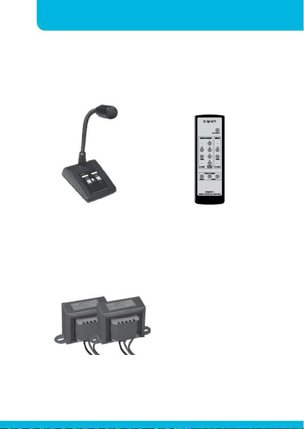
Accessories
Integrated amplifiers
MICPAT-2
CONCEPT1T-KIT
Kit of 2 pcs 100V transformers
to change 1 or 2 channels of
the CONCEPT1 into 100 Volt
line outputs.
CONCEPT1-RC
Infrared remotecontrol unit.2-zone paging microphone.
Page 19

Instruction manualCONCEPT1(T)
ERROR conditions
Symptom Display Solution
No power No display Replace main fuse. The fuse
No power, unit is
very hot
No sound Amp error Switch power off and on again, if
Overheated Hightemp Wait for cool down, reduce volume
Only for concept1t
version
No display Power off the unit, wait for cool
is located inside the unit near
the power switch. For qualified
personnel only.
down and power on again.
error is not solved, check amp fuses
on main pcb and replace if necess
ary. For qualified personnel only.
and check speaker loads.
17
No sound Amp error Check if the environment
temerature is within the operating
range of the unit (0° - 40°C).
If any of these fault conditions occur, please unplug the power cord
first, check your speaker lines, remove overloads.
Page 20
18
Integrated amplifiers
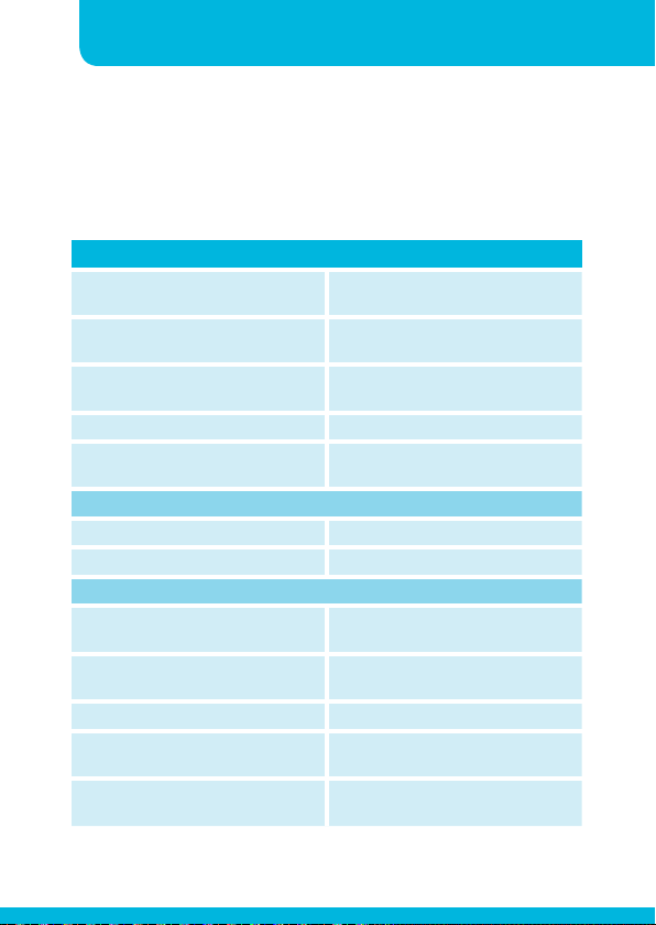
Technical Specifications
CONCEPT 1
dynamics program power, both
channels driven, 8 ohm
dynamics program power, both
channels driven, 4 ohm
note Power output controlled by digital
Lo-cut filter 75 Hz / 12 dB / oct
Loudspeaker impedance connection
Digital control
RS232 SUB-D9, galvanically isolated
IR (IR-remote control optional) Front ir eye, rear mini-jack
Inputs / outputs
source inputs A-B-C-D input
impedance / sensitivity
source inputs A-B-C-D digital preset
gain range
source digital tone control bass 90 Hz, treble 15 kHz, +/- 14 dB
automatic loudness +6 dB (90 Hz) / +4 dB (15 kHz) to
micro balanced input impedance /
sensitivity
2 x 60 watts
2 x 80 watts
limiter
4 - 16 ohms / channel
euroblock secured screw terminals
15 kohm / 0.3 V -10 dBV,
max 2.7 V +8.5 dBV
-20 / +14 dB
flat 0 dB
1.5 kohm / 1.5 MV -56 dBV,
max 0.4 V -8 dBV
Page 21
Instruction manualCONCEPT1(T)
19
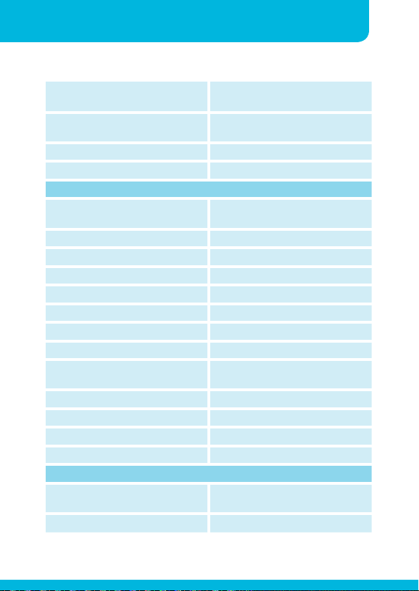
micro balanced input rear panel
gain trim
micro tone control; rear panel
LO - HI
pre-out impedance / sensitivity 1 kohm / 0 dBV
line-out impedance / sensitivity 1 kohm / +3 dBV
general
operation modes stereo / 2 zones linked / 2 individual
micro paging 1 or 2 zone
frequency response (- 0.5 dB) 10 Hz - 40 kHz
THD < 0.05 %
IMD < 0.09 %
noise a-weighted > 100 dBA
gain 33 dB
damping factor > 100
protection systems DC, temp, clip, overcurrent, short-
cooling convection, no fan
power consumption max 170 watts
mains power requirements 240 - 230 VAC, 50 - 60 Hz
temperature operating range 0° - 40°C
physical specifications
net dimensions (w x h x d) mm 430 (without rackears) x 88 x 290
gross dimensions (w x h x d) mm 530 x 380 x 170
-56 / -16 dBV mic - line
100 Hz / +3 dB, 10 kHz / -6 dB to
100 Hz / -9 dB, 10 kHz / +4dB
zones
circuit
(320 including knobs)
Page 22
20
Integrated amplifiers
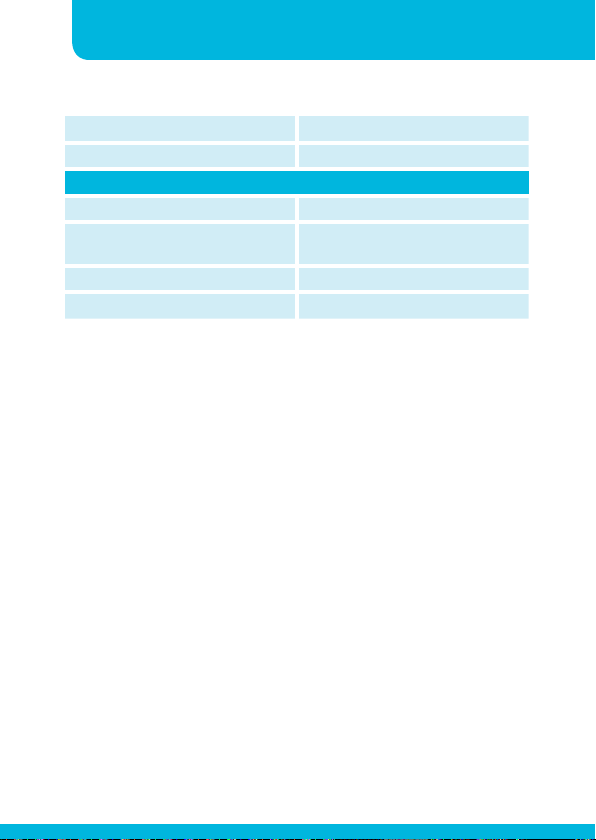
net weight 6.6 kg
gross weight 7.6 kg
CONCEPT 1T (100 volt output version)
all specs same as above, except;
rms program power, both channels
driven, 167 ohm / CH,
net weight 8.2 kg
gross weight 9.2 kg
60 W / 100 volt + 60 W / 100 volt
Page 23

21
Page 24

developed
by
Industriepark Brechtsebaan 8 bus 1
Audioprof nv
2900 Schoten - Belgium
Company names, product names and trademarks are property of their
Apart-Audio specifications are subject to change without notice.
respective owners.
 Loading...