

Page 1
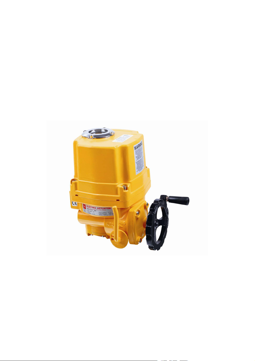
AOX-Q ELECTRIC ACTUATOR
The Instruction Book
Page 2

- 1 -
1. General Safety Instructions
2. Summary
3. Performance Features
4. Primary Technical Parameter
5. Structure
6. General Drawing
7. Wiring Diagram
8. Installation of Electric Actuators
9. Debug Description
10. Running Test
11. Maintenance
Page 3
- 2 -
1. General Safety Instructions
Do not open the upper shell when with main power
Check the specification on the nameplate is the same as order specification.
Pls reading the instruction book before using
Pls reset the limit switches when mounting the valve
Do not change the internal wiring
If the power supply is 3 phase, should to check the rotating direction.
2. Summary
"AOX-Q" series electric actuator is used for controlling 0° ~ 270° rotation of the valves and other similar
products, such as butterfly valve, ball valve, damper, flapper valve, cock valve etc. It widely applies to petroleum,
chemical, water treatment, shipping, paper making, power plant, heating, light industry and other industries.
Drived by 380V/220V/110VAC power or 24V/110VDC power, inputs 4-20mA or 0-10VDC control signal,
moves valve to the right position, and achieves to automatic control, maximum output torque is 6000N·M.
3. Performance Features
3. 1. Shell--The shell is made of aluminum alloy, with anodic oxidation treatment and polyester powder coating.
It is strong corrosion-resistant and enclosure IP67,NEMA 4 and 6, IP68 and explosion-proof is optional.
Page 4

- 3 -
3.2. Motor--Asynchronous motor, small, large torque, and small inertia force, F-class insulation rating, with
thermal protection to avoid damaging.
3.3. Manual Structure--The design of handwheel is safe, reliable, labor-saving, small. Declutch to operate by
handwheel if without power, and reset automatically when power on.
3.4. Indicator-- Installs indicator in the center axis and adopts convex mirror design, no cumulate water, more
convenient to observe.
3.5. Space heater-- It is used for controlling temperature to avoid condensing internal of housing and keep dry.
3.6. Limit switch--Mechanical, electronic double limit. Mechanical limit stopper is adjustable, safe and reliable;
electronic limit switch is controlled by cam. Set position accurately and conveniently, and not affected by
excessive handle.
3.7.Torque Switch-- (Except AOX-Q-005/008/010) Providing overload protection to avoid the damage of valve
and electric actuator when jammed by cutting power automatically.
3.8.Self-locking--Accurate worm and worm gear transfer large torque efficiently , high efficiency, low noise
(max. 50 dB), long life, with self-locking, prevent inversion, as stable and reliable transmission parts, no need to
refuel.
3.9. Anti-off bolt—The bolt attaches to the shell and be not off when remove the shell.
3.10.Installation--The installation size meets international standard ISO5211 / DIN3337.
3.11. Circuit--Controlling circuit meets the single-phase or three-phase power supply standard, circuit layout is
reasonable and compact, terminals meet various of additional functional requirements effectively.
3.12 The display of valve position—During the opening or closing movement of actuator, the change of valve
position on LCD is displayed with large numbers.
3.13 Adjust the phase sequence automatically—Intelligent actuator check and test the phase sequence for 3 phase
power supply automatically, users no need to consider about the phase sequence.
Page 5

- 4 -
4. Primary Technical Parameter
Model
Max
Output
Torque
60/50Hz
Operating
Time
Max
Drive
Shaft
Size
Power
Rated Current(A
)
Hand
wheel
Revolution
Weight
single phase
three phases
N·M
90°mmW
110V
220V
380V
440V
N
Kg
AOX-Q-005
50
18/22
Φ20201.10/0.95
0.55/0.54
0.3/0.3
N/A107.5
AOX-Q-008
80
18/22
Φ20201.10/0.95
0.55/0.54
0.3/0.3
N/A107.5
AOX-Q-010
100
18/22
Φ20201.10/0.95
0.55/0.54
0.3/0.3
N/A107.5
AOX-Q-015
150
21/25
Φ22401.65/1.67
0.88/0.84
0.31/0.31
0.30/0.31
11
17.3
AOX-Q-020
200
21/25
Φ22401.67/1.67
0.89/0.85
0.31/0.31
0.30/0.31
11
17.3
AOX-Q-030
300
26/31
Φ35901.85/1.86
0.92/0.92
0.35/0.35
0.34/0.34
13.5
22
AOX-Q-050
500
26/31
Φ35903.60/3.62
1.55/1.58
0.59/0.59
0.58/0.58
13.5
23
AOX-Q-060
600
26/31
Φ35
120
3.65/3.62
1.60/2.20
0.60/0.59
0.59/0.58
13.5
23
AOX-Q-080
800
31/37
Φ45
180
4.10/4.10
2.15/2.20
0.85/0.85
0.79/0.79
16.5
29
AOX-Q-120
1200
31/37
Φ45
180
4.20/4.10
2.35/2.30
0.87/0.87
0.81/0.81
16.5
29
AOX-Q-150
1500
78/93
Φ45
120
3.65/3.62
1.60/2.20
0.60/0.59
0.59/0.58
40.5
77
AOX-Q-200
2000
93/112
Φ45
180
4.10/4.10
2.15/2.20
0.85/0.85
0.79/0.79
49.5
83
AOX-Q-300
3000
93/112
Φ45
180
4.20/4.10
2.35/2.30
0.87/0.87
0.81/0.81
49.5
83
AOX-Q-400
4000
155/185
Φ45
180
4.20/4.10
2.35/2.30
0.87/0.87
0.81/0.81
82.5
83
AOX-Q-500
5000
155/185
Φ45
180
4.20/4.10
2.35/2.30
0.87/0.87
0.81/0.81
82.5
83
AOX-Q-600
6000
155/185
Φ45
180
4.20/4.10
2.35/2.30
0.87/0.87
0.81/0.81
82.5
83
4.1 AOX-Q series electric actuator technical parameter
Page 6
- 5 -
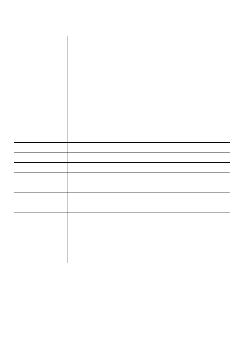
4.2 Standard Technical Parameter
Shell
Enclosure :IP67,NEMA4, Exd II CT5
Power
Standard:220VAC/1ph
Optional:110VAC/1ph, 380V/440V/3ph,50/60Hz, ±10%
24VDC/110VDC/220VDC
Motor
Asynchronous motor
Limit switch
2×Open/ Close, SPDT,250VAC 10A
Auxiliary limit switch
2×Open/ Close, SPDT,250VAC 10A
Torque switch
Close/Open, each 1, SPDT,250VAC 10A
Except AOX-Q-005/008/010
Travel
90°±10°
0°~270°
Fail safe/
Operating temperature
Internal-placed thermal protection, Open 115℃±5℃/Close 97℃± 5
℃
Indicator
Continuous position indicator
Manual operate
Declutching mechanism, operate by handwheel
Self-locking device
Self-locking by worm and worm gear
Mechanical limit
2 × external adjustable stopper
Space heater
30W(110V/220VAC)
Conduit entry
2 × PF 3/4”
Ambient temperature
-20℃~+70℃
Lubrication
Grease moly(EP type)
Material
Steel, Aluminum alloy, Aluminum bronze,Polycarbonate
Ambient humidity
Max 90%RH
Non-Condensing
Anti-vibration
X Y Z 10g,0.2~34 Hz,30 minutes
External coating
Dry powder, Epoxy polyester,high anti-corrosion
Page 7

- 6 -
4.3 Option Specification
No.
Option scheme
Remark
1
Explosion-proof actuator(Exd ⅡCT5)
AOX-Q series
2
Water-proof actuator (IP68,10M,250HR)
AOX-Q series
3
Potentiometer unit(1K-10K
)
AOX-Q series
4
Proportion control unit (control signal 4-20mA DC/1-5V/1-10V)
AOX-Q series
5
Local control units (local control open/stop/close optional switch, local/remote
switch)
AOX-Q series
6
Travel 120°, 180°,270°
AOX-Q series
7
Direct current motor (24VDC)
AOX-Q series
8
Torque switch (SPDT× 2 250VAC 10A)
Except
AOX-Q-005/008/010
9
Electric current position sensor (output 4-20mA DC)
AOX-Q series
10
Self-reset when power failure
AOX-Q series
11
High temperature resistance actuator (-10℃~+100℃)
AOX-Q series
12
Low temperature resistance actuator (-40℃~+70℃)
AOX-Q series
13
Low speed actuator
AOX-Q series
5.Structure
Electric actuators is make up of the following parts
◎ Housing: including shell and base
◎ Drive parts: asynchronous motor
◎ Driving mechanism:double worm and clutch
◎ Ratio control parts:separate with the mechanical parts, easy to debug
◎ Torque switch and limit switch parts
◎ Opening detected and feedback parts.
Page 8
- 7 -
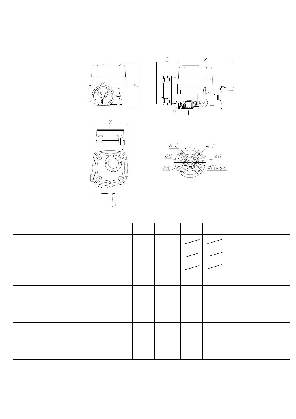
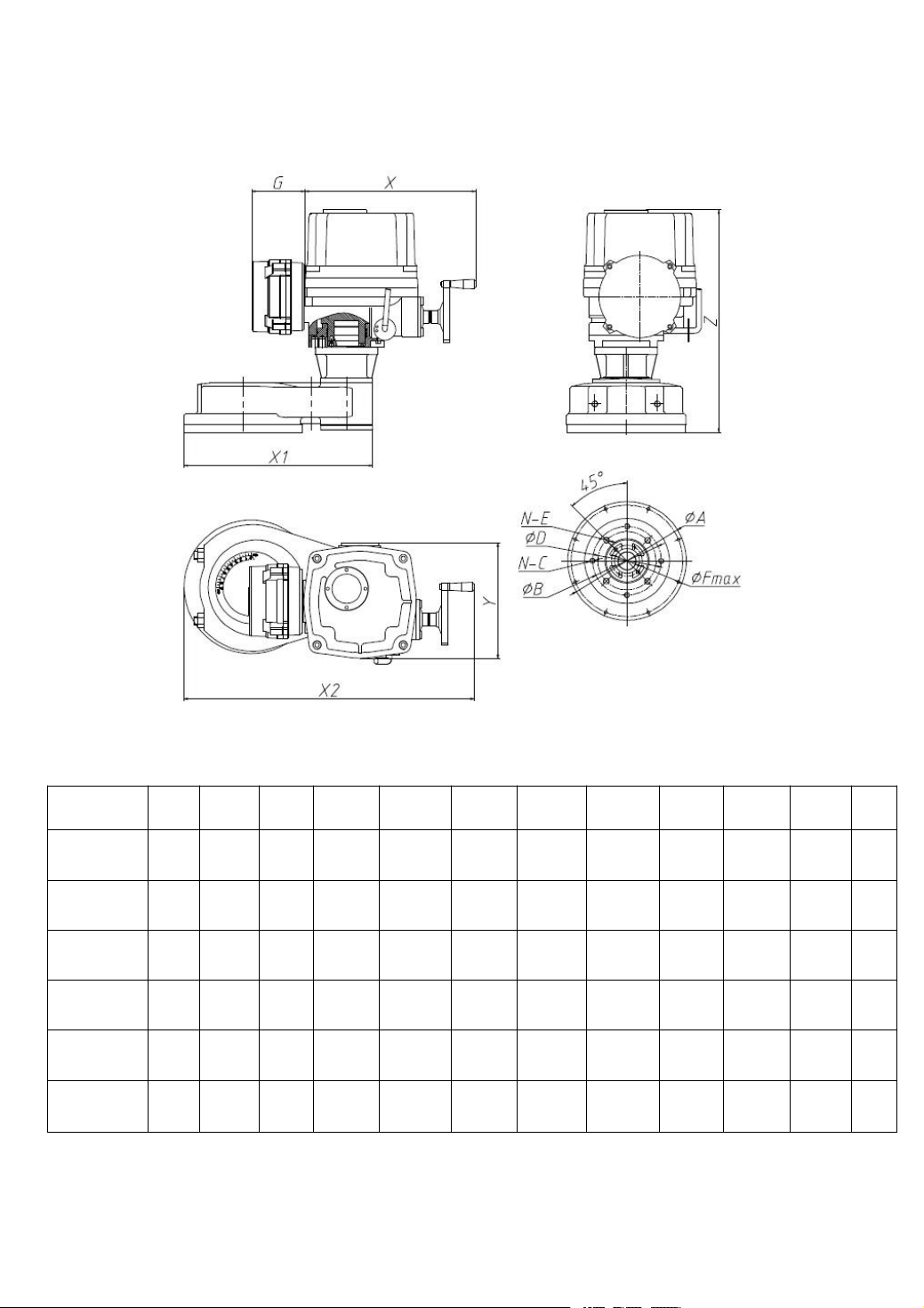
6. General Drawing
Model
XYZΦAΦB
N-CΦDN-EΦFG
H
AOX-Q-005
260
161
236
Φ90
Φ70
4-M8Φ20
140
40
AOX-Q-008
260
161
236
Φ90
Φ70
4-M8
Φ20
140
40
AOX-Q-010
260
161
236
Φ90
Φ70
4-M8
Φ20
140
40
AOX-Q-015
351
227
270
Φ125
Φ102
4-M10
Φ70
4-M8
Φ22
140
45
AOX-Q-020
351
227
270
Φ125
Φ102
4-M10
Φ70
4-M8
Φ22
140
45
AOX-Q-030
367
242
290
Φ150
Φ125
4-M12
Φ102
4-M10Φ35
140
55
AOX-Q-050
367
242
290
Φ150
Φ125
4-M12
Φ102
4-M10
Φ35
140
55
AOX-Q-060
367
242
290
Φ150
Φ125
4-M12
Φ102
4-M10
Φ35
140
55
AOX-Q-080
410
276
330
Φ180
Φ140
4-M16
Φ140
4-M12
Φ45
140
65
AOX-Q-120
410
276
330
Φ180
Φ140
4-M16
Φ140
4-M12
Φ45
140
65
6.1 AOX-Q-005~120 Appearance and installation dimension
Picture 1 Unit: mm
Page 9
- 8 -
6.1 AOX-Q-150~600 Appearance and installation dimension
Model
XYZ
ΦA
Φ
B
N-
C
Φ
D
N-EΦFGX1
X2
AOX-Q-150
410
276
330
Φ285
Φ165
4-M18
Φ140
4-M16Φ45
140
454
696
AOX-Q-200
410
276
330
Φ285
Φ165
4-M18
Φ140
4-M16Φ45
140
454
696
AOX-Q-300
410
276
330
Φ285
Φ165
4-M18
Φ140
4-M16
Φ45
140
454
696
AOX-Q-400
410
276
330
Φ285
Φ165
4-M18
Φ140
4-M16
Φ45
140
454
696
AOX-Q-500
410
276
330
Φ285
Φ165
4-M18
Φ140
4-M16
Φ45
140
454
696
AOX-Q-600
410
276
330
Φ285
Φ165
4-M18
Φ140
4-M16
Φ45
140
454
696
Picture 2
Unit:mm
Page 10
- 9 -
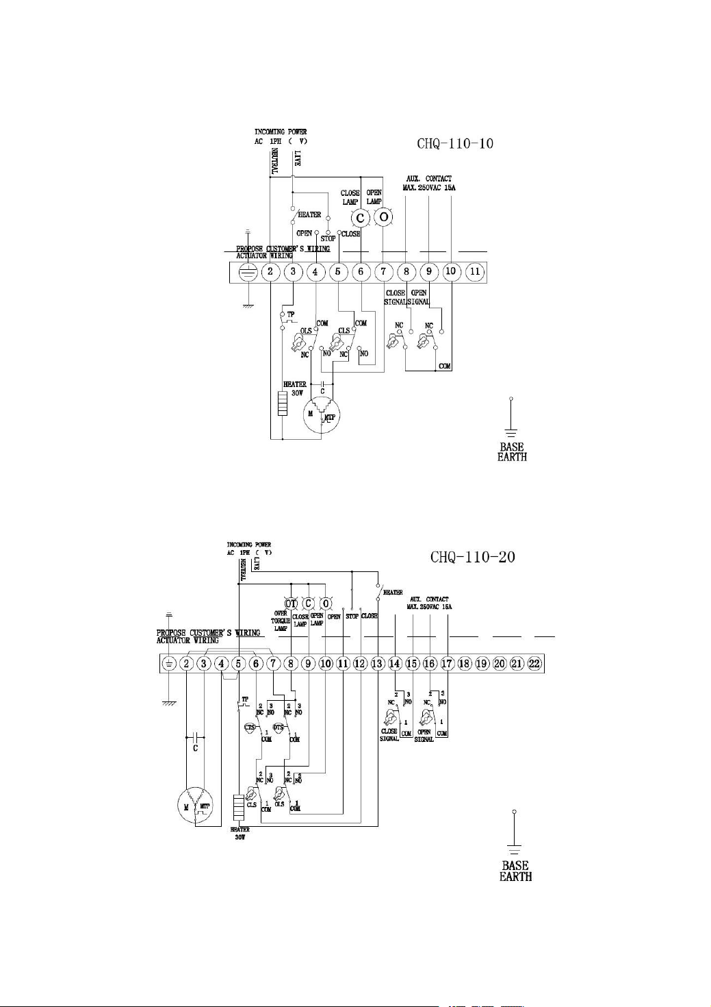
7. Wiring Diagram
7.1 AOX-Q-005~010 110/220VAC/50/60Hz,1Ph(on/off model)
Picture 3
7.2 AOX-Q-015~600 110/220VAC/50/60Hz,1Ph(on/off model
)
Picture 4
Page 11
- 10 -
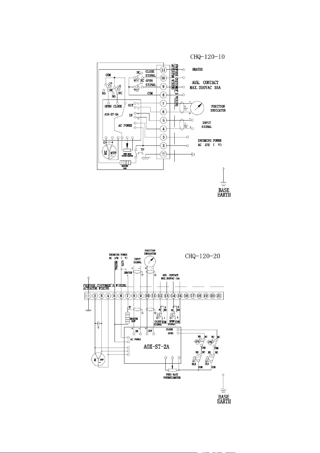
7.3 AOX-Q-005~010 110/220VAC/50/60Hz,1Ph (modulating model)
Picture 5
7.4 AOX-Q-015~600 110/220VAC/50/60Hz,1Ph (Standard modulating model)
Picture 6
Page 12
- 11 -
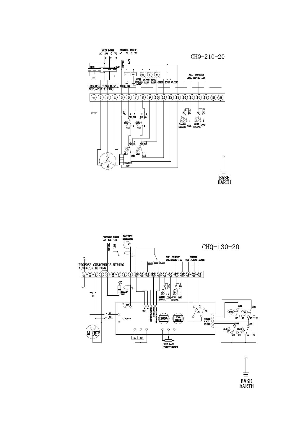
7.5 AOX-Q-015~600 380V/440V AC/50/60Hz,3Ph (External standard on/off model)
Picture 7
7.6 AOX-Q-015~600 110/220VAC/50/60Hz,1Ph (Intelligent on/off model)
Picture 8
Page 13
- 12 -
8、Installation of Electric Actuators
8.2 Mounting with Valve
8.2.1Turn valve by hand and check the situation, then turn to full-closed position
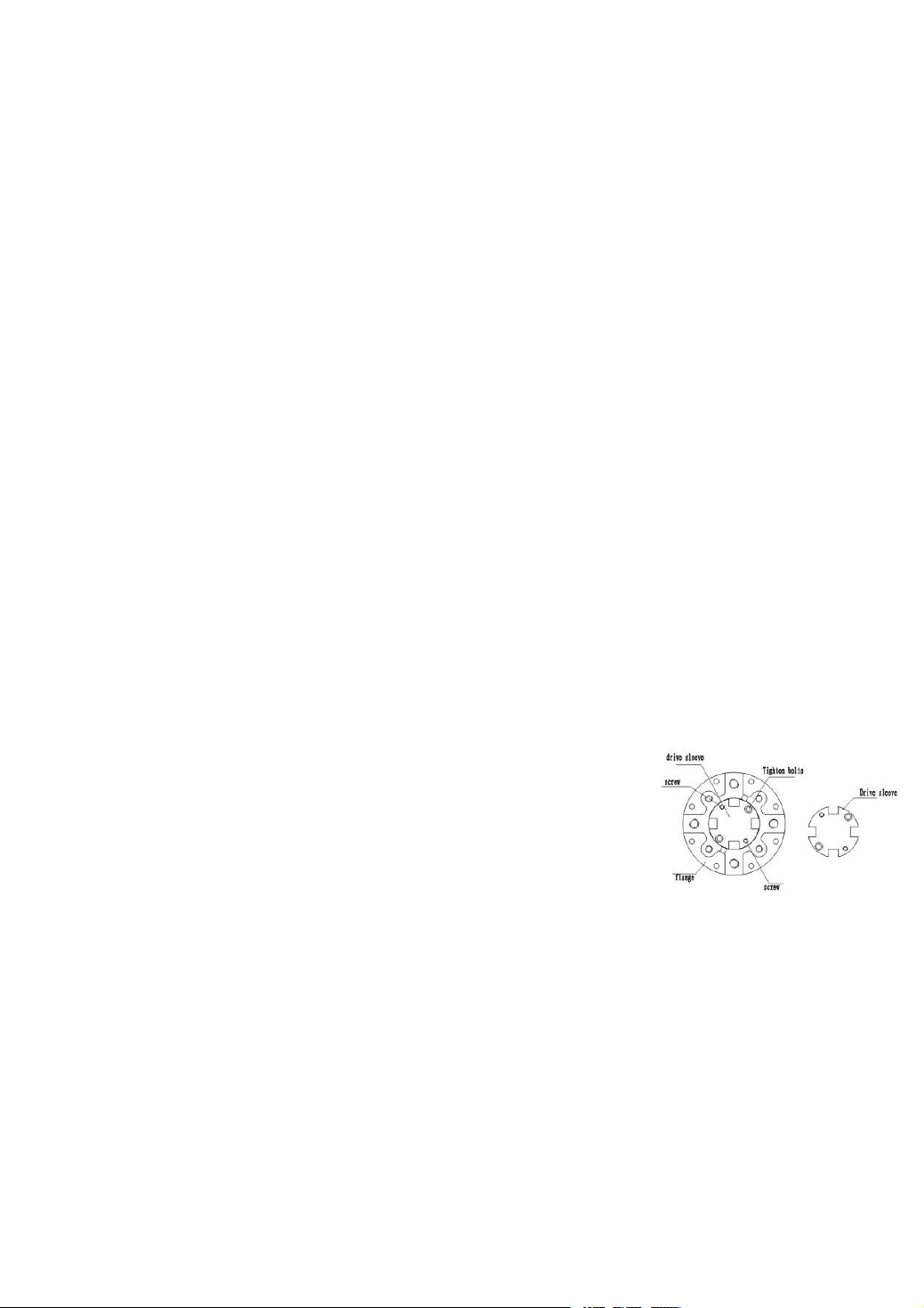
8.2.2 The drive shaft is removable and solid before leaving factory (picture 9)
(Note:the size of drive shaft can be machined according to user’s requirement in
square or round)
8.2.3 Before mounting,attention to keep correspondence with the rotate direction
between electric actuator and valve
8.2.4 Fix the bracket on valve
8.1 Installation Sites
8.1.1 Notes for interior installation
◎Pls don’t install non-explosion-proof product to the place with explosive gas
◎When installing in the submerged or outdoor, please inform to us in advance
◎Please reserve space for cable repairing , manual operation.
8.1.2 Notes for outdoor installation
In order to avoid rain, direct sunlight and so on, a protective cover or enclosure IP68 is available
◎
Please reserve space for cable repairing , manual operation.
◎
8.1.3 Ambient temperature
◎Ambient temperature at -30℃~+60℃;
◎When Ambient temperature is below zero, need to install space heater.
8.1.4 Fluid temperature
When equipped with valve, the heat of the fluid will transfer to the body, then the body temperature will rise.
◎Standard bracket: when the fluid temperature is below +65℃, with standard bracket or without bracket;
◎ Intermediate temperate bracket: when the fluid temperature is over +65 ℃ , with intermediate temperate
bracket;
◎High-temperature bracket:when the fluid temperature is over +180℃, with high-temperature bracket.
8.2.5Turn electric actuator to full-closed position, fix valve stem and electric actuator drive shaft
Picture 9
by coupling and screws.
8.2.6 Put the electric actuator on bracket, and screw lightly
8.2.7Turn valve by manual to full-closed position and confirm at right situation .
8.2.8Turn electric actuator by manual to confirm non-eccentric, smooth movement, and attention no over travel!
Note: Decrease hysteresis of the coupling as far as possible.
Page 14
- 13 -
8.3 Wire for Power
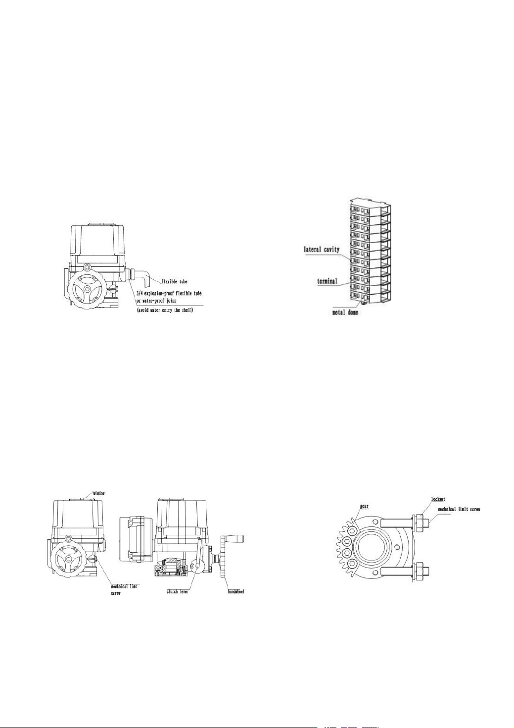
8.3.1 Remove the metallic plug and insert cables, pls use 3/4” explosion-proof joint in male thread or
explosion-proof flexible tube.
8.3.2 If the joint is mismatch to the actuator, will result in destroying the sealing that can not meet the enclosure
requirement.
8.3.3 Adopt water-proof arrangement when use wire pipe.
8.3.4 Take off shell cover,Press down the metallic dome in the hole of terminal by screwdriver, meanwhile, insert
the leadwire to lateral cavity. And then remove screwdriver.
Picture10 Picture 11
9. Debug Description
9.1 Adjustment of Mechanical Limit
Loosen the mechanical limit stoppers and locknuts, turn handwheel one circle, one side move the clutch
handle in left until occlude, continue to turn the handwheel until the actuator move to the full-close position. Turn
nuts until touch the fan-shaped gear, then turn two circles in anticlockwise direction, tight the locknuts at lastly. It
is the way to set the full-closed position of actuator , the same way to set full-open position.
Picture 12 Picture 13
Page 15
- 14 -
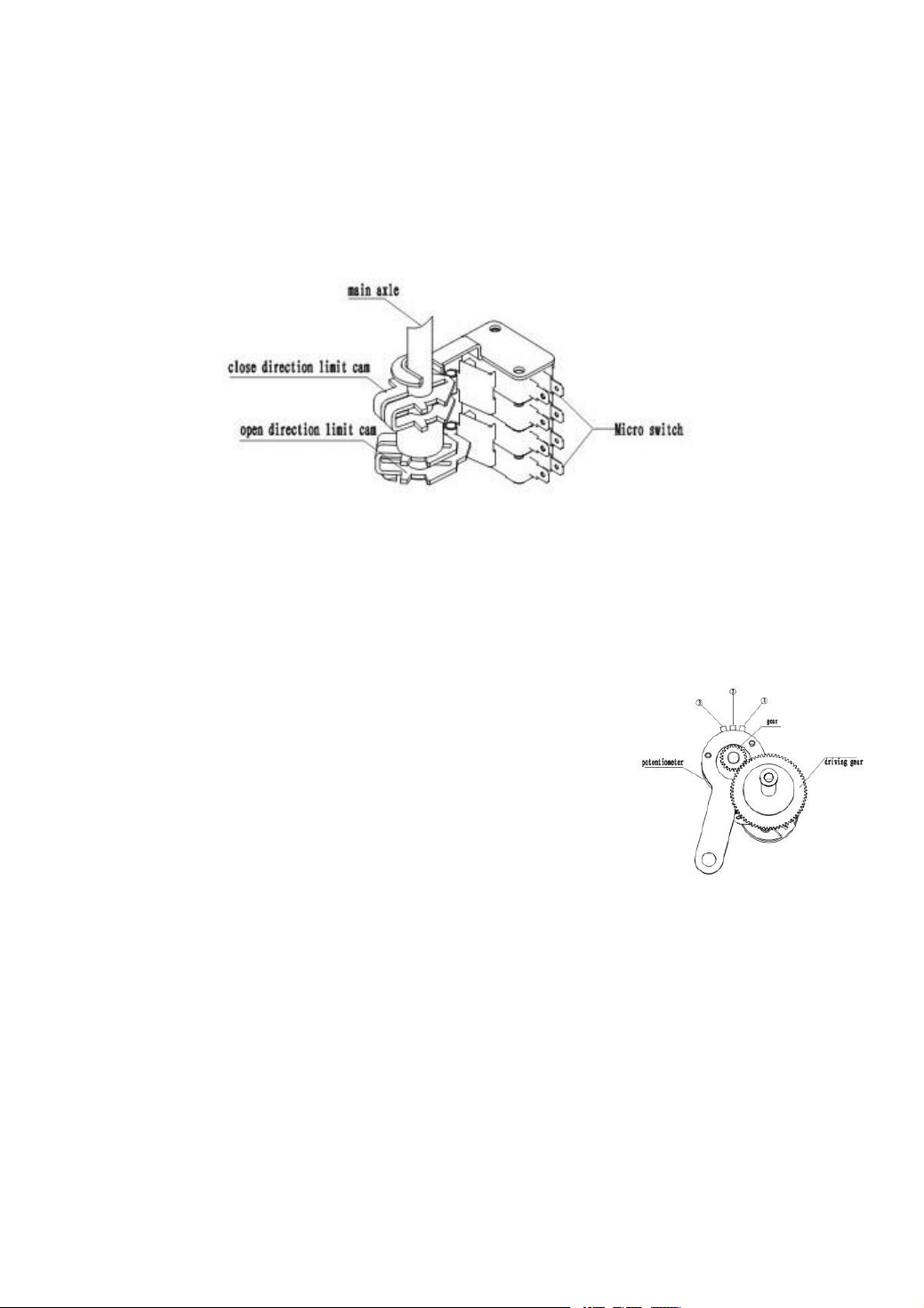
9.2 Adjustment of Travel Limit(see picture14)
Potentiometer, as output feedback signal , with 3 terminals, ② connect to
the slide arm of potentiometer. ①connect to the terminal whose resistance
decrease between the slide arm when actuator in opening movement.
③ connect to the terminal whose resistance decrease between the slide arm
when actuator when actuator in closing movement.
(Note: The potentiometer resistance should be not subzero、jump phenomenon.)
Turn valve to the full-open position by manual until limit switch move,
Move the electric actuator to the full-closed position by manual. And loosen locknut, turn cam (yellow open, red
close) until touch close limit switch (CLS) , then screw locknut. It’s the way to set the full-closed travel limit
position of electric actuator. Full-open position setting is the same way.
Picture 14
9.3 Adjustment of Potentiometer
measure with a multimeter , adjust the resistance between ② and ① between 35 Ω ~ 60 Ω .If incorrect,
adjusting by turning the drive gear of potentiometer.
9.4 Adjustment of Over torque Protection Device
At nominal working pressure, adjust limit switch cam until touch switch contact roller. If actual torque to
drive valve over the rating torque, cam axle will rotate in clockwise/anticlockwise direction, and drive the cam to
process over torque movement.
9.5 Adjustment of Indicator Plate
Set valve to full-closed position, loosen screws on glass cover, turn the window glass to aline the indicator
direction mark with indicator hand. And then tight screws
(Note:the indicator plate has been set before leaving factory )
Page 16

- 15 -
9.6 Proportion adjustable (PCU) Debug Description
9.6.1Technical parameters
① Input:
—Input signal:4~20mADC; 2~10VDC; 0~5VDC 0~10VDC; 1~5VDC
—Input resistance:250Ω
—Feedback signal:100Ω~10KΩ
② Output:
—Output signal:4~50mADC
—Load resistance: Max 750Ω
—Control output:Relay tip,250VAC,10A(Resistance load)
③ Resolution:Min 1/1000
④ Adjustment of dead zone:0.1%~4.5%
⑤ Working temperature:-10℃~60℃
⑥ Relative humidity:Max 90%(Non-Condensed)
⑦ Position transform precision:±0.5%~±1.5%
⑧ Dielectric Vol.Proof:1500AC /min(Input to output,Power supply to each)
⑨ Shock or impact(X,Y,Z):10g
10. Running Test
10.1 Manual Operation
Cut power before manual operation, turn the handwheel one circle, one side move the clutch handle in left
until occlude, continue to turn handwheel to decrease the opening (observe the opening by window glass).
10.2 Electric operation
Check the correspondence between the opening of actuator and valve by manual (full-open, full-closed) before
◎
electric operation;
◎Check the wiring,
◎After confirming the above situation, start electric operation
Page 17

- 16 -
★NOTE
★ Note: Debugging description of modulating model, please refer to the specification of the actuator controller
①Check wiring diagram, power supply, control signal.
②Don’t change the internal wiring.
③If the power supply is 3 phase, check the rotating direction.
④Enable the electric actuator lies in a half on/off position by manual, turn on electricity and input open signal.
⑤If the electric actuator runs to the open direction, the wiring is correct.
⑥If the running direction is opposite, change 2 pieces wiring in 3.
11、Maintenance
Lubrication: Because special Mo-based grease is long life and well resistance, so no need to refuel;
Regular operation: Drive and check the device regularly when valve works infrequently.
part.
 Loading...