

Page 1
• Safety Instructions
• Installation
• Warranty
Installation Manual
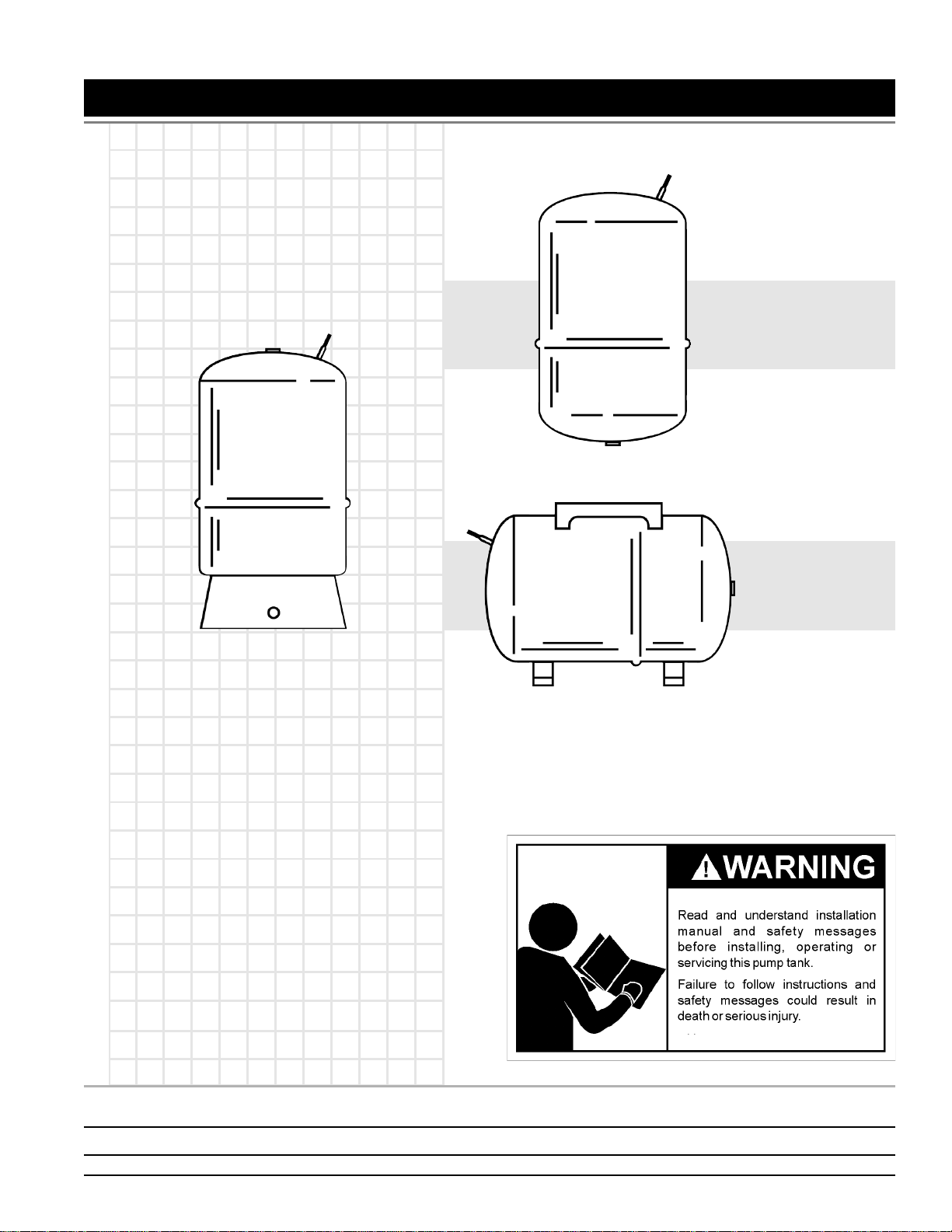
DIAPHRAGM WELL TANK
IN-LINE SERIES:
2-5 & 7 GALLON
VERTICAL SERIES:
14-20-32-36-52-86-96-1 19 GALLON
HORIZONTAL
SERIES:
7-14 & 20 GALLON
KEEP THIS MANUAL FOR FUTURE REFERENCE WHENEVER MAINTENANCE ADJUSTMENT OR SERVICE IS REQUIRED.
Water Systems • 4302 RALEIGH STREET • CHARLOTTE, NC 28213
PRINTED 0809 205621-001
1
Page 2
IMPORTANT INSTRUCTIONS BEFORE INSTALLATION
FAILURE T O FOLLOW THESE INSTRUCTIONS MAY CAUSE SERIOUS
BODIL Y INJURY AND/OR PROPER TY DAMAGE.
1. All piping and electrical wiring must adhere to state and local codes.
Check with appropriate community agencies, or contact your local
electrical and pump professionals.
2. Install tank as close as possible to the pump pressure switch to
reduce friction loss and elevation difference between the tank,
water supply main, and switch.
3. After installation, be sure the pressure switch is set low enough to
shut the pump off. If all valves are closed and the pressure switch
setting is too high, the pump will run continuously without water
flow causing overheating and damage to the pump.
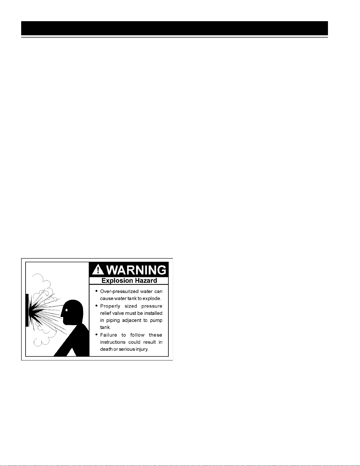
4. A pressure relief valve must be installed in the piping adjacent to the
pump tank.
5. The following may cause severe damage to tank and/or piping and
will void warranty.
• Failure to protect tank against below-freezing temperatures.
• Pumping chemicals or corrosive liquids.
• Pumping gasoline or other flammable liquids.
• Operation at pressures greater than rated pressure on data plate
with no relief valve.
• Pumping liquids hotter than 120°F .
Improper installation, adjustment, alteration, service or maintenance can
cause DEATH, SERIOUS BODIL Y INJUR Y , OR PROPERTY DAMAGE.
Refer to this manual for further assistance.
Failure to follow these instructions can cause tank to explode and result
in DEA TH, SERIOUS BODILY INJURY , OR PROPER TY DAMAGE.
Install a 100P .S.I. or less pressure relief valve directly into a fitting of the
plumbing. Position the valve downward and provide tubing so that any
discharge will exit only within 6 inches above, or at any distance below
the structural floor. Be certain that no contact is made with any live
electrical part. The discharge opening must not be blocked or reduced in
size under any circumstances. Excessive length, over 15 feet, or in use
of more than two elbows can cause restriction and reduce the discharge
capacity of the valve.
No valve or other obstruction is to be placed between the relief valve
and the tank. Do not connect tubing directly to discharge drain unless a
6” air gap is provided. T o prevent bodily injury or hazard to life, the valve
must be able to discharge large quantities of water should circumstances
demand. If the discharge pipe is not connected to a drain or other
suitable means, the water flow may cause property damage.
The Discharge Pipe:
• Must not be smaller in size than the outlet pipe size of the valve, or
have any reducing couplings or other restrictions.
• Must not be plugged or blocked.
• Must be installed so as to allow complete drainage of both the pressure
relief valve, and the discharge pipe.
• Must not have any valve between the relief valve and tank.
The complete pump, tank pressure relief valve, pressure switch and
piping system MUST be protected against below freezing temperature.
Failure to do so could cause tank to explode and result in DEATH,
SERIOUS BODILY INJUR Y , OR PROPERTY DAMAGE.
This pump tank is designed and intended for cold (ambient temperature)
water storage at a maximum pressure of 100 PSIG , any use other than
with cold water, or at a sustained or instant aneous pressure in excess
of 100 PSIG is UNSAFE. A pressure relief valve of adequate size must
be incorporated in the system. The relief valve must be selected to pass
the full capacity of the pump when the pressure in this tank is 100 PSIG
or more. Consult pump manufacturer for pump capacity at relief pressure.
The manufacturer of this tank does not accept any liability or other
responsibility for personal injury or property damage resulting from
improper use, installation, or operation of this tank, or of the system of
which it is a part.
The pump tanks are designed for operation on water systems with
working pressure not to exceed 100 PSI. Pressure exceeding this could
become hazardous, and will void any and all guarantees, either written,
or implied.
IMPORT ANT
It will be necessary to expel all air from piping after new installations,
repriming and after pumps have been disassembled for repair. T o purge
the air, first open a faucet the greatest dist ance from the pump. With the
pump being allowed to run, wait until a steady stream of water is
coming from the faucet. At this time, close the faucet for several short
intervals.
If, after this, air in the lines still occur, check on the suction side of the
pump for piping leaks.
When standard type tanks are replaced with this tank, all air charging
devices, bleeder orifices, and air volume controls must be removed.
The pump tank has been shipped with a factory precharge as indicated
on the tank label. If your pump start-up pressure is different from the
factory precharge, adjust the tank pressure with the empty tank to your
pump start-up pressure. This can be accomplished by simply bleeding
air from valve in the top of the tank with an accurate pressure gauge.
Using the same standard air charging valve in the top tank, a tire pump
can be used to raise the tank pressure. Raise the pressure slowly,
checking it periodically with an accurate tire pressure gauge, until the
desired pressure is reached.
2
Page 3
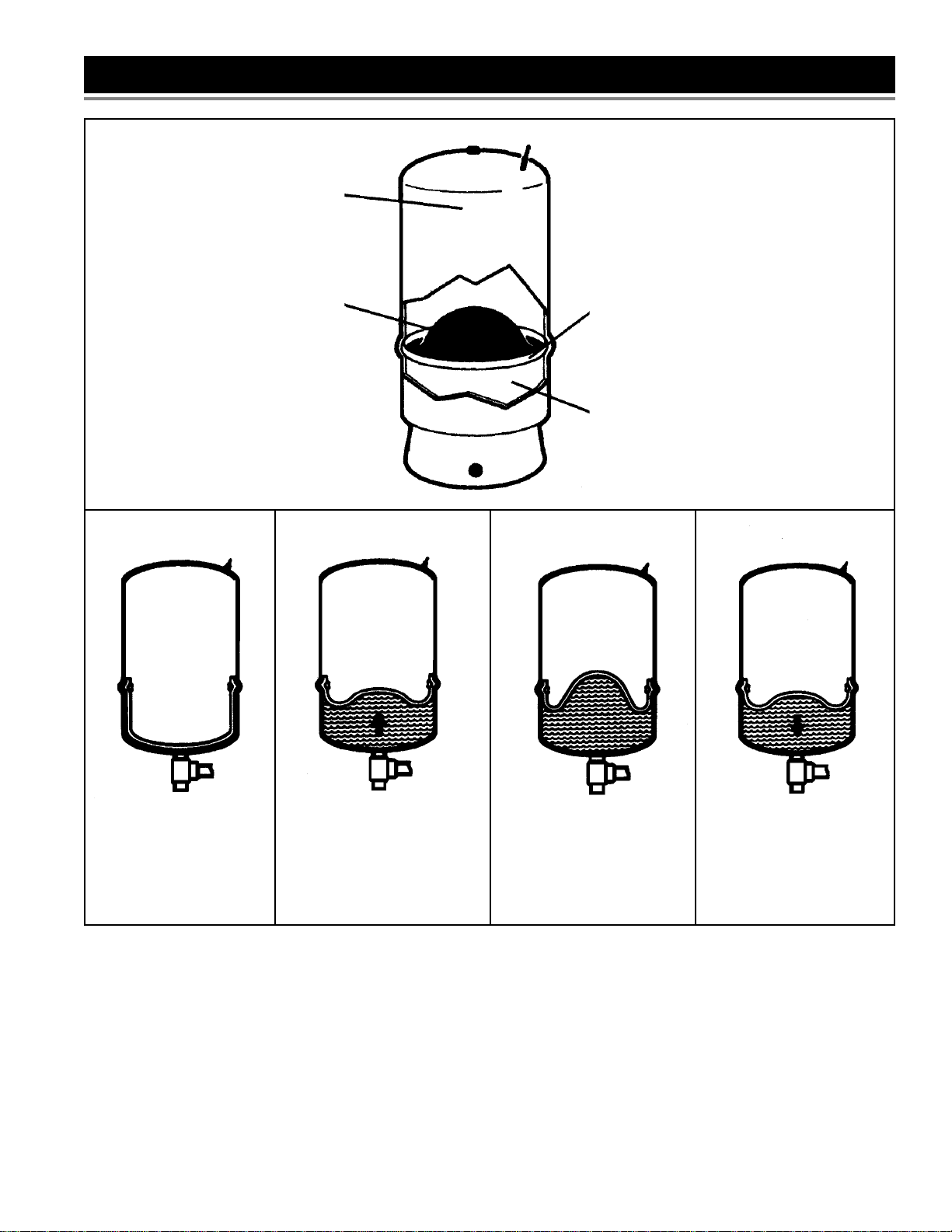
FEA TURES AND OPERA TING CYCLES
SHELL constructed of light-weight
drawn steel with epoxy finish provides
extra corrosion-resistance.
STRONG AND FLEXIBLE BUTYL
DIAPHRAGM assures dependable
tank service even with pressures up
to 100 PSI.
DIAPHRAGM SEAL consists of
locking retainer ring for positive
separation of air and water .
LINING protects inner shell against
rust in water reservoir.
ST ART-UP CYCLE
The diaphragm is pressed
against the bottom of the air
chamber
FILL CYCLE
Water is pumped into the
reservoir, which forces the
diaphragm upward into the air
chamber .
HOLD CYCLE
Pump attains cut-off pressure.
Diaphragm reaches uppermost
position. Reservoir is filled to
capacity.
3
DELIVERY CYCLE
Pump remains off while
pressure in air chamber forces
diaphragm downward to
deliver water.
Page 4

TANK SPECIFICATIONS
PCM20
PCM36
PCM52
PCM86
Capac ity
in G a ll o n s
2 0.7 0.6 --- 20 PSI 12-9/16 --- 8-3/8 --- 3/4 NPTM 5.0
5 1.6 1.4 --- 20 PSI 14-3/4 --- 11-3/8 --- 3/4 NPTM 9.0
7 2.5 2.1 --- 20 PSI 21-1/8 --- 11-3/8 --- 3/4 NPTM 14.0
14 5.2 4.3 3.7 38 PSI 24-3/4 2-1/4 15-3/8 --- 1” NPTF 25.5
20 7.4 6.2 5.4 38 PSI 32-3/4 2-1/4 15-3/8 --- 1” NPTF 30.0
36 13.3 11.1 9.7 38 PSI 32-3/8 2-1/4 20 --- 1” NPTF 43.5
52 19.2 16.1 14 38 PSI 38-5/8 2-1/4 23-3/8 --- 1-1/4” NPTF 75.0
86 31.8 26.7 23.2 38 PSI 58-3/4 2-1/4 23-3/8 --- 1-1/4” NPTF 103.0
119 44 37 32 38 PSI 61-1/4 2-1/2 26 --- 1-1/4” NPTF 164.0
7 2.5 2.1 --- 20 PSI 12-1/2 21-1/8 11-3/8 12-1/2 3/4 NPTM 14.5
20 7.4 6.2 5.4 38 PSI 17-3/8 27-1/8 15-3/8 14 1” NPTF 29.0
20 7.4 6.2 5.4 27 PSI 32-3/4 2-1/4 15-3/8 --- 1” NPTF 33.0
36 13.3 11.1 9.7 27 PSI 32-3/8 2-1/4 20 --- 1” NPTF 47.5
52 19.2 16.1 14 27 PSI 38-5/8 2-1/4 23-3/8 --- 1-1/4” NPTF 79.5
86 31.8 26.7 23.2 27 PSI 58-3/4 2-1/4 23-3/8 --- 1-1/4” NPTF 108.0
20 7.4 6.2 5.4 27 PSI 17-1/2 31-3/8 15-3/8 14 1” NPTF 33.5
Drawdown in Gallons Dimensions in Inc hes
20-40 PSI 30-50 PSI 40-60 PSI
Prechg.
Pressure
A B C D E
PCM20
Dischg.
Connection
Weight
In Pounds
Piping
PVC pipe is shown in the illustrations, but copper or galvanized steel
pipe may be used if desired. All piping must be clean and free of all
foreign matter. ALL JOINTS AND CONNECTIONS IN THE SYSTEM
MUST BE AIRTIGHT. A pin-hole leak will prevent proper operation of
system (this is the most common problem). Use thread compound on all
threads unless specified otherwise.
Draining for servicing or for Winter
The system should be drained before it is disconnected for servicing, or
if it is inoperative for an extended period of time, or if it is in danger of
freezing. T o Drain:
• Follow the instructions in your pump installation manual to drain the
pump.
• Open tank drain cock to drain tank.
• Drain all piping to a point 3 feet below ground level.
4
Page 5

DIAPHRAGM TANK INSTALLATION
All diaphragm tanks are recommended for clear water applications.
Vertical tanks are the most commonly used tanks. However , horizontal
tanks and in-line tanks may be used where space is more critical. See
T ank S pecifications for tank capacity.
• Enough rigid 1” PVC pipe and couplings to reach from pump to
pressure tank to service line.
• One male 1” PVC adapter
• One 1” X 1 1” tank cross
General Materials*
• Two 3/8” plugs
• One can PVC cement (read instructions carefully)
• One can thread compound (read instructions carefully)
• One 1” gate valve
• One 1/2” relief valve
• One 1/2” boiler drain
• One 1/2” street tee
Tools Needed for All Pump Installation
Pipe wrench, crescent wrench, 24-tooth hacksaw, round file or knife.
REMINDER: All joints and connections must be airtight. A single pin-hole leak will prevent the proper operation
of the system. Use thread compound on all threaded connections unless specified otherwise.
* list is for 1” piping installation, if you are installing 1-1/4” pipe change sizes accordingly.
TYPICAL SUBMERSIBLE PUMP INSTALLATION
STEP 1
Complete pump assembly and electrical connections as specified in
pump installation manual. Place tank in desired location and level it.
STEP 2
Thread tank tee PPTC10 into pressure tank so that the two 1/4” holes in
the tee face upward. Thread street tee into front of tank tee.
STEP 4
Thread pressure relief valve PPRV50 into top of street tee. Thread 1/2”
boiler drain into front of street tee. Cut and cement as many sections
and couplings of PVC pipe needed to connect 3/4” male PVC adapter to
pump discharge.
STEP 3
Thread 3/4” male PVC adapter into the inlet side of tank tee.
Complete installation should look like drawing below .
SUBMERSIBLE PUMP WITH VERTICAL T ANK
5
Page 6

TYPICAL JET PUMP INSTALLATION
STEP 1
Thread 10” X 1” nipple into pressure tank. Thread tank cross PPTC4 into
nipple so that the two 1/4” holes in tank cross face upward. Thread
street tee into front of tank cross. Thread pressure relief valve PPRV75
into top of street tee and thread 3/4” boiler drain into front of street tee.
STEP 2
Thread 1” male PVC adapter into the inlet side of tank cross.
pressure gauge PP100G into right 1/4” hole of tank cross. Cut and
cement as many sections and couplings of PVC pipe needed to connect
the 1” male PVC adapter to pump discharge.
Complete installation should look like the drawing below.
STEP 3
Thread one end of 1/4” X 3” brass nipple into bottom of pressure switch
PPS2040. Thread other end into left 1/4” hole of tank cross. Thread
NOTE: NO PRESSURE RELIEF V ALVE SHOWN ON THE JET PUMP WITH IN-LINE
BASE MOUNTED JET PUMP WITH VERTICAL T ANK
LMT series tanks come with a factory installed manifold which includes
the pressure switch and pressure gauge. This saves assembly cost
and extra fitting costs.
DRAWING AND JET PUMP MOUNTED ON VERTICAL TANK DRAWING .
6
Page 7

Setting the T ank Pressure
The tank pressure must be set 2 PSI lower than the pump cut-on pressure.
Check tank pressure with a standard air gauge valve at the top of the
tank as needed.
Other T ank Installations
Where space is a critical factor, the in-line t ank may be used or the pump
may be mounted on either the horizontal or vertical tanks. Various
installations are shown. Also, to increase tank capacity up to even
industrial levels, multiple tanks may be installed on the same line as
shown to the right. Consult your local pump professional for your
particular installation.
7
Page 8

WARRANTY
FIVE YEAR LIMITED W ARRANTY ON PUMP T ANKS
The “COMPANY” warrants this pump t ank in case of a leak within five (5) years from the date of purchase or in the absence of a Bill of
Sale verifying said date, from the date indicated on the model and rating plate affixed to this tank. In case of a defect, malfunction, or
failure to conform to this warranty , the Company will repair or replace this tank. No labor , installation, or freight (if any) charges are
included in this warranty . You must pay these costs.
Prior to return of the pump tank or part to the manufacturer for inspection, the Company will, if requested, ship a replacement pump tank
or part C.O.D. and later provide such reimbursement as subsequent inspection indicates is due under these warranties.
EXCLUSIONS AND LIMIT A TIONS OF THESE LIMITED WARRANTIES
1. The limited warranties provided herein are in lieu of any and all warranties, expressed or implied, including, but not limited to, implied
warranties of merchantability and fitness for a particular purpose; provided, however , that implied warranties are not disclaimed
during the five-year period from date of purchase. Some states do not allow limitations on how long an implied warranty lasts, so
the above limitation may not apply to you.
2. The company shall have no liability hereunder, either direct or contingent, for incident al or consequential damages. Some states do
not allow the exclusion or limitation of incidental or subsequential damages, so the above limitation or exclusion may not apply to you.
3. This warranty gives you specific legal rights, and you may also have other rights which vary from state to state.
4. These warranties shall be void and shall have no effect:
a. If the design or structure of the tank is, or is attempted to be, modified or altered in any way, including, but not limited to, by
attaching non-Company approved appliances or equipment.
b. If the tank is not properly installed in accordance with all local ordinances and regulations pertinent to tanks and the installation and
instruction manual provided with this tank.
c. If the pump tank is installed outdoors. This tank is intended for indoor installation only .
d. If the tank is not equipped with new pressure protective equipment required by local codes, but not less than a pressure relief
valve certified by a nationally recognized testing laboratory that maintains periodic inspection of production of listed equipment or
materials, as meeting the requirements for Relief V alves. This valve must be marked with a maximum set pressure not to exceed
the marked hydrostatic working pressure of the tank.
e. If the tank is not operated within the factory calibrated limits.
f. If leaks in the tank, or defects in other parts, arise as the result of improper use, negligence in operation, accident, or from inability
of the tank or any of its parts to function because of repairs, adjustments, or replacements improperly made outside the
Company’s factory , or because of fire, floods or lightning.
g. If the model and rating plate has been defaced or discarded and you do not have a Bill of Sale to verify the purchase date.
h. If (1) installed in an area where leakage of the tank or connections would result in damage to the area adjacent to the tank or (2)
where such a location is unavoidable, a suitable drain pan is not installed under the tank.
i. If the tank is used for any purpose other than a pump tank for space heating and cooling systems.
j. If the tank is used with pools, whirlpools, or hot tubs, or with any equipment or system that uses heavily chlorinated or otherwise
nonpotable water.
k. If leaks in the tank or defects in other parts occur as a result of the tank being exposed to a highly corrosive atmospheric condition.
l. If leaks in the tank or defects in other parts occur as a result of the tank containing and/or being operated with desalinated
(de ionized) water.
m. If leaks in the tank or defects in other parts arise as a result of sizing that does not comply with the manufacturer’s currently
published sizing guides or sizing recommended by the manufacturer.
n. If this pump tank or any part has been under water .
o. If a new certified pressure relief valve (rated 75 p.s.i. max.) is not installed and properly maintained.
5. Replacements and/or repairs furnished under these warranties do not carry a new warranty , only the unexpired portion of the
original warranty .
6. The terms of this warranty may not be varied by any person, whether or not purporting to represent or to act on behalf of the
Company .
7. In order to obtain service under these warranties you must promptly notify the installing contractor or dealer , giving the nature of the
problem and the model and serial number of the tank. If for any reason the installer or dealer cannot be located or fails to provide
satisfactory warranty service, you should write the Company with the above information.
8
 Loading...