

Page 1
Solar
control
SGS
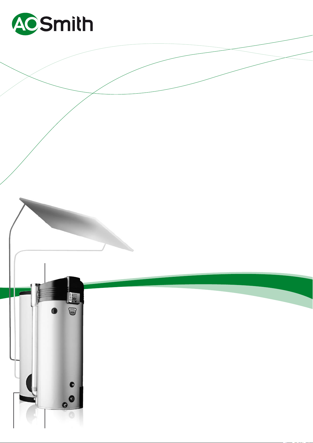
Condensing High Efficiency
Gas-Solar Water Heater
SGS - 28/30/50/60/80/100
Storage
Tank
SGS
Fully room sealed condensing high efficiency gas-solar water
heater (95 % gross) • Maximum solar contribution through fully
integrated intelligent solar controller • 1 control and display unit
for the complete installation • Extra solar contribution possible up
to 40 % compared to standard solar systems • Suitable in combination
with storage tanks up to 3000 liters • Flexible ue options (maximum
lenght 115m) • Thermocontrol for easy exible control / fault
diagnosis • Programmable for legionella purge cycle • All models
suitable for natural or LP gas • Meets latest EPC standards:
SGS 28-60 : 0,902 • Scale formation is reduced through the improved
design and location of the heat exchanger • Very easy maintenance
and installation • SGS 80 - SGS 100 standard applied with powered
anodes • Remote control connection • Voltage-free contact for
general fault indication • Unvented kits are optional
Innovation has a name.
Page 2
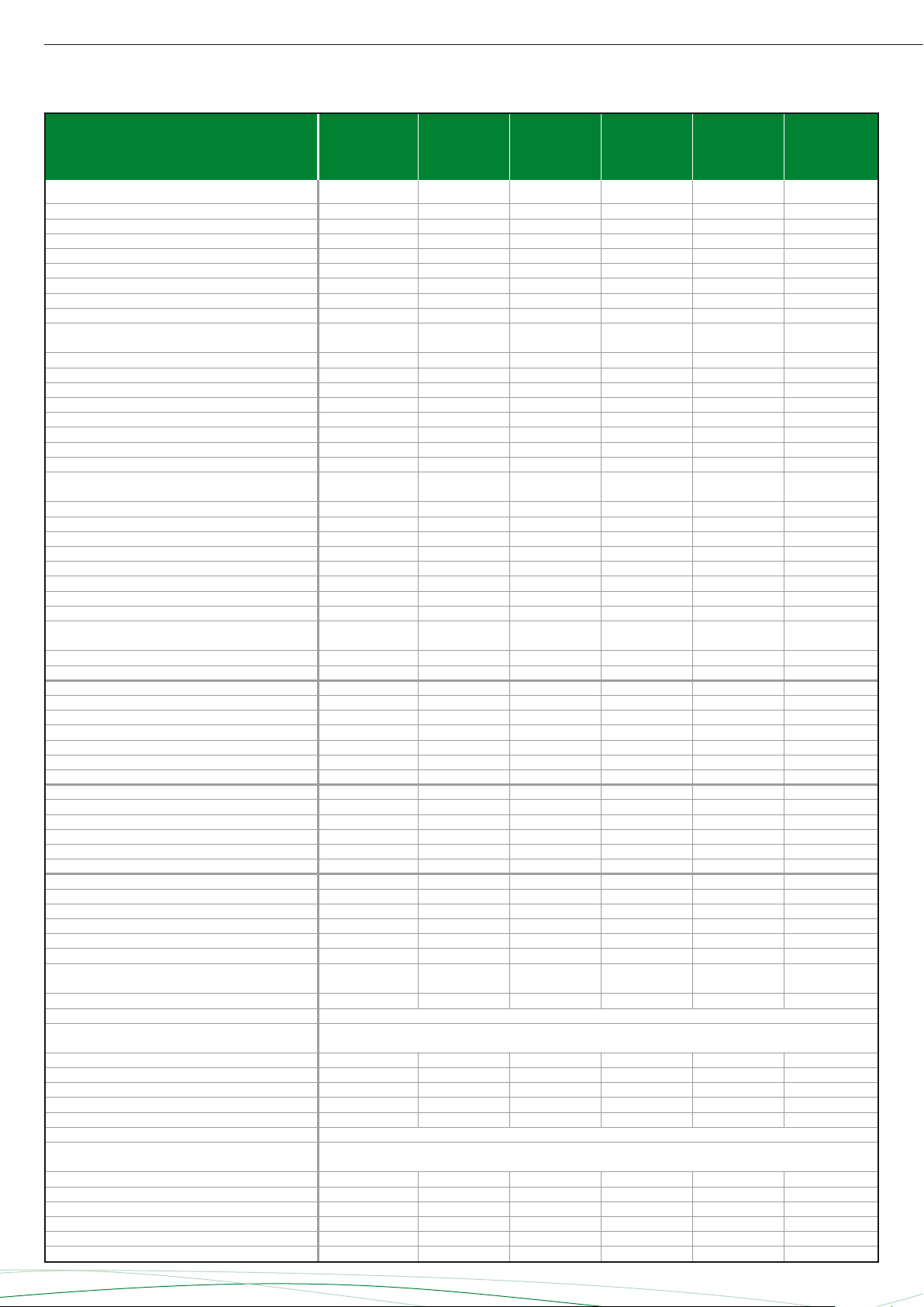
SGS
Technical specifications
SGS 28
SGS 30
SGS 50
SGS 60
SGS 80
SGS 100
Gas data natural gas 2H (G20)
Input* kW 32.1 34.5 52.6 63.2 86.6 105.5
Output kW 30.5 32.7 48.8 59.6 81.9 99.8
Inlet pressure mbar 20 20 20 20 20 20
Burner pressure mbar 8.5 8.5 8.5 11.5 6.0 6.0
Gas consumption ** m
Diameter injector mm 4.90 5.10 7.00 7.10 6.30 6.80
Max. flue gas temperature °C 70 50 75 75 50 50
Flue gas discharge kg/h 56.8 61.1 85.4 101.4 141.9 164.3
3
/h 3.1 3.3 5.0 6.0 8.3 10.1
Gas data butane gas 3+ G30
Input* kW 30.7 32.8 50.6 59.4 - Output kW 29.8 31.8 48.1 56.9 - Inlet pressure mbar 30 30 30 30 - Burner pressure mbar - - - - - Gas consumption ** kg/h 2.2 2.4 3.7 4.3 - Diameter injector mm 2.50 2.60 3.40 3.80 - Max. flue gas temperature °C 70 50 75 75 - Flue gas discharge kg/h 60.0 62.2 86.0 101.9 - -
Gas data propane gas 3+ G31
Input* kW 29.0 30.9 50.3 59.1 84.8*** 103.3***
Output kW 28.1 29.8 47.7 56.9 81.9*** 99.8***
Inlet pressure mbar 37 37 37 37 30*** 30***
Burner pressure mbar - - - - 13.0*** 13.0***
Gas consumption ** kg/h 2.1 2.2 3.6 4.2 6.1*** 7.4***
Diameter injector mm 2.50 2.60 3.40 3.80 4.70*** 5.10***
Max. flue gas temperature °C 70 50 75 75 50*** 50***
Flue gas discharge kg/h 54.3 56.5 85.1 101.0 142.1*** 176.4***
Draw-off capacity
Storage capacity l 217 368 368 368 460 460
Max. temperature setting °C 80 80 80 80 80 80
T
= 10ºC / T
cold
30 min ∆T=44°C l 457 642 784 897 1139 1296
60 min ∆T=44°C l 755 961 1261 1461 1939 2270
90 min ∆T=44°C l 1053 1280 1738 2043 2737 3245
120 min ∆T=44°C l 1350 1599 2215 2625 3540 4220
Continuous ∆T=44°C l/h 595 638 954 1164 1601 1950
Heating-up time ∆T=44°C min 22 35 23 19 17 14
30 min ∆T=50°C l 402 565 690 773 1002 1140
60 min ∆T=50°C l 664 846 1110 1286 1706 1998
90 min ∆T=50°C l 926 1126 1530 1798 2411 2856
120 min ∆T=50°C l 1188 1407 1950 2310 3115 3714
Continuous ∆T=50°C l/h 524 562 840 1025 1409 1716
Heating-up time ∆T=50°C min 25 39 26 22 20 16
30 min ∆T=55°C l 366 513 627 703 911 1036
60 min ∆T=55°C l 604 769 1009 1169 1551 1816
90 min ∆T=55°C l 842 1024 1391 1634 2191 2596
120 min ∆T=55°C l 1080 1279 1772 2100 2832 3376
Continuous ∆T=55°C l/h 476 511 763 932 1281 1560
Heating-up time ∆T=55°C min 27 43 29 24 22 18
set
= 65ºC
Electrical data
Power consumption W 275 275 275 275 600 690
Power supply VAC/Hz 230(-15% / +10 % VAC)
General
Fan rotational speed at ignition r.p.m. 4500 4500 4500 4500 2790 3120
Working speed fan r.p.m. 5000 5400 6000 6660 5100 5700
Pressure differential Pa 635/605 855/825 885/855 1085/1055 1005/975 1145/1115
Diameter of air restrictor mm 23 23 28 29 36 38
Anodes - 4 4 4 4 2-electric 2-electric
Maximum working pressure bar 8
Shipping data
Empty weight kg 177 214 214 214 480 480
Max. weight kg 394 582 582 582 940 940
Weight incl. packaging kg 197 234 234 234 491 491
Width packaging mm 870 870 870 870 920 920
Height packaging mm 1550 2080 2080 2080 2060 2060
Depth packaging mm 950 950 950 950 1020 1020
*** 3p (G31)
* Gas data on gross value
** Gas consumption at 15°C en 1013,25 mbar
Page 3
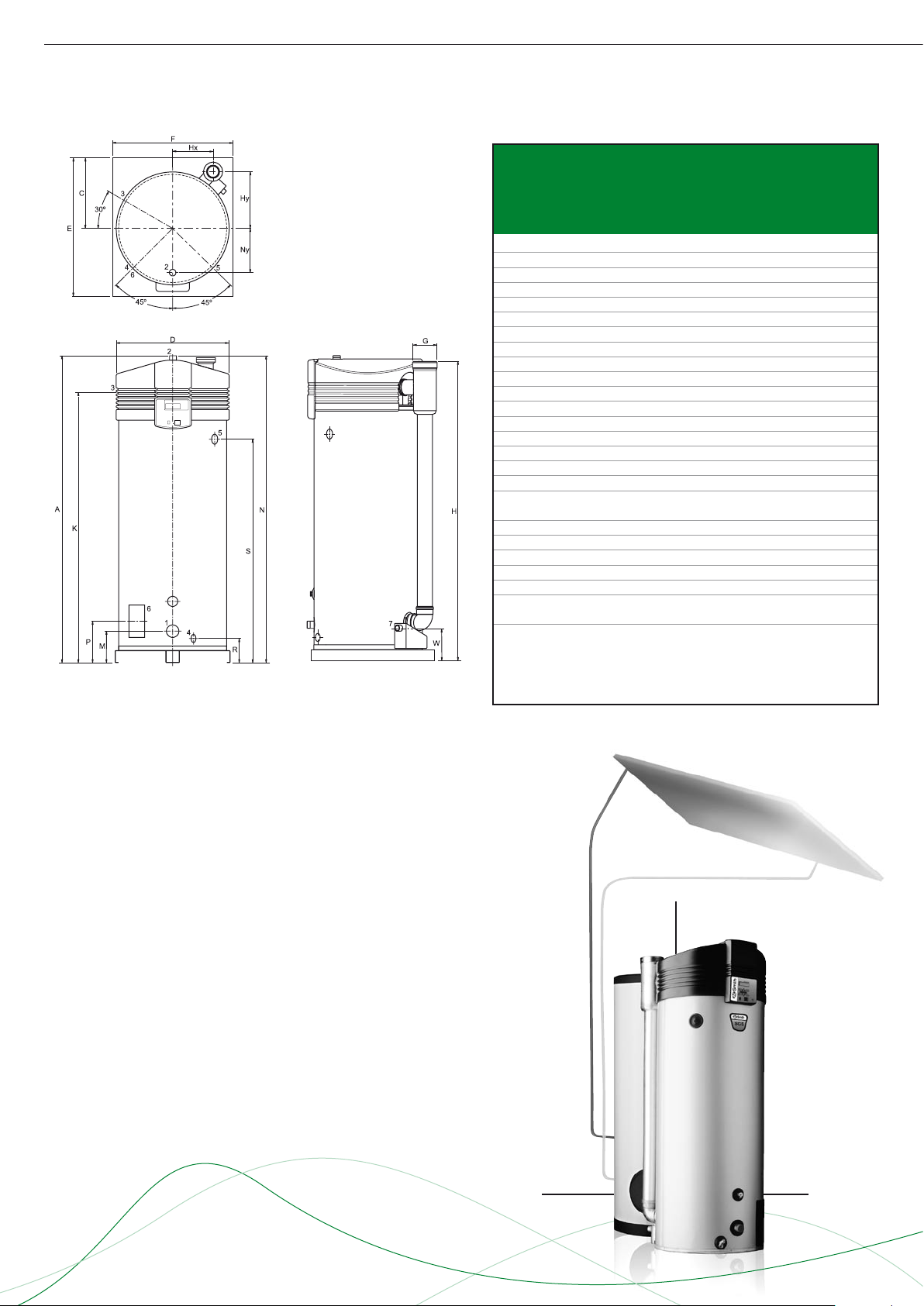
SGS
Dimensions SGS 28-60
SGS 28
SGS 30
SGS 50
SGS 60
A 1485 2005 2005 2005
C 490 490 490 490
D 705 705 705 705
E 925 925 925 925
F 850 850 850 850
G 80/125 100/150 100/150 100/150
H 1460 2000 2000 2000
Hx 265 265 265 265
Hy 375 375 375 375
K 1365 1895 1895 1895
M 265 255 255 255
N 1485 2005 2005 2005
Ny 205 205 205 205
P 265 270 270 270
R 180 170 170 170
S 995 1505 1505 1505
W 220 240 240 240
1 Cold water connection R11/2
2 Hot water connection R1
3 Gas valve connection Rp
4 Drain valve connection
5 Temperature and pressure valve 1 / 11.5 NPT
6 Inspection flange 95x70
7 Condensate drain Ø40 (SGS 28)
Rp1 (SGS 30-60)
1
/2
3
/4
3
/4
On all SGS units 3 year warrranty is appliccable on the tank
and 1 year on all parts.
Storage
Tank
Solar
control
SGS
Page 4

SGS
Dimensions SGS 80-100
SGS 80
SGS 100
A 2060 2060
C 530 530
D 850 850
E 1000 1000
F 900 900
G 130/200 130/200
H 2015 2015
Hx 310 310
Hy 440 440
K 1855 1855
M 225 225
N 2060 2060
Ny 205 205
P 290 290
R 225 225
S 1425 1425
W 240 240
1 Cold water connection R11/2
2 Hot water connection R1
3 Gas valve connection Rp
4 Drain valve connection
5 Temperature and pressure valve 1 / 11.5 NPT
6 Inspection flange 95x70
7 Condensate drain Rp1
1
/2
3
/4
3
/4
On all SGS units 3 year warrranty is appliccable on the tank
and 1 year on all parts.
Storage
Tank
Solar
control
SGS
Page 5

SGS
Installation diagrams
Vented
Unvented
1 Pressure reduce valve
2 Inlet security group
3 Temperature and pressure valve
4 Stop valve
5 Non-return valve
6 Circulation pump
9 Drain valve
10 Gas cock
11 Isolating valve
12 Temperature gauge
13 Condense drain
14 Hot water outlets
16 Expansion vessel
17 Three way valve
18 Water cistern
19 Float valve
23 Over pressure security group
26 Air bleed
37 Flowmeter
38 Pompmodule solar
S1 T-collector
S2 T-tank
S3 T-top tank
S4 T-return solar
A Cold water supply
B Hot water outlet
C Circulation pipe
D Gas supply
E Water overflow
F Coil inlet
G Coil outlet
H Expansion pipe
Page 6

SGS
Electrical diagram SGS 28-60
COMPONENTS CONTROLLER
A Controller
B Ionisation rod
C Glow ignitor
D Gas control
E Burner earth connection
F Extra ON-mode switch
G Continuous pump
H Program controlled pump
J Extra error signal
K Isolating transformer
L Double-pole mains switch
M On/Off switch control
N Display
O Fan
P Temperature sensor
(T2 - bottom of tank)
Q Dummy
R Temperature sensor
(T1 - top of tank)
S Selection resistor
T Pressure switch
U Controller solarsystem (BUS-link)
F1 Fuse
F3 Fuse
CONNECTIONS MAIN CONTROLLER
1 X5
2 X
3 - n.a.
4 - n.a.
5 X
6 X
7
8 L
9 N
10 N
11 L
12
13 X
14 X
15
16 N
17 L
18
19 N
20 L
21
22
23 L
24 N
BUS-link
6
3
External ON / OFF
4
5 Continuous pump
4 Program controlled pump
2
1 Extra error signal
Isolating transformer
2
(primary side)
Isolating transformer
3
(secundary side)
1 Power supply
COMPONENTS SOLAR CONTROLLER
AA Controller
BB Pump solar system (ON / OFF)
CC Pumps solar system (modulating)
DD Temperature sensor
(S1 - solar collector)
EE Temperature sensor (S2 - tank)
FF Q/T-measuring (incl. temperature sensor S4 - return solar collector)
GG Controller (BUS-link)
HH Temperature sensor
(S3 - top tank)
F2 Fuse
CONNECTIONS SOLAR CONTROLLER
1
2 L Power supply
3 N
4 - n.a.
5 - n.a.
6 - n.a.
7
8 L
9 N
10 N
11 L
12 - (modulating)
13
14 - n.a.
15 - n.a.
16 - n.a.
17 - n.a.
18 - n.a.
19 - n.a.
20 - n.a.
1 n.a.
2 n.a.
J3
3 n.a.
4 n.a.
1 Power supply 5V
2 Sensor return
J12 solar collector (S4)
3 Earth
4 Flow signal
1 n.a.
J13
3 n.a.
4 Sensor solar collector (S1)
1 Sensor top tank (S3)
J14
3 Sensor top tank (S3)
4 Sensor tank (S2)
J15
2 n.a.
J16
2
1 n.a.
J17 2 n.a.
3 n.a.
Pump solar system
1
(ON / OFF)
2 Pump solar system
2 Sensor solar collector (S1)
2 Sensor tank (S2)
1 n.a.
1
BUS-link
Page 7

SGS
Electrical diagram SGS 80-100
COMPONENTS CONTROLLER
A Control
B Ionisation rod
C Glow ignitor
D Gas control
E Burner earth connection
F Program controlled pump
G Continuous pump
H Extra error signal
J Isolating transformer
K Double-pole mains switch
L ON / OFF switch control
M Display
N Fan
O Temperature sensor
(T2 - bottom of tank)
P Dummy
Q Temperature sensor
(T1 - top of tank)
R Selection resistor
S Pressure switch
T Potentiostat
U Frequency controller
V RS-485 interface
W Electric anodes
X Signaling for electric anodes
Y Mains choke and EMC-filter
Z Solar control system (BUS-link)
F1 Fuse
F3 Fuse
CONNECTIONS MAIN CONTROLLER
1 X5
2 X
3 L
4 N
5
6 L
7 N
8 X
9 X
10 N
11 L
12
13 X
14 X
15
16 N
17 L
18
19 N
20 L
21
22
23 L Power supply
24 N
BUS-link
6
5
Potentiostat
4 Frequency controller
3
External ON / OFF
4
3 Program controlled pump
1
2 Extra error signal
Isolating transformer
2
(primary side)
Isolating transformer
1
(secundary side)
COMPONENTS SOLAR CONTROLLER
AA Control
BB Pump solar system (ON / OFF)
CC Pump solar system (modulating)
DD Temperature sensor
(S1 - solarcollector)
EE Temperature sensor (S2 - tank)
FF Q/T-measuring (incl. temperature
sensor S4 - return solar collector)
GG Control (BUS-link)
HH Temperature sensor
(S3 - top tank)
F2 Fuse
CONNECTIONS SOLAR CONTROLLER
1
2 L Power supply
3 N
4 - n.a
5 - n.a
6 - n.a
7
8 L
9 N
10 N
11 L
12 - (modulating)
13
14 - n.a
15 - n.a
16 - n.a
17 - n.a
18 - n.a
19 - n.a
20 - n.a
1 n.a
2 n.a
J3
3 n.a
4 n.a
1 Power supply 5V
2 Sensor return
J12 solar collector (S4)
3 Earth
4 Flow signal
1 n.a
J13
3 n.a
4 Sensor solar collector (S1)
1 Sensor top tank (S3)
J14
3 Sensor top tank (S3)
4 Sensor tank (S2)
J15
2 n.a
J16
2
1 n.a
J17 2 n.a
3 n.a
Pump solar system
1
(ON / OFF)
2 Pump solar system
2 Sensor solar collector (S1)
2 Sensor tank (S2)
1 n.a
1
BUS-link
Page 8

X
Y
V
W
X
Y
V
W
W
Y
V
X
Z
Y
T
X
Flue systems SGS
Installation options
B23
C33
C13
A SGS water heater should be installed according category B23,
C13, C33, C43 or C53*.
SGS 28
SGS 30
SGS 50
SGS 60
SGS 80
Concentric
Diameter (mm) 80/125 100/150 100/150 100/150 130/200 130/200
Max. length (m) 40 40 40 15 15 15
Max. 45/90° bends 7 7 7 4 3 3
Parallel (standard diameter)
Diameter (mm) 80 100 100 100 130 130
Max. length (m) 25 80 45 25 115 60
L
/bend 90° (m) 3,9 4,6 4,6 4,6 2,4 2,4
equivalent
L
/bend 45º (m) 1,1 1,2 1,2 1,2 1,4 1,4
equivalent
Parallel (larger diameter for more length)
Diameter (mm) 100 130 130 130 150 150
Max. length (m) 100 100 100 100 100 100
L
/bend 90º (m) 4,6 2,4 2,4 2,4 2,6 2,6
equivalent
L
/bend 45º (m) 1,2 1,4 1,4 1,4 1,6 1,6
equivalent
* All SGS are also approved for installations where the unit is supplied
without venting materials (C63).
SGS 100
Concentric flues
It is not permitted to use more than the specified number of
bends, even when the duct is shorter than the maximum
length. A 45° bend is equivalent to a 90° bend.
C53
C43
Flue systems SGS
Minimum space requirements
SGS 28-60
SGS 80-100
Parallel flues
- The maximum permissible length should be reduced by the
equivalent length of each bend. (Note: for a parallel installation
this means that 3 changes in direction amount to 6 bends
(3 in the supply duct and 3 in the flue).
- The maximum length also applies if a parallel installation has
different supply and flue duct lengths (B23, C53).
- Combined flues (C43) shall be fitted with a condensate drain.
Note: horizontal flue runs must be installed with a fall of at least
5 mm per metre.
SGS 28
SGS 30
SGS 50
SGS 60
SGS 80
Minimal space for wall duct (mm)
Ø80/125 Ø100/150 Ø100/150 Ø100/150 Ø130/200 Ø130/200
V 550 550 550 550 640 640
W 725 790 790 790 940 940
X 1630 2170 2170 2170 2230 2230
Y 1460 1480 1480 1480 1620 1620
Y * 1010 1030 1030 1030 1170 1170
Minimal space for roof duct (mm)
V 1305 1500 1500 1500 1730 1730
W 680 1035 1035 1035 1120 1120
X 3060 3420 3420 3420 3620 3620
X ** 2110 2470 2470 2470 2670 2670
Y 1575 1415 1415 1415 1560 1560
Y ** 625 465 465 465 610 610
SGS 100
For the parts numbers of components and flue gas ducts, etc.
please refer to the “Maintenance and accessories” chapter.
* Distance without concentric pipe between bend and wall duct.
** Distance without concentric pipe between appliance and roof duct.
Data subject to change INT/1108/SGS/02
Terms and conditions apply, please refer to our website.
www.aosmithinternational.com
 Loading...