

Page 1
SGE
Condensing Gas-Solar
Water Heater
SGE - 40/60
0311 166 / 07-2013
Installation, User and Service
Manual
Innovation has a name.
Page 2

your installer
A.O. Smith UK, Unit B8 Amstrong Mall,
Southwood Business Park, Farnborough, Hampshire GU14 0NR
www.aosmith.co.uk
“A.O. Smith Water Heaters” is a trading name of Advance Services (Sales) Ltd. Reg.
Page 3
E1
Power
n.a.
n.a.
not applicable
Pump (solar)
not applicable
not applicable
L N - - - -
- - L3 N L4 -
- - - - - - 1 2 3 4 5 6 7 8 9
10
11
12
13
14
15
16
17
18
19
20
not applicable
Sensor S
1
not applicable
Sensor S
1
not applicable
Sensor S
2
not applicable
Sensor S
2
not applicable not applicable not applicable not applicable
Power 5V
Sensor S
4
Flow signal
not applicable not applicable
BUS-link
BUS-link
J13
J14
J3
J12
J15
J16
1 2 3 4 1 2 3 4 1 2 3 4 1 2 3 4 1 2 1
2
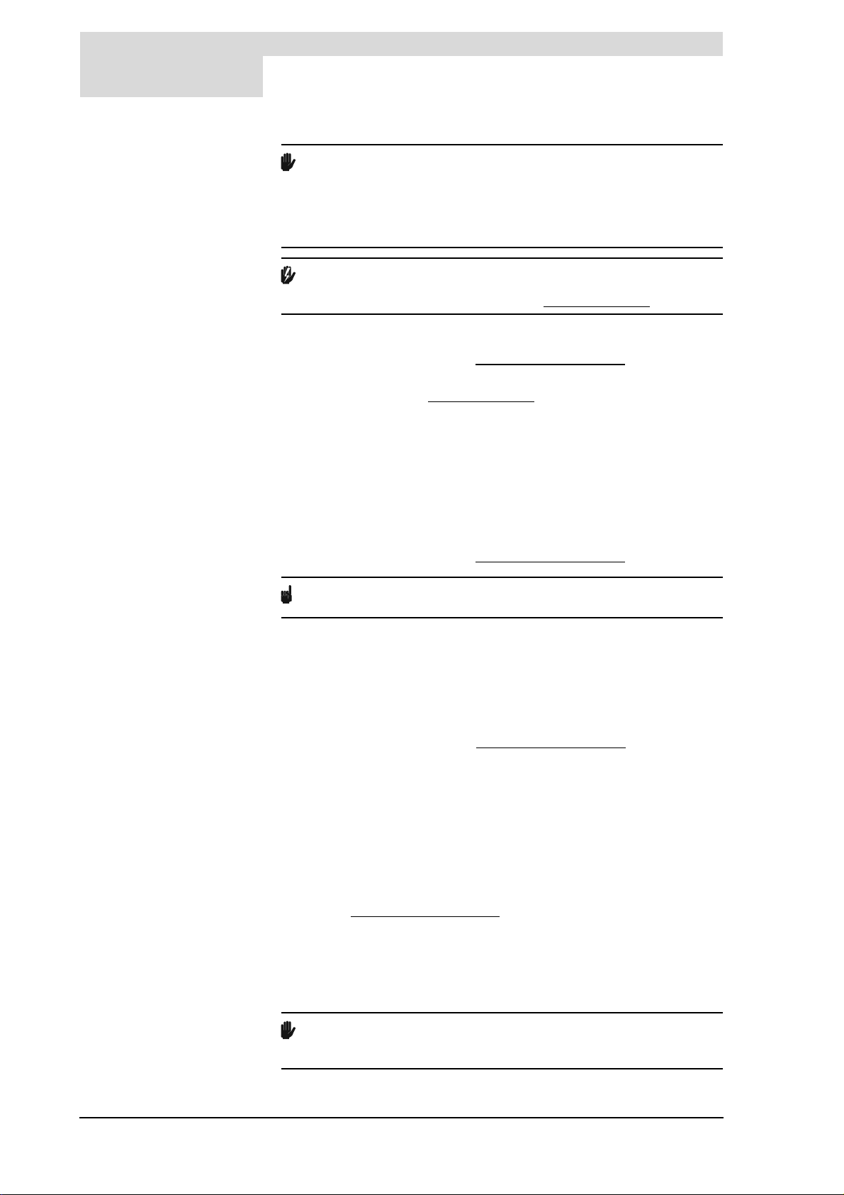
Errata
The amendments below apply to:
the preparation of the electrical connection of the solar heating control (3.12.1 "Preparation");
finishing maintenance (15.6 "Finalizing maintenance");
the electrical diagram of the solar heating control (17.4 "Electrical diagram solar heating system").
These instructions supersede the previous instructions of the solar heating control.
3.12.1
Preparation
Remove the cover (snap-on type) from the terminal block of the solar heating control.
This has the following terminals:
15.6 Finalizing
maintenance
To finalize the maintenance, carry out the following steps:
1. Fill the water heater (5 "Filling").
2. Start the water heater (9 "Starting the water heater").
3. Check the CO2 value (3.12.3 "CO2 adjustment").
4. Check the switching pressure of the pressure switch. (3.12.4 "Switching pressure
measurement")
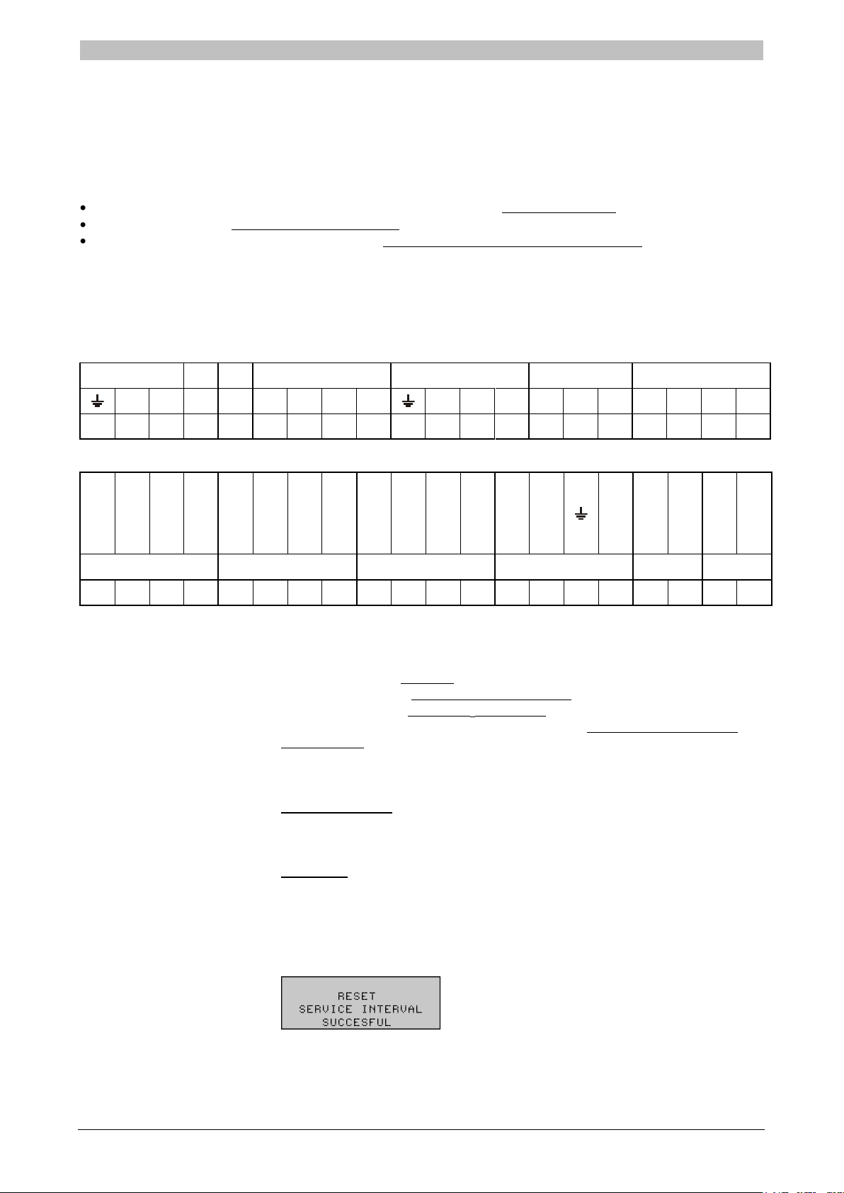
5. Erase the message SERVICE REQUIRED. The displayed message can be reset in
either of two ways.
1. Temporary reset:
To postpone the message, press RESET once. The message will reappear on the
display 7 days later.
2.Full reset:
To fully reset the message, press and hold both RESET and ENTER at the same
time for 5 sec.
On completion of the full reset of the message, the message below will appear on the
display. This message will NOT be shown after a temporary rest of the message.
Page 4
E2
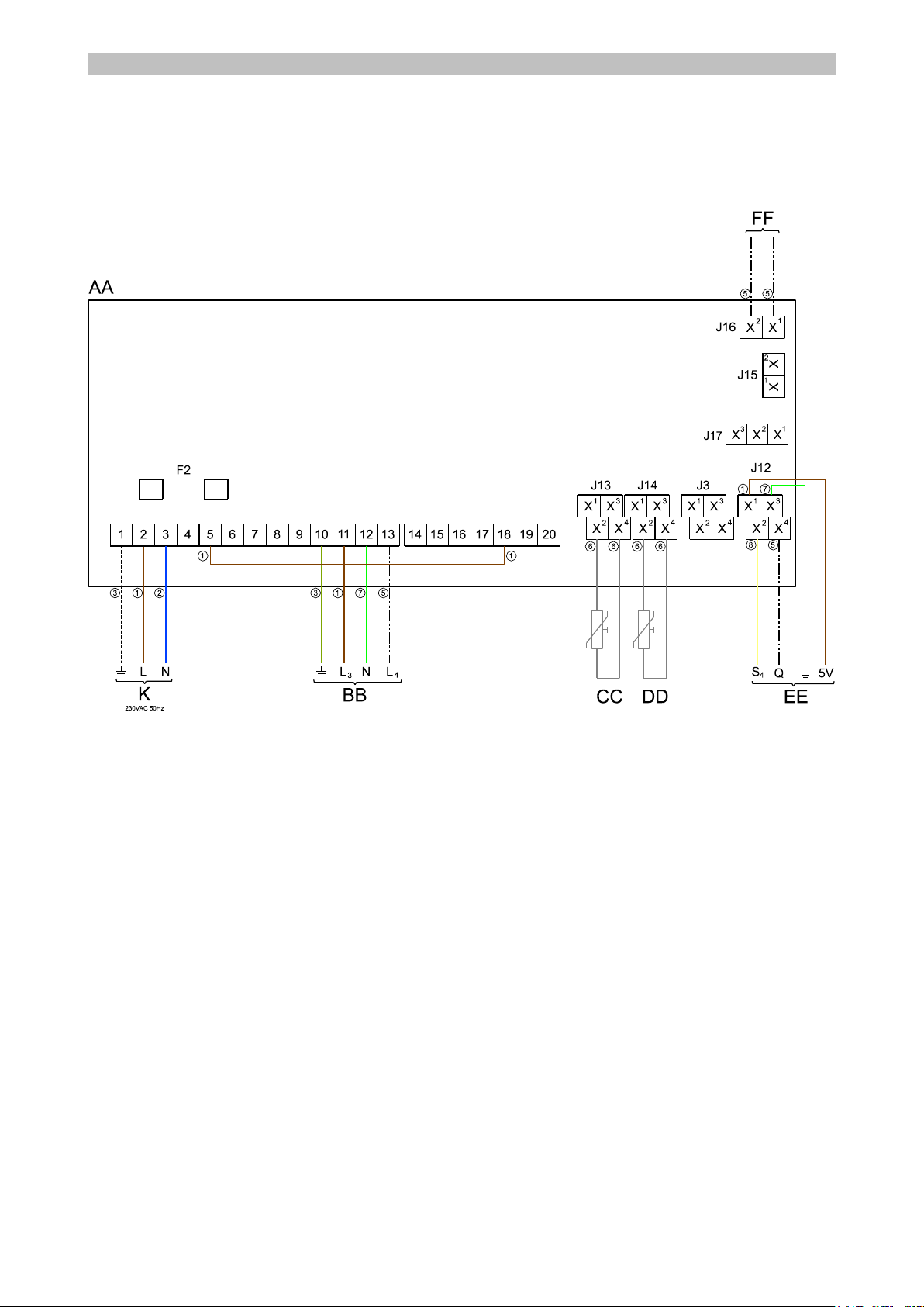
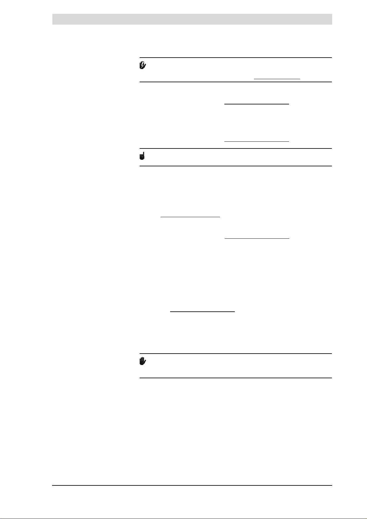
17.3 Electrical diagram Electrical diagram
solar heating
system
1 = brown, 2 = blue, 3 = yellow / green, 4 = black, 5 = white, 6 = grey / beige, 7 = green, 8 = yellow
Page 5

E3
TERMINAL BLOCK CONNECTIONS
Earth
N Neutral
L Live input of the controller
L3 Live input for the solar heating system modulating pump
L4 Modulating output of the solar heating system modulating pump
COMPONENTS
AA Controller
BB Solar heating system pump (modulating)
CC Temperature sensor (S1 - solar collector)
DD Temperature sensor (S2 - tank)
EE Combined Q/T sensor
(incl. temperature sensor S4 - solar collector return)
FF Communication between the water heater controller and the solar
Heating system controller (BUS-link)
K Double-pole isolator
CONTROLLER CONNECTIONS
J12 Connection of combined Q/T sensor (1-2-3-4)
J13 Connection of temperature sensor S1 (2-4)
J14 Connection of temperature sensor S2 (2-4)
J16 Connection of BUS-link communication
F2 Fuse (T 3.15A - 250 V)
Page 6
gis
Read this manual carefully
Trademarks
Liability
Warning
Read this manual carefully before starting the water heater. Failure to read
the manual and to follow the printed instructions may lead to personal injury and
damage to the water heater.
Copyright © 2013 A.O.Smith Water Products Company
All rights reserved.
Nothing from this publication may be copied, reproduced and/or published by
means of printing, photocopying or by whatsoever means, without the prior
written approval of A.O.Smith Water Products Company.
A.O.Smith Water Products Company reserves the right to modify specifications
stated in this manual.
Any brand names mentioned in this manual are registered trademarks of their
respective owners.
A.O.Smith Water Products Company accepts no liability for claims from third
parties arising from unauthorised use, use other than that stated in this manual,
and use other than in accordance with the General Conditions registered at the
Chamber of Commerce.
Refer further to the General Conditions. These are available on request, free of
charge.
Although considerable care has been taken to ensure a correct and suitably
comprehensive description of all relevant components, the manual may
nonetheless contain errors and inaccuracies.
Should you detect any errors or inaccuracies in the manual, we would be
grateful if you would inform us. This helps us to further improve our
documentation.
More information
If you have any comments or queries concerning specific aspects related to the
water heater, then please do not hesitate to contact:
A.O.Smith Water Products Company
PO Box 70
5500 AB Veldhoven
The Netherlands
Telephone: 0870-AOSMITH
0870-2676484
General: +31 40 294 25 00
Fax: +31 40 294 25 39
E-mail: info@aosmith.nl
Website: www.aosmith.co.uk
In the event of problems with your gas, electricity or water supply connections,
please contact the supplier/installation engineer of your installation.
Instruction manual SGE 3
Page 7

gis
4 Instruction manual SGE
Page 8

gis
Contents
1 Introduction - - - - - - - - - - - - - - - - - - - - - - - - - - - 9
1.1 About the water heater - - - - - - - - - - - - - - - - - - - - - - - - - - - 9
1.2 What to do if you smell gas - - - - - - - - - - - - - - - - - - - - - - - - - 9
1.3 Regulations - - - - - - - - - - - - - - - - - - - - - - - - - - - - - - - - 9
1.4 Target groups - - - - - - - - - - - - - - - - - - - - - - - - - - - - - - 10
1.5 Maintenance - - - - - - - - - - - - - - - - - - - - - - - - - - - - - - - 11
1.6 Notation conventions - - - - - - - - - - - - - - - - - - - - - - - - - - - 11
1.7 Overview of this document - - - - - - - - - - - - - - - - - - - - - - - - 12
2 Working principle of the water heater - - - - - - - - - - - - - 13
2.1 Introduction - - - - - - - - - - - - - - - - - - - - - - - - - - - - - - - 13
2.2 General working principle of the water heater - - - - - - - - - - - - - - - 13
2.3 Water heater operating cycle - - - - - - - - - - - - - - - - - - - - - - - 14
2.4 Protection for the water heater - - - - - - - - - - - - - - - - - - - - - - 15
2.5 Safety of the installation - - - - - - - - - - - - - - - - - - - - - - - - - 16
2.6 Protection for the solar heating system - - - - - - - - - - - - - - - - - - 17
2.7 Safety of the solar heating system - - - - - - - - - - - - - - - - - - - - 18
3 Installation - - - - - - - - - - - - - - - - - - - - - - - - - - - 19
3.1 Introduction - - - - - - - - - - - - - - - - - - - - - - - - - - - - - - - 19
3.2 Packaging - - - - - - - - - - - - - - - - - - - - - - - - - - - - - - - - 19
3.3 Ambient conditions - - - - - - - - - - - - - - - - - - - - - - - - - - - - 19
3.4 Technical specifications - - - - - - - - - - - - - - - - - - - - - - - - - 21
3.5 Installation diagram - - - - - - - - - - - - - - - - - - - - - - - - - - - 25
3.6 Unvented water connections - - - - - - - - - - - - - - - - - - - - - - - 26
3.7 Vented water connections - - - - - - - - - - - - - - - - - - - - - - - - 27
3.8 Gas connection - - - - - - - - - - - - - - - - - - - - - - - - - - - - - 28
3.9 Solar heating system - - - - - - - - - - - - - - - - - - - - - - - - - - - 28
3.10 Air supply and chimney flue discharge - - - - - - - - - - - - - - - - - - 29
3.11 Electrically connecting the water heater- - - - - - - - - - - - - - - - - - 34
3.12 Electrical connection of the solar heating system - - - - - - - - - - - - - 38
3.13 Check the supply pressure, gas control valve pressure, CO
switching pressure - - - - - - - - - - - - - - - - - - - - - - - - - - - - 40
4 Conversion to a different gas category - - - - - - - - - - - - 47
4.1 Introduction - - - - - - - - - - - - - - - - - - - - - - - - - - - - - - - 47
5 Filling - - - - - - - - - - - - - - - - - - - - - - - - - - - - - - 49
5.1 Filling unvented installations - - - - - - - - - - - - - - - - - - - - - - - 50
5.2 Filling vented installations - - - - - - - - - - - - - - - - - - - - - - - - 50
5.3 Filling solar heating system- - - - - - - - - - - - - - - - - - - - - - - - 51
6 Draining - - - - - - - - - - - - - - - - - - - - - - - - - - - - 53
6.1 Draining unvented installations - - - - - - - - - - - - - - - - - - - - - - 54
6.2 Draining vented installations - - - - - - - - - - - - - - - - - - - - - - - 54
6.3 Draining solar heating system - - - - - - - - - - - - - - - - - - - - - - 55
value and
2
Instruction manual SGE 5
Page 9

Contents
7 The control panel - - - - - - - - - - - - - - - - - - - - - - - - 57
7.1 Introduction - - - - - - - - - - - - - - - - - - - - - - - - - - - - - - - - 57
7.2 Control - - - - - - - - - - - - - - - - - - - - - - - - - - - - - - - - - - 57
7.3 Explanation of icons - - - - - - - - - - - - - - - - - - - - - - - - - - - - 57
7.4 ON/OFF switch on controller - - - - - - - - - - - - - - - - - - - - - - - 57
7.5 Navigation buttons - - - - - - - - - - - - - - - - - - - - - - - - - - - - 58
7.6 PC connection - - - - - - - - - - - - - - - - - - - - - - - - - - - - - - 58
8 Status of the water heater - - - - - - - - - - - - - - - - - - - 59
8.1 Introduction - - - - - - - - - - - - - - - - - - - - - - - - - - - - - - - - 59
8.2 Operating modes - - - - - - - - - - - - - - - - - - - - - - - - - - - - - 59
8.3 Error conditions - - - - - - - - - - - - - - - - - - - - - - - - - - - - - - 60
8.4 Service condition - - - - - - - - - - - - - - - - - - - - - - - - - - - - - 60
8.5 Anode warning - - - - - - - - - - - - - - - - - - - - - - - - - - - - - - 61
8.6 Q/T Sensor warning - - - - - - - - - - - - - - - - - - - - - - - - - - - - 61
8.7 Collector temperature warning - - - - - - - - - - - - - - - - - - - - - - - 61
9 Starting the water heater - - - - - - - - - - - - - - - - - - - - 63
9.1 Introduction - - - - - - - - - - - - - - - - - - - - - - - - - - - - - - - - 63
9.2 Starting the appliance - - - - - - - - - - - - - - - - - - - - - - - - - - - 63
9.3 The appliance's heating cycle - - - - - - - - - - - - - - - - - - - - - - - 63
10 Shutting down - - - - - - - - - - - - - - - - - - - - - - - - - 65
10.1 Introduction - - - - - - - - - - - - - - - - - - - - - - - - - - - - - - - - 65
10.2 Decommissioning the water heater for a short period- - - - - - - - - - - - 65
10.3 Isolating the water heater from the mains - - - - - - - - - - - - - - - - - 65
10.4 Decommissioning the water heater for a long period - - - - - - - - - - - - 65
11 Main menu - - - - - - - - - - - - - - - - - - - - - - - - - - - 67
11.1 Introduction - - - - - - - - - - - - - - - - - - - - - - - - - - - - - - - - 67
11.2 Notation convention for menu-related instructions - - - - - - - - - - - - - 67
11.3 Switching to "ON mode" - - - - - - - - - - - - - - - - - - - - - - - - - - 67
11.4 Setting the water temperature - - - - - - - - - - - - - - - - - - - - - - - 67
11.5 Week program - - - - - - - - - - - - - - - - - - - - - - - - - - - - - - 68
11.6 Starting and stopping the week program - - - - - - - - - - - - - - - - - - 68
11.7 Changing the appliance's standard week program - - - - - - - - - - - - - 68
11.8 Adding times to a week program- - - - - - - - - - - - - - - - - - - - - - 70
11.9 Deleting times from a week program - - - - - - - - - - - - - - - - - - - - 71
11.10 Extra period - - - - - - - - - - - - - - - - - - - - - - - - - - - - - - - - 72
11.11 Settings - - - - - - - - - - - - - - - - - - - - - - - - - - - - - - - - - - 73
12 Service program - - - - - - - - - - - - - - - - - - - - - - - - 75
12.1 Introduction - - - - - - - - - - - - - - - - - - - - - - - - - - - - - - - - 75
12.2 Setting the hysteresis - - - - - - - - - - - - - - - - - - - - - - - - - - - 75
12.3 Displaying the error history - - - - - - - - - - - - - - - - - - - - - - - - 75
12.4 Displaying the water heater history - - - - - - - - - - - - - - - - - - - - 76
12.5 Display the selected water heater - - - - - - - - - - - - - - - - - - - - - 76
12.6 Switching the pump on or off - - - - - - - - - - - - - - - - - - - - - - - 76
12.7 Setting the service interval - - - - - - - - - - - - - - - - - - - - - - - - 76
12.8 Service mode - - - - - - - - - - - - - - - - - - - - - - - - - - - - - - - 76
12.9 Setting legionella prevention- - - - - - - - - - - - - - - - - - - - - - - - 77
12.10 Solar heating system configuration - - - - - - - - - - - - - - - - - - - - 78
12.11 Setting the central heating configuration - - - - - - - - - - - - - - - - - - 79
6 Instruction manual SGE
Page 10

13 Errors- - - - - - - - - - - - - - - - - - - - - - - - - - - - - - 81
13.1 Introduction - - - - - - - - - - - - - - - - - - - - - - - - - - - - - - - 81
13.2 Troubleshooting table for general errors - - - - - - - - - - - - - - - - - 82
13.3 Troubleshooting table for displayed errors - - - - - - - - - - - - - - - - 85
13.4 Warnings on the display - - - - - - - - - - - - - - - - - - - - - - - - - 94
14 Service interval - - - - - - - - - - - - - - - - - - - - - - - - - 97
14.1 Introduction - - - - - - - - - - - - - - - - - - - - - - - - - - - - - - - 97
14.2 Determining service interval - - - - - - - - - - - - - - - - - - - - - - - 97
15 Performing maintenance - - - - - - - - - - - - - - - - - - - - 99
15.1 Introduction - - - - - - - - - - - - - - - - - - - - - - - - - - - - - - - 99
15.2 Preparation for maintenance - - - - - - - - - - - - - - - - - - - - - - - 99
15.3 Water-side maintenance - - - - - - - - - - - - - - - - - - - - - - - - -100
15.4 Gas-side maintenance - - - - - - - - - - - - - - - - - - - - - - - - - -101
15.5 Solar collector maintenance - - - - - - - - - - - - - - - - - - - - - - - 102
15.6 Finalizing maintenance - - - - - - - - - - - - - - - - - - - - - - - - - -102
16 Warranty (certificate) - - - - - - - - - - - - - - - - - - - - - - 103
16.1 General warranty - - - - - - - - - - - - - - - - - - - - - - - - - - - -103
16.2 Tank warranty - - - - - - - - - - - - - - - - - - - - - - - - - - - - - -103
16.3 Collector warranty - - - - - - - - - - - - - - - - - - - - - - - - - - - - 103
16.4 Conditions for Installation and use - - - - - - - - - - - - - - - - - - - -103
16.5 Exclusions - - - - - - - - - - - - - - - - - - - - - - - - - - - - - - - -104
16.6 Scope of the warranty - - - - - - - - - - - - - - - - - - - - - - - - - -104
16.7 Claims - - - - - - - - - - - - - - - - - - - - - - - - - - - - - - - - - - 104
16.8 Obligations of A.O.Smith - - - - - - - - - - - - - - - - - - - - - - - - - 104
17 Appendices - - - - - - - - - - - - - - - - - - - - - - - - - - - 105
17.1 Introduction - - - - - - - - - - - - - - - - - - - - - - - - - - - - - - - 105
17.2 Menu structure - - - - - - - - - - - - - - - - - - - - - - - - - - - - - - 106
17.3 Electrical diagram for the appliance- - - - - - - - - - - - - - - - - - - - 108
17.4 Electrical diagram, solar heating system - - - - - - - - - - - - - - - - -110
17.5 Declaration of conformity - - - - - - - - - - - - - - - - - - - - - - - - - 112
17.6 Week program card - - - - - - - - - - - - - - - - - - - - - - - - - - - 113
Instruction manual SGE 7
Page 11

Contents
8 Instruction manual SGE
Page 12
gis
0063
1 Introduction
1.1 About the water
heater
1.2 What to do if you
smell gas
This manual describes how to install, service and use the SGE water heater.
The SGE water heater is a condensing boiler with a fan in the air intake. The
water is heated partly by means of an external heat exchanger that can be
connected to e.g. a solar energy source.
The SGE can be installed as either an open or room-sealed water heater. A
concentric chimney connector is fitted standard to the water heater, but a
parallel system can also be connected.
The possible installation types are B23, C13, C33, C43, C53 and C63.
The information in this manual applies to the: SGE 40 and SGE 60.
The water heater has been manufactured and equipped in accordance with the
European standard for gas-fired storage water heaters for the production of
domestic hot water (EN 89). The water heaters are therefore compliant with the
European Directive for Gas water heaters, and and are entitled to bear the CE
mark.
Warning
Read this manual carefully before starting the water heater. Failure to read
the manual and to follow the printed instructions may lead to personal injury and
damage to the water heater.
Warning
If you smell gas:
No naked flames! No smoking!
1.3 Regulations
Avoid causing sparks! Do not use any electrical equipment or switch, i.e. no
telephones, plugs or bells!
Open windows and doors!
Shut off the mains gas supply valve!
Warn occupants and leave the building!
After leaving the building, alert the gas distribution company or your installation
engineer.
Gas Safety (installations and Use) Regulations 1998 (as amended). It is law
that all gas appliances are installed by competent persons, in accordance with
the above regulations. Failure to install appliances correctly could lead to
prosecution. It is in your own interest and that of safety, to ensure that this law
is complied with.
The installation of the water heater MUST be in accordance with the relevant
requirements of the Gas Safety Regulations, Building Regulations, IEE
Regulations and the Water Supply (water fittings) Regulations.
The installation should also be in accordance with any relevant requirements of
the HSE, local gas region and local authority and the relevant recommendations
of the following documents:
Instruction manual SGE 9
Page 13

1
Introduction
gis
British and European Standards
• BS 6891:
Installation of low pressure gas pipework of up to 35 mm (R1¼) in domestic
premises (2nd family gas) - Specification. Note: for lager installations see
IGE/UP/2 below.
• BS 6798:
Specification for installation and maintenance of gas-fired boilers of rated
input not exceeding 70 kW net.
• BS 6644:
Specification for installation of gas-fired hot water boilers of rated inputs
between 70 kW (net) and 1.8 MW (net) (2nd and 3rd family gases).
• BS 6700:
Design, installation, testing and maintenance of services supplying water for
domestic use within buildings and their cartilages - Specifications
• BS EN 806-2:
Specification for installations inside buildings conveying water for human
consumption. Part 2: Design.
• BS 5546:
Specification for installation of hot water supplies for domestic purposes,
using gas-fired appliances of rated input not exceeding 70 kW.
• BS 5440:
Flueing and ventilation for gas appliances of rated input not exceeding 70
kW net (1st, 2nd and 3rd family gases).
Part 1: Specification for installation of gas appliances to chimneys and for
maintenance of chimneys.
Part 2: Specification for installation and maintenance of ventilation for gas
appliances.
1.4 Target groups
Institute of Gas Engineers and Managers (IGEM) Publications
• IGE/UP/1:
Soundness testing and purging of industrial and commercial gas
installations.
• IGE/UP/1A:
Soundness testing and direct purging of small low pressure industrial and
commercial natural gas installations.
• IGE/UP/2:
Gas installation pipework, boosters and compressors on industrial and
commercial premises.
• IGE/UP/10:
Installation of flued gas appliances in industrial and commercial premises.
CIBSE Publications
• Guide G: Public Health Engineering.
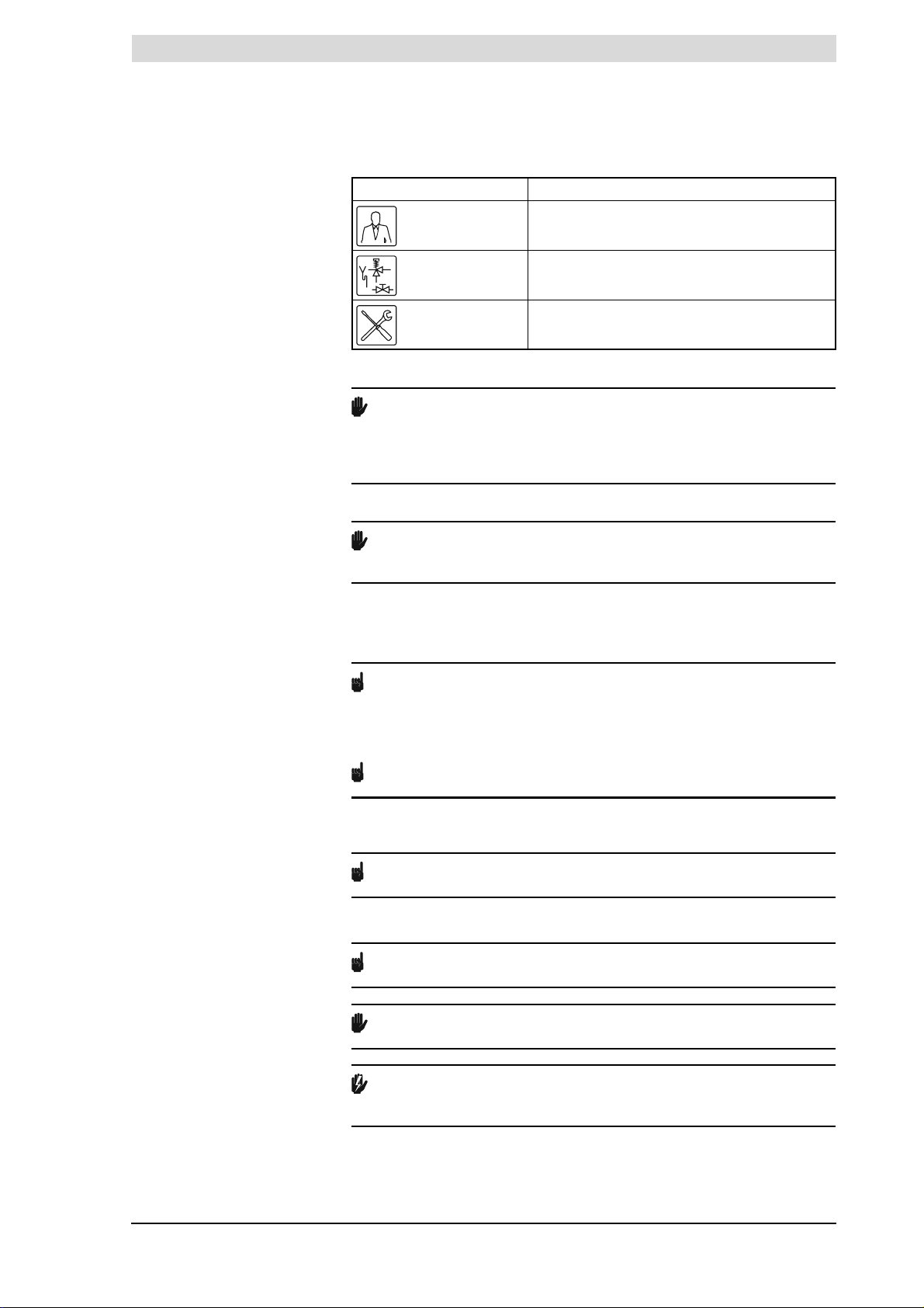
The three target groups for this manual are:
• (end) users;
• installation engineers;
• service and maintenance engineers.
Symbols on each page indicate the target groups for whom the information is
intended. See the table.
10 Instruction manual SGE
Page 14
gis
Target group symbols
Symbol Target Group
(End) user
Installation engineer
Service and maintenance engineer
Caution
This water heater is not intended for use by persons with reduced physical,
sensory or mental capacities, or who lack the necessary experience or
knowledge, unless the person responsible for their safety is supervising them or
has explained to them how the water heater should be used.
Caution
This water heater is not intended to be used by children. Always supervise
children, and ensure that they do not play with the water heater.
1.5 Maintenance
1.6 Notation
conventions
A service should be carried out at least once a year, both on the water side and
on the gas side. Among other things, the service interval depends on the water
quality, the average burning time per day and the set water temperature.
Note
To determine the correct service interval, it is recommended to arrange for
the service and maintenance engineer to check the water heater on both the
water and gas side within three months following installation. Based on this
check, the best service interval can be determined.
Note
Regular maintenance extends the service life of the water heater.
Both the end user and the service and maintenance engineer are responsible
for regular maintenance. They will need to establish clear agreements on this.
Note
If the water heater is not regularly serviced, the warranty will become void.
The following notation is used in this manual:
Note
Important information.
Caution
Ignoring this information can lead to the water heater being damaged.
Warning
Failure to carefully read this information may lead to danger of personal
injury, and serious damage to the water heater.
Instruction manual SGE 11
Page 15
1
Introduction
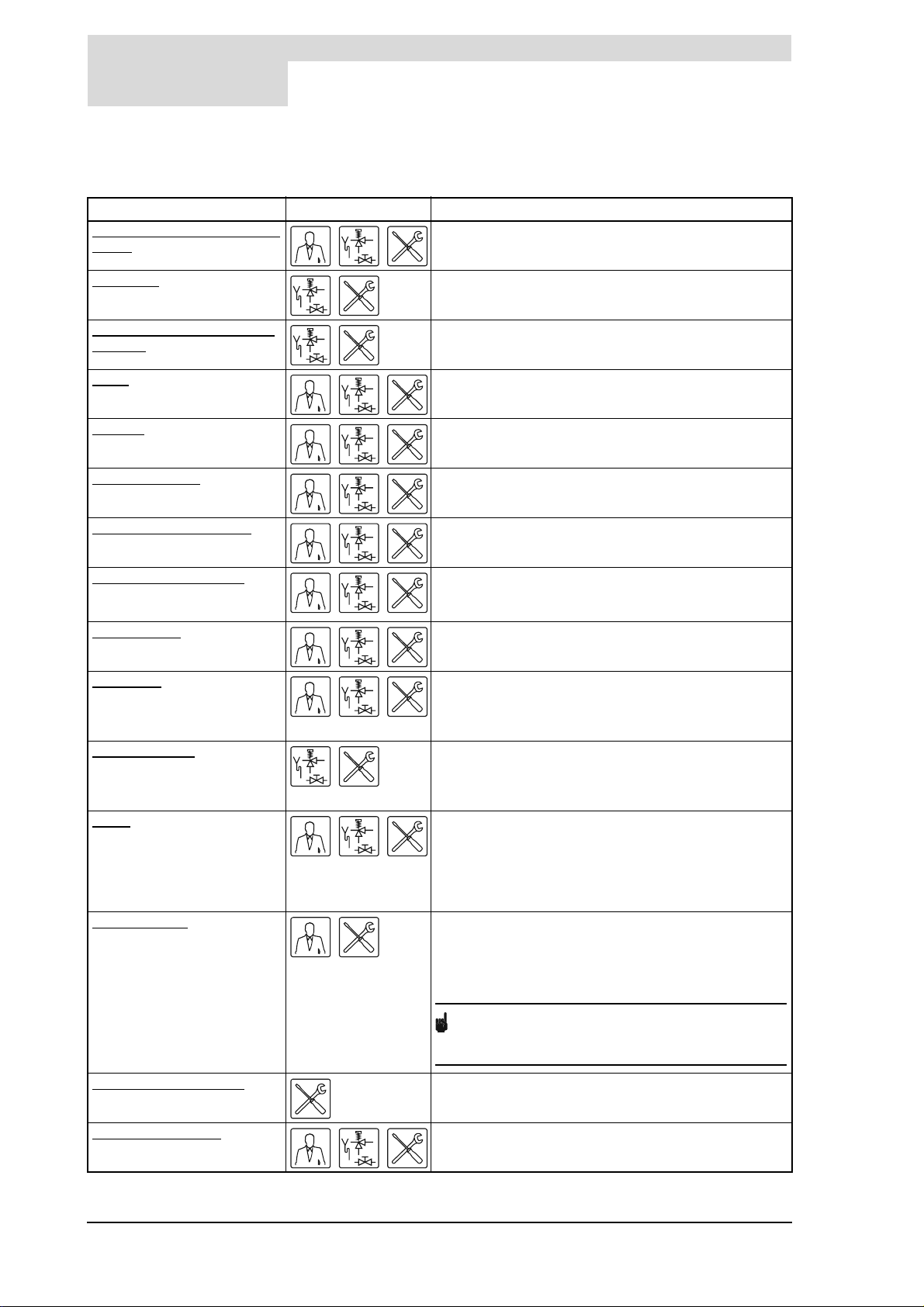
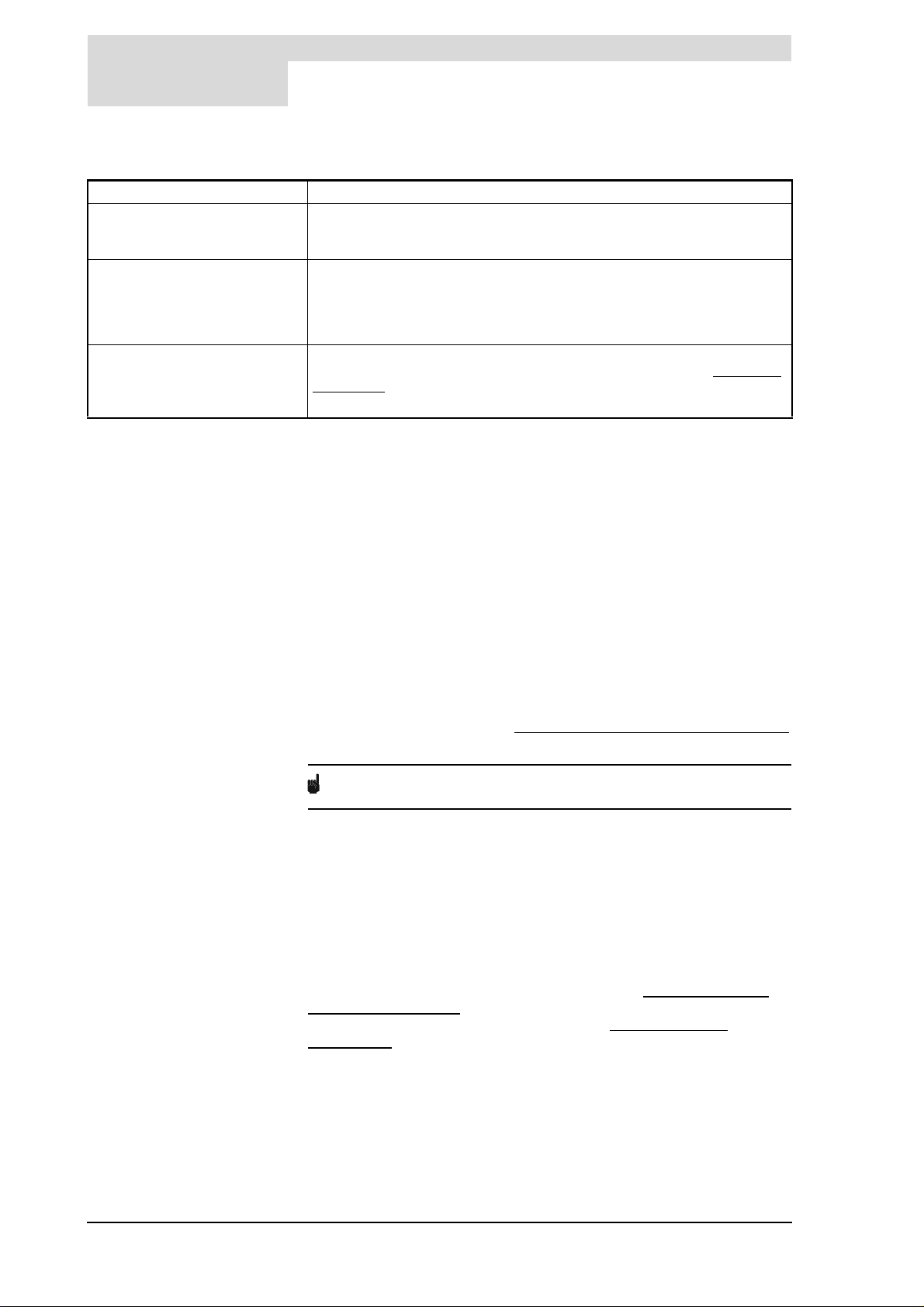
1.7 Overview of this
document
Chapter Target groups Description
Working principle of the water
heater
This chapter describes the working principle of the water
heater.
gis
Installation
Conversion to a different gas
category
Filling
Draining
The control panel
Status of the water heater
Starting the water heater
Shutting down
Main menu
Service program This chapter describes the service menu. It is mainly
Errors This chapter is mainly intended for the installation
Service interval
This chapter describes the installation activities to be
carried out before final commissioning.
This chapter describes the activities required to convert
the water heater to a different gas category.
This chapter describes how to fill the water heater.
This chapter describes how to drain the water heater.
This chapter describes the general control of the water
heater using the display.
This chapter describes the status (mode or condition) that
the water heater may have, and possible actions to take.
This chapter describes how to start the water heater. The
general operating cycle of the water heater is also
described.
This chapter describes how to decommission the water
heater for a brief or long period of time.
This chapter describes the main menu of the display. This
is the actual menu for the user. However, the installation
engineer and service and maintenance engineers will also
need to use this menu.
intended for the installation engineer and service and
maintenance engineers. End users may also refer to this
chapter for additional information about the water heater.
engineer and the service and maintenance engineer. It
describes water heater errors. These errors are reported
on the display. A troubleshooting table of possible causes
and solutions is provided. End users may also refer to this
chapter for additional information about the water heater.
This chapter describes how to determine the optimum
service interval (frequency of regular maintenance). Both
the end user and the service and maintenance engineer
are responsible for regular maintenance. They need to
reach clear agreement on this.
Note
If the water heater is not regularly serviced, the
warranty will become void.
Performing maintenance This chapter sets out the maintenance tasks to be carried
out.
Warranty (certificate)
This chapter states the warranty terms and conditions.
12 Instruction manual SGE
Page 16
gis
2 Working principle of
the water heater
2.1 Introduction
2.2 General working
principle of the water
heater
This chapter covers the following topics:
• General working principle of the water heater
• Water heater operating cycle
• Protection for the water heater;
• Safety of the installation
• Protection for the solar heating system;
• Safety of the solar heating system
The water heater is fitted with a modulating premix burner system with 1:1 gasto-air ratio regulation. The air required for combustion is delivered by the fan
(18). The gas is supplied via the gas control valve (16) and the venturi (30) on
the intake side of the fan. The 1:1 gas-to-air ratio always guarantees the most
efficient gas/air mixture.
In this water heater, the cold water enters the bottom of the tank through the cold
water inlet (14). The water is heated by means of a heat exchanger (55)
connected to a solar heating system and a gas-fired heat exchanger (11).
The heated tap water leaves the tank through the hot water outlet (2). Once the
water heater is completely filled with water, it will constantly be under mains
water pressure. As hot water is drawn from the water heater, cold water is
immediately added.
The special design of the heat exchanger (11) ensures that the flue gases are
first led downwards via the combustion chamber, then upwards via the heat
exchanger, and downwards again alongside the water in the tank. The flue
gases gradually become cooler in the process. Because the cooled flue gases
flow alongside the cold water lower down in the tank, they start to condense.
This condensation causes latent heat energy to be transferred to the cooler
water, thereby increasing the performance of the unit. The condensate yielded
by this process is discharged via the condens trap (23).
The insulation layer (24) prevents heat loss. The inside of the tank is enamelled
to protect against corrosion. The anodes (9) provide extra protection against
corrosion.
The water heater has an inspection and cleaning opening (12) for maintenance.
;
;
.
;
Instruction manual SGE 13
Page 17
2
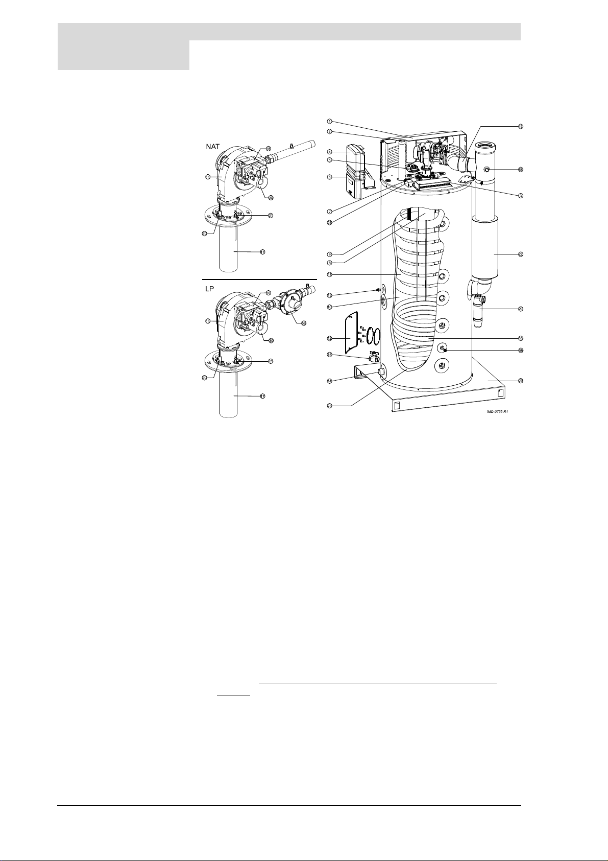
Legend
Unused numbers are not applicable
1. cover
2. hot water outlet
3. electrical connector block
4. controller
5. pressure switch
6. control panel
7. temperature sensor T
8. combustion chamber
9. anode
10. tank
11. heat exchanger
12. inspection and cleaning
opening
13. temperature sensor T
14. cold water inlet
15. drain valve
16. gas control valve
17. burner
18. fan
19. air supply hose
20. hot surface igniter
21. flame probe
22. chimney pipe
23. condens trap
24. insulation layer
29. base
55. heat exchanger (e.g. solar
heating system)
56. temperature sensor S
58. flue gas test nipple
59. pressure-reducing valve
1
2
2
Working principle of the water heater
gis
Cut-away view of the water heater
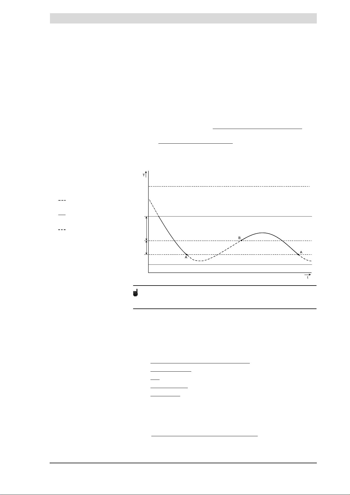
2.3 Water heater
operating cycle
The water temperature (T 1) at the top of the water heater is used to control
when the gas burner is started and stopped. The temperature changes in the
water heater are used for switching the solar heating system on and off (using
and S2). T1 is the curve shown in the figure. In addition, temperatures S1 and
T
1
are used by the solar heating system controller. Temperature S1 is
S
2
measured in the solar collector and S
exchanger (55).
The other settings that govern the control behaviour are:
•T
set
T
is the the required water temperature that has been set on the
set
appliance (11.4.1 "
MENU"). As soon as T1 falls below T
heating the water, but only if the temperature of the heating fluid (S
greater than the temperature measured at the appliance (sensor S
given (adjustable) amount. When T1 = T
heating system stops. There is one exception to this rule, which is when
T
solar limit
is set to a higher value than T
Setting the water temperature via the SET POINT
between the inlet and outlet of the heat
2
, the solar heating system starts
set
set
set
= T
.
solar limit
, heating by the solar
) is
1
) by a
2
14 Instruction manual SGE
Page 18
gis
T
solar limit
T
set
Solar diff.
Hys.
T
min = 45C
Legend
A = Gas burner on
B = Gas burner off
:
T
1
• = No heat demand, so water
is not heated
• = Water heated via solar
heating system
• = Water heated via solar
heating system and gas burner
t = time
T = Temperature
o
45
C = Minimum tap water
temperature
• Hysteresis
The moment that T1 falls below (T
set
- T
- hysteresis), the controller
solar diff
registers such a heat demand that the gas burner and the solar heating
system jointly heat the water. The solar heating system is only employed
when the temperature measured by S
than that of S
•T
solar diff
When T
.
2
exceeds (T
net
set
- T
solar diff
is heated by the solar heating system alone. When T
(provided that T
value of T
•T
solar limit
solar diff
set
= T
), the solar heating system is switched off. The
solar limit
is adjustable (12.10.4 "Setting the solar difference").
is a certain (adjustable) value grater
1
), the gas burner is shut off and the water
rises above T
1
Preset (12.10.3 "Setting the solar limit") water temperature at which heating
via the solar heating system is stopped.
Graphical representation of operating cycle
set
Note
can rise above T
T
1
. However, this is only possible if T
set
solar limit
is increased
via the service menu.
2.4 Protection for the
water heater
2.4.1 Introduction
The controller monitors the water temperature, helps ensure the safe use of the
solar heating system, and ensures safe combustion. This takes place using:
• the Water heater water temperature protection
• the Gas control valve
•the Fan
• the Pressure switch
• the Flame probe
2.4.2 Water heater water temperature protection
The controller (4) controls and monitors the safety of the water heater by means
of sensors T
and T2. S2 is also used for protection of the water heater.
1
However, this is primarily intended for control of the solar heating
system (2.6 "Protection for the solar heating system").
The table explains the functioning of these temperature sensors.
Instruction manual SGE 15
Page 19
2
protection Description
Against frost:
< 5°C
- T
1
< 5°C
- T
2
Against overheating of water:
> 88°C
- T
1
> 88°C
- T
2
- S2 > 88°C
For extra safety:
> 93°C
- T
1
> 93°C
- T
2
> 93°C
- S
2
Working principle of the water heater
Temperature protection
The frost protection cuts in. The water is heated to 20°C.
The high-limit safeguard serves to prevent overheating and/or excessive
formation of scale in the water heater. If the high-limit safeguard is activated,
the heating is stopped. This causes the water in the tank to cool down. Once
the water has cooled sufficiently (T1 < 81°C), the controller resets the water
heater.
A lockout error of the water heater controller takes place. The controller must
be manually reset before the water heater can resume operation (8.3 "
conditions"). The reset may only be performed once T 1 <81°C.
2.4.3 Gas control valve
The controller opens the gas control valve so that gas can be supplied to the
burner. As a safety measure, the gas control valve has two valves. Both valves
shut off the gas supply.
2.4.4 Fan
The fan (18) provides an optimum air supply when there is a heat demand. As
a safety feature, the fan ensures that any gases present in the combustion
chamber are removed, both before and after combustion. We refer to this as
pre- and post-purge.
The fan speed is continuously monitored by the controller (4). The controller
takes control if the fan rpm varies too much from the value set.
gis
Error
2.5 Safety of the
installation
2.4.5 Pressure switch
The pressure switch only guarantees the supply of air during pre-purging of the
water heater. If the pressure difference during pre-purging is sufficient, the
pressure switch closes. The table (3.4.2 "General and electrical specifications")
shows the trip point for each water heater.
Note
The trip point of the pressure switch is not adjustable.
2.4.6 Flame probe
To ensure that no gas can flow when there is no combustion, the water heater
is fitted with a flame probe (21). The controller uses this probe to detect the
presence of a flame, by means of ionisation detection. The controller closes the
gas control valve the instant it detects that there is a gas flow but no flame.
Excessive pressure in the tank can damage the enamelled layer (in the water
heater) or the tank itself. An inlet combination and pressure-reducing valve
prevents this. The inlet combination acts as a stop valve, non-return valve and
overflow valve. If the water mains pressure is too high (3.4.2 "
electrical specifications"), a pressure-reducing valve must be used. Both
components must be fitted in the cold water inlet (3.7 "Vented water
connections").
The use of an expansion vessel, expansion valve and/or pressure reducing
valve depends on the type of installation: unvented or vented.
General and
16 Instruction manual SGE
Page 20
gis
2.5.1 Unvented installation
With an unvented installation, an expansion valve and expansion vessel prevent
the buildup of excessive pressure in the tank. This prevents damage being
caused to the enamel coating (in the water heater) or to the tank. A non-return
valve prevents excessive pressure build-up in the water supply system. This
valve also prevents water from flowing backwards from the tank into the cold
water supply system. The pressure-reducing valve protects the water heater
against excess mains water pressure (3.4.2 "
specifications"). These components are installed in the cold water
inlet (3.7 "Vented water connections").
2.5.2 Vented installation
With a vented installation, excess pressure is taken up by the open cold water
head tank. The level of the cold water head tank determines the maximum
working pressure (3.4.2 "
water heater must also be fitted with a vent pipe from the hot water pipe, which
opens into the cold water head tank.
Ideally, the vent pipe should discharge into a separate discharge channel/drain
or otherwise to the open cold water head tank. The water heater should also be
fitted with a stop valve (3.6.2 "Hot water side") on the hot water side.
2.5.3 T&P valve
A T&P valve is only mandatory in unvented installations. However, A.O.Smith
also recommends the use of a T&P valve in vented installations.
A T&P (Temperature and Pressure Relief) valve monitors the pressure in the
tank and the water temperature at the top of the tank. If the pressure in the tank
becomes too high (3.4.2 "General and electrical specifications"), the valve will
open. The hot water can now flow out of the tank. Because the water heater is
under water supply pressure, cold water will automatically flow into the tank.
The valve remains open until the unsafe situation has been rectified. The water
heater is fitted standard with a connection for a T&P valve (3.6.2 "
side").
General and electrical
General and electrical specifications") in the tank. The
Hot water
2.6 Protection for the
solar heating system
2.6.1 Drain-back tank
2.6.2 Fluid temperature
The solar heating system may optionally be equipped with a drain-back tank.
The tank fills itself with the heating fluid when there is no heat demand. This
avoids overheating of the solar heating system. The high insulation factor of the
tank also protects the system against freezing of the fluid. The use of the drainback tank also serves to extend the useful life of the fluid.
The existence of a drain-back tank is set (12.10.1 "
during the installation. Refer to the solar heating system manual for more
details.
The heat exchanger of the solar heating system is filled with glycol. If the
temperature of the heating fluid is too high, a signal is sent to the controller of
the solar collector and the pump of the solar collector is switched off. This signal
is passed to the controller by temperature sensor S
Setting the drain-back tank")
.
1
Instruction manual SGE 17
Page 21
2
2.7 Safety of the solar
heating system
2.7.1 Expansion vessel
2.7.2 Expansion valve
Working principle of the water heater
gis
Temperature protection for solar heating system
Protection Description
Maximum temperature:
> 130°C
- S
1
The solar heating system must be equipped with an expansion vessel. An
expansion vessel serves to limit pressure variations in the system. The
expansion vessel in the solar heating system can withstand a maximum
pressure of 600 kPa (6 bar). The supply pressure to the expansion vessel
depends on the static head of the system.
The system is protected from overpressure by an expansion
valve (2.7.1 "
The solar heating system is equipped with an expansion valve. The expansion
valve monitors the pressure in the solar heating system. Should the pressure
become higher than 600 kPa (6 bar), the valve will open. The hot water can now
flow out of the installation. The valve remains open until the unsafe situation has
passed, i.e. until the pressure has fallen back to below 600 kPa (6 bar).
Expansion vessel") as well as the expansion vessel.
The pump of the solar heating system switches off
when the temperature of the heating fluid at S1
exceeds the maximum value. The solar heating
system enters error mode. The error is also visible
on the display of the SGE water heater
Note
Because a closed system is pressurized and is not filled automatically, the
system will have to be filled (5 "
been activated. A system with a drain-back tank is not pressurized and does not
have an expansion valve.
Filling") again when the expansion valve has
18 Instruction manual SGE
Page 22
is
3 Installation
Warning
The installation must be carried out by an approved installation engineer in
compliance with the general and local regulations imposed by the gas, water
and power supply companies and the fire brigade.
The appliance may only be installed in a room that complies with the
requirements stated in national and local ventilation
regulations (1.3 "Regulations").
3.1 Introduction
3.2 Packaging
This chapter describes the installation activities to be carried out before final
commissioning (9 "
• Packaging
• Ambient conditions
• Technical specifications;
• Installation diagram
• Unvented water connections
• Vented water connections;
• Gas connection
• Air supply and chimney flue discharge
• Solar heating system;
• Electrically connecting the water heater
• Electrical connection of the solar heating system;
• Check the supply pressure, gas control valve pressure, CO
switching pressure.
For possible conversion to a different gas category, see
conversion (4 "Conversion to a different gas category").
To avoid damaging the water heater, remove the packaging carefully.
We recommend unpacking the water heater at or near its intended location.
Caution
The water heater may only be manoeuvred in an upright position. Take care
that the water heater is not damaged after unpacking.
Starting the water heater"), namely:
;
;
;
;
;
;
;
value and
2
3.3 Ambient conditions
The water heater is suitable for either open or room-sealed combustion. If
installed as a room-sealed water heater, it is independent of the installation
site for the necessary external air supply. In this event, there are no additional
ventilation requirements.
If the water heater is to be installed as an open system, it must meet the
locally-applicable directives and ventilation regulations for open water
heaters.
The possible installation types are B23, C13, C33, C43, C53 and C63.
Caution
The water heater may not be used in rooms where chemical substances are
stored or used due to the risk of explosion, and corrosion of the water heater.
Some propellants, bleaching agents and degreasing agents etc. disperse
vapours that are explosive and/or cause accelerated corrosion. If the water
heater is used in a room in which such substances are present, the warranty will
be void.
Instruction manual SGE 19
Page 23
3
Installation
3.3.1 Air humidity and ambient temperature
The boiler room must be frost-free, or be protected against frost. The table
shows the ambient conditions that must be adhered to for correct functioning of
the electronics present in the appliance to be guaranteed.
Air humidity and ambient temperature specifications
Air humidity and ambient temperature
Air humidity max. 93% RH at +25°C
Ambient temperature functionality: 0 <
3.3.2 Water heater maximum floor load
Allow for the water heater's weight and the maximum floor load; refer to the
table (3.4.2 "
3.3.3 Water composition
The appliance is intended for heating drinking water. The drinking water must
comply with the regulations governing drinking water for human consumption.
The table gives an overview of the specifications.
Water specifications
General and electrical specifications").
is
T < 60°C
Water composition
Hardness
(alkaline earth ions)
Conductivity > 125 µS/cm
Acidity (pH value) 7.0 < pH value < 9.5
Note
If the water specifications deviate from those stated in the table, then the
tank protection cannot be guaranteed (16 "Warranty (certificate)").
3.3.4 Working clearances
For access to the water heater, it is recommended that the following
clearances are observed (see figure):
• AA: around the water heater's control column and cleaning openings: 100
cm.
• BB: all sides of the water heater: 50 cm.
• Top of the water heater: 100 cm
> 1.00 mmol/l:
• German hardness> 5.6° dH
• French hardness > 10.0° fH
• English hardness > 7.0° eH
•CaCO
> 100 mg/l
3
20 Instruction manual SGE
Page 24
is
IMD-0767 R0
A
A
AA
B
B
IMD-0772 R0
3
5
5
P
M
6
11
1
4
R
Z
S
K
N
A
4
D
G
2
2
3
6
H
U
T
W
Y
V
X
F
Hy
C
E
Ny
45º
45º
44º
7
10
9
13
14
12
Hx
Working clearances
3.4 Technical
specifications
The water heater is supplied without accessories. Check the
dimensions (3.4 "
Technical specifications"), gas data (3.4.3 "Gas data") and
other specifications (3.4.2 "General and electrical specifications") of any
accessories you plan to use.
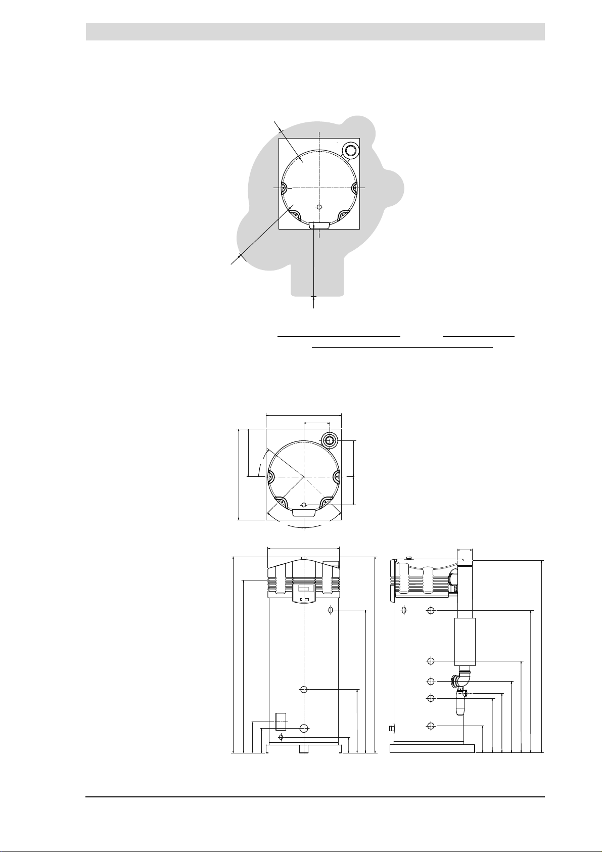
3.4.1 Dimensions of the water heater
Plan and elevation of the water heater
Legend
See the table.
Instruction manual SGE 21
Page 25
3
Installation
is
Size Description Unit SGE 40 SGE 60
A Overall height mm 2055 2055
C Position on pallet mm 490 490
D Appliance diameter mm 705 705
E Depth mm 925 925
F Width mm 850 850
G Diameter of flue gas discharge mm 100 / 150 100 / 150
H Height of chimney flue mm 1995 1995
Hx x position flue gas outlet mm 260 260
Hy x position flue gas outlet mm 370 370
K Height of gas/burner connection mm 1960 1960
M Height of cold water supply mm 185 185
N Height of hot water outlet mm 2055 2055
Ny y position of hot water outlet mm 205 205
P Height of cleaning opening mm 365 365
R Height of drain valve connection mm 180 180
S Height of T&P valve connection mm 1555 1555
T Height of coil inlet mm 630 630
U Height of coil outlet mm 305 305
V Height of recirculation connection mm 1035 1035
W Height of condensation drain mm 765 765
X Height of heat exchanger supply mm 1465 1465
Y Height of heat exchanger discharge mm 855 855
Z Height of electric element connection mm 755 755
1
1 Cold water supply connection (external) - R 1
2 Hot water outlet (male) - R 11/
3 Gas control valve connection (external) - R 3/
4 Drain valve connection (internal) -
5 T&P valve connection (female) - 1" - 11.5 NPT 1" - 11.5 NPT
6 Cleaning/inspection opening mm 95 x 70 95 x 70
7 Condensation drainage connection (female) - Ø 40 Ø 40
9 Coil inlet connection (female) - Rp 1 Rp 1
10 Coil outlet connection (female) - Rp 1 Rp 1
11 Electric element connection (female) - Rp 1
12 Heat exchanger supply connector (female) - Rp 1 Rp 1
13 Heat exchanger outlet connector (female) - Rp 1 Rp 1
14 Recirculation connection (female) - Rp 1 Rp 1
/
2
2
4
3
/4"
1
/
2
R 11/
R 11/
R 3/
4
3
/4"
Rp 11/
2
2
2
22 Instruction manual SGE
Page 26
is
3.4.2 General and electrical specifications
General and electrical specifications
Description Unit SGE 40 SGE 60
Contents litres 370 370
Empty weight kg 245 245
Maximum floor load kg 615 615
Maximum operating pressure (vented) kPa (bar) 800 (8) 800 (8)
Maximum operating pressure, unvented kPa (bar) 550 (5,5) 550 (5,5)
Control thermostat adjustment range °C 40…80 40…80
Control thermostat and default value °C 65 65
Adjustment range for hysteresis downwards °C 2…12 2…12
Default value for hysteresis downwards °C 5 5
Adjustment range for solar differential °C 0…8 0…8
Solar differential default value °C 3 5
Adjustment range for solar limit °C 65…80 65…80
Solar limit default value °C 65 65
Number of (electrical) anodes - 2 2
Observed pressure differential across the pressure switch Pa >
Pressure differential to open the pressure switch Pa <
Heating time ΔT = 45°C at least 15 11
165 > 165
115 < 115
Description Unit SGE 40 SGE 60
Electrical power consumption of the appliance W 60 120
Electrical power consumption of the solar controller W max. 700 max. 700
Supply voltage (-15% +10% V
Mains frequency (+
IP class - IP 20 IP 20
Description Unit Value
Maximum mains pressure of cold water supply (vented) kPa (bar) 800 (8)
Maximum mains pressure of cold water supply (unvented) kPa (bar) 500 (5,5)
Maximum mains pressure of the protected cold supply setup kPa (bar) 500 (5)
T&P overflow pressure kPa (bar) 700 (7)
T&P overflow temperature °C 97
1Hz) Hz 50 50
AC) volts 230 230
Instruction manual SGE 23
Page 27
3
Installation
is
3.4.3 Gas data
Gas data
II
description Unit SGE 40 SGE 60
2H3P
Gas category 2H: G20 - 20 mbar
Venturi injector diameter mm - -
Nominal load (gross) kW 44,4 63,3
Nominal output kW 42,8 60,4
Supply pressure mbar 20 20
(full load) Vol% 9,0 + 1,0 9,0 + 1,0
CO
2
Gas consumption
Gas category 3P: G31 - 37/50 mbar
Venturi injector diameter mm 6,00 6,00
Nominal load (gross) kW 43,5 62,0
Nominal output kW 42,8 60,4
Supply pressure mbar 37 / 50 37 / 50
Gas control valve pressure mbar 12,0 +
(full load) Vol% 10,0 + 1,0 10,0 + 1,0
CO
2
Gas consumption
(*) Based on 1013.25 mbar and 15°C.
(*)
(*)
m3/h 4,2 6,0
2,0 12,0 + 2,0
kg/h 3,1 4,4
24 Instruction manual SGE
Page 28
is
IMD-0783 R0
VENTED
UNVENTED
A
4
19
18
E
H
17
9
9
GGF
F
C
C
BBS
2
S
2
S1S
1
37
37
11
11
12
12
T
T
26
26
42
42
14
14
14
14
14
14
3
3
D
D
10
10
13
13
Q
T
665
5
4
4
4
4
S
4
S
4
A45115
16
161638
38
4
Q
T
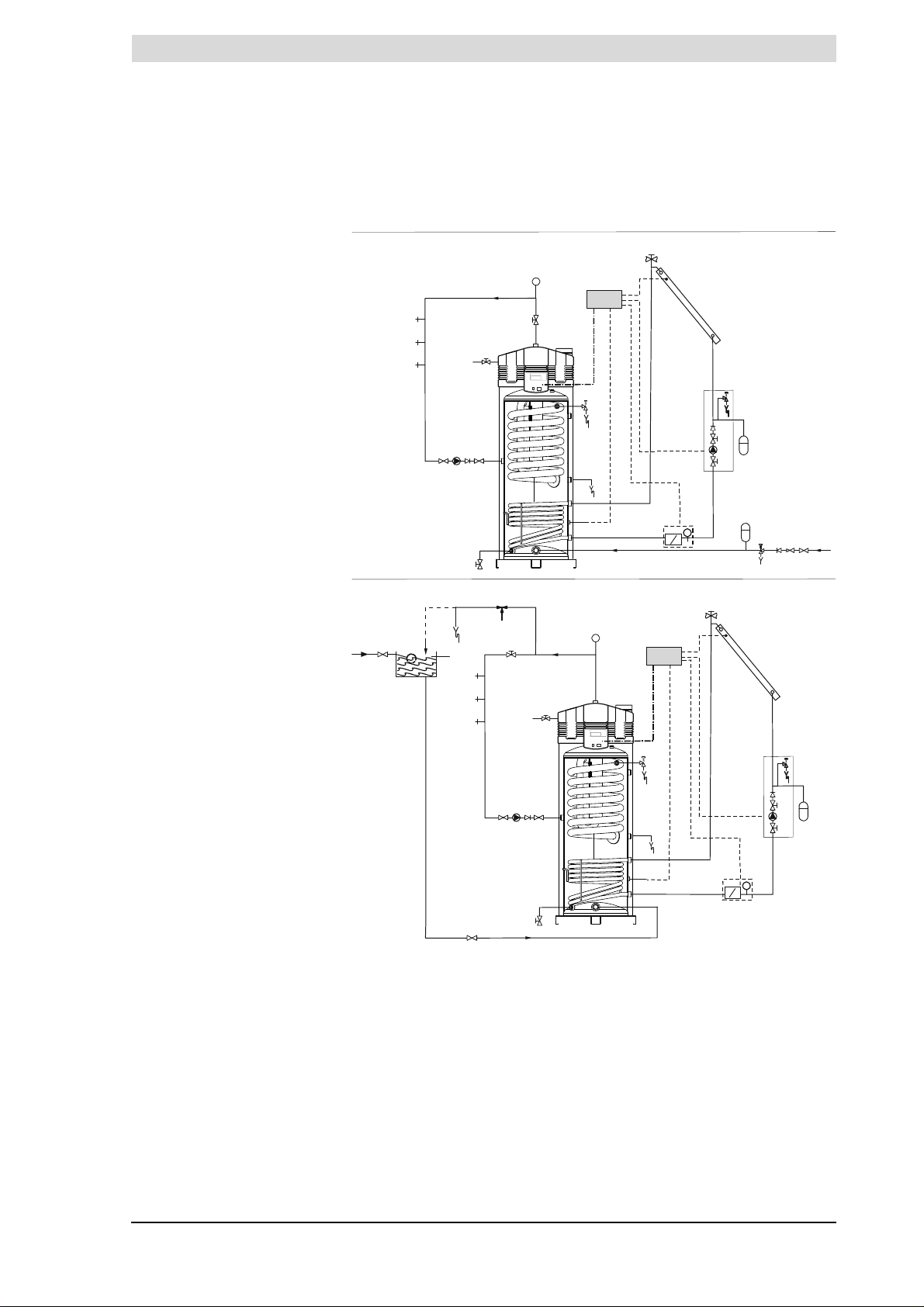
3.5 Installation diagram
The figure shows the Installation diagram. This diagram is referred to in the
sections describing the actual connection procedure.
Installation diagram
Legend Vented and unvented
Unused numbers are not applicable
1. pressure reducing valve
(mandatory)
3. T&P valve (mandatory)
4. stop valve (recommended in
pipe C and mandatory in pipe
A)
5. non-return valve (mandatory)
6. circulation pump (optional)
9. drain valve (mandatory)
10. manual gas valve
(mandatory)
20. pressure valve (mandatory)
26. air bleed (mandatory)
11. service stop valve
(recommended)
12. temperature gauge
(recommended)
13. condensation drain
(mandatory)
14. draw-off points
15. expansion valve (mandatory)
16. expansion vessel
17. 3-way aeration valve
(mandatory)
(recommended)
18. cold water head tank
19. float switch
23. pressure valve (mandatory)
37. combined Q/T sensor
(optional)
38. solar heating system pump
station (modulating mandatory)
A. cold water supply
B. hot water supply
C. circulation pipe
D. gas supply
E. overflow pipe
F. supply heat exchanger
G. heat exchanger return
H. overflow protection
. collector sensor (mandatory)
S
1
S
. tank sensor (mandatory)
2
S4. heat exchanger discharge
sensor (optional)
Instruction manual SGE 25
Page 29
3
Installation
is
Caution
The installation diagram shows a pump station with an integrated non-return
valve. This type of pump unit may only be used with closed systems. In systems
with drain-back, installation of a pump unit with non-return valve is prohibited.
There are special pump units for these systems. Please contact the pump unit
supplier for this.
3.6 Unvented water
connections
Warning
The installation should be carried out by a competent person, in compliance
with general and locally applicable regulations (1.3 "Regulations").
3.6.1 Cold water side
See (A) in the installation diagram (3.5 "Installation diagram").
1. Fit an approved stop valve (4) on the cold water side as required by the
applicable regulations (1.3 "
2. The maximum working pressure of the water heater is 8 bar. Because the
pressure in the water pipe at times can exceed 8 bar, you must fit an
approved pressure-reducing valve (1).
3. Fit a non-return valve (5) and an expansion vessel (16).
4. Fit an expansion valve (15) and connect the overflow side to an open waste
water pipe.
3.6.2 Hot water side
See (B) in the installation diagram (3.5 "Installation diagram").
Note
Insulating long hot water pipes prevents unnecessary energy loss.
1. Optional: fit a temperature gauge (12) so you can check the temperature of
the tap water.
2. Fit the T&P valve (3).
3. Fit a stop valve (11) in the hot water outlet pipe for servicing.
Regulations").
3.6.3 Circulation pipe
See (C) in the installation diagram (3.5 "Installation diagram").
If an immediate flow of hot water is required at draw-off points, a circulation
pump can be installed. This improves comfort, and reduces water wastage.
1. Fit a circulation pump (6) of the correct capacity for the length and resistance
of the circulation system.
2. Fit a non-return valve (5) after the circulation pump to guarantee the
direction of circulation.
3. Fit two stop valves for servicing (4).
4. Connect the circulation pipe according to the installation
diagram (3.5 "
3.6.4 Condensation drain
1. Fit a sloping waste water pipe to the condens trap (13) for condensation
drainage and connect this via an open connection to the waste water
discharge.
Caution
If the condensation drain is not fitted to the waste water discharge using an
open connection, this can cause faults.
26 Instruction manual SGE
Installation diagram").
Page 30
is
3.7 Vented water
connections
Warning
The installation should be carried out by a competent person, in compliance
with general and locally applicable regulations (1.3 "Regulations").
3.7.1 Cold water side
See (A) in the installation diagram (3.5 "Installation diagram").
1. Fit an approved stop valve (4) on the cold water side between the cold water
head tank (18) and the water heater, as required by applicable regulations.
3.7.2 Hot water side
See (B) in the installation diagram (3.5 "Installation diagram").
Note
Insulating long hot water pipes prevents unnecessary energy loss.
1. Fit the T&P valve (3).
2. Optional: fit a temperature gauge (12) so you can check the temperature of
the tap water.
3. Fit a stop valve (4) in the hot water outlet pipe for servicing.
4. If a circulation pipe is required, continue by installing the circulation
pipe (3.6.3 "
Circulation pipe").
3.7.3 Circulation pipe
See (C) in the installation diagram (3.5 "Installation diagram").
If an immediate flow of hot water is required at draw-off points, a circulation
pump can be installed. This improves comfort, and reduces water wastage.
1. Fit a circulation pump (6) of the correct capacity for the length and resistance
of the circulation system.
2. Fit a non-return valve (5) after the circulation pump to guarantee the
direction of circulation.
3. Fit two stop valves for servicing (4).
4. Connect the circulation pipe according to the installation
diagram (3.5 "
Installation diagram").
3.7.4 Condensation drain
1. Fit a sloping waste water pipe to the condens trap (13) for condensation
drainage and connect this via an open connection to the waste water
discharge.
Caution
If the condensation drain is not fitted to the waste water discharge using an
open connection, this can cause faults.
Instruction manual SGE 27
Page 31

3
Installation
is
3.8 Gas connection
3.9 Solar heating system
Warning
The installation should be carried out by a competent person, in compliance
with general and locally applicable regulations (1.3 "Regulations").
Caution
Make sure that the diameter and length of the gas supply pipe are large
enough to supply sufficient capacity to the water heater.
See (D) in the installation diagram (3.5 "Installation diagram").
1. Fit a manual gas valve (10) in the gas supply pipe.
2. Blow the gas pipe clean before use.
3. Close the manual gas valve.
4. Fit the gas supply pipe to the gas control valve.
Warning
After fitting, check for leaks.
Note
Please refer to the installation diagram (3.5 "
diagram (17.4 "
block (3.12.1 "Preparation") for details of how to connect the solar heating
system.
1. Connect the supply from the solar collector to the inlet (F) of the heat
exchanger.
2. Connect the return pipe to the solar collector to the outlet (G) of the heat
exchanger.
3. Connect the lead to the solar heating system controller and sensor S
- electrical diagram (17.4 "
and
- connections table (3.11.2 "Preparation").
4. Connect the communication cable between the solar heating system
controller and the water heater, see:
- electrical diagram (17.4 "
and
- connections table (3.11.2 "Preparation").
Electrical diagram, solar heating system") and terminal
Electrical diagram, solar heating system")
Electrical diagram, solar heating system")
Installation diagram"), electrical
, see:
2
Warning
The installation diagram shows a pump station with an integrated non-return
valve. This type of pump unit may only be used with closed systems. In systems
with drain-back, installation of a pump unit with non-return valve is prohibited.
There are special pump units for these systems. Please contact the pump unit
supplier for this.
28 Instruction manual SGE
Page 32

is
3.10 Air supply and
chimney flue
discharge
3.10.1 Introduction
This section covers the following topics:
• Requirements for flue gas discharge materials
• Concentric connections
• Parallel connections
3.10.2 Requirements for flue gas discharge materials
Warning
The installation should be carried out by a competent person, in compliance
with general and locally applicable regulations (1.3 "Regulations").
Depending on the approved installation types, there are several alternatives for
connecting the air supply and chimney flue.
The water heaters are approved for installations of type B23, C13, C33, C43,
C53 and C63.
This manual discusses installation types C13 and C33 in detail. If the water
heater has to function in accordance with B23, C43, C53 or C63, you can obtain
more information by contacting A.O. Smith.
The figure and table give information about these types of installation. For an
explanation of the possibilities, please contact the manufacturer.
Instruction manual SGE 29
Page 33

3
IMD-0789 R0
C43
C13 C53
B23 C33
Installation
is
Installation types
30 Instruction manual SGE
Page 34

is
Explanation of types of installation
Installation type Description
B23 Air for combustion is drawn from the boiler room.
C13 Concentric and/or parallel wall flue terminal.
C33 Concentric and / or parallel roof flue terminal
C43 Water heaters on common air supply and flue gas discharge (concentric
C53 Air supply and flue gas discharge terminal types mixed.
C63 Water heaters supplied without flue gas discharge materials and/or terminal.
3.10.3 Concentric connections
and/or parallel) in multi-storey building.
These water heaters must be installed in compliance with local regulations.
Note
Make sure that the chimney flue discharges into an area approved for this
type of installation.
The table shows the requirements for concentric systems.
Warning
Install flue gas discharge pipe runs with a run-off of 5 mm per metre towards
the water heater.
Flue gas discharge requirements for concentric systems (C13, C33)
Appliance Diameter Maximum length Maximum
number of 90
bends
SGE 40 100/150 mm 40 m 7
SGE 60 100/150 mm 40 m 7
Caution
Both conditions stated in the table must be fulfilled.
Even if you use less than the stated maximum number of bends, the maximum
pipe length still may not be exceeded.
Even if you use less than the stated maximum pipe length, the maximum
number of bends still may not be exceeded.
The following example illustrates how to use the table.
o
Practical example of concentric flue gas discharge
Example
The figure shows a SGE 60 installation. The water heater must be fitted with 10
m of concentric pipe (C13/C33) and four 90 degree bends. The configuration
must be checked for compliance with the requirements stated in the table.
Instruction manual SGE 31
Page 35

3
Installation
is
Water heater with concentric flue gas discharge material
IMD-0791 R0
According to the table, the maximum permitted length is 40 metres, and 4 x 90
degree bends are permitted. Both requirements are fulfilled.
Specifications
Caution
For type C13 and C33 installations,A.O.Smith prescribes the use of a roof
or wall flue terminal, exclusively of a type approved for the water heater. Use of
an incorrect roof or wall-mounted flue terminal can cause the installation to
malfunction.
Concentric wall flue terminal specifications C13
Subject Description
Wall flue terminal set:
• 1x wall flue terminal (incl. wall
flange & clamping ring)
• 1x pipe 500 mm
• 1x bend, 90°
Pipe material Construction Concentric
Pipe diameters Flue gas discharge Ø 100 mm
No other wall flue terminal is permitted. Use this item number to order the wall conduit set from supplier,
(1)
manufacturer or wholesaler.
Art. No. 0302 504
Construction Concentric
Manufacturer Muelink & Grol
Model M2000 MDV SEC
Flue gas discharge Thick-walled aluminium with lip ring seal
Air supply Thin-walled galvanised sheet steel
Air supply Ø 150 mm
1
32 Instruction manual SGE
Page 36

is
Concentric roof flue terminal specifications C33
Subject Description
Roof flue terminal set:
• 1x roof flue terminal
(incl. clamping ring)
• 1x pipe 1000 mm
• 1x mounting flange
Pipe material Construction Concentric
Pipe diameters Flue gas discharge Ø 100 mm
No other roof flue terminal may be used. Use this item number to order the roof flue terminal set from the
(1)
supplier, manufacturer or wholesalor.
Art. No. 0304 423
Construction Concentric
Manufacturer Muelink & Grol
Model M2000 DDV HR-C
Flue gas discharge Thick-walled aluminium with lip ring seal
Air supply Thin-walled galvanised sheet steel
Air supply Ø 150 mm
3.10.4 Parallel connections
The table states the maximum pipe lengths for parallel systems. The maximum
pipe length depends on the chosen diameter.
Warning
Install flue gas discharge pipe runs with a run-off of 5 mm per metre towards
the water heater.
1
Chimney flue requirements for parallel systems
Appliance Diameter1Maximum
total
length
SGE 40 100 55 m 4.6 m 1.2 m
SGE 60 100 55 m 4.6 m 1.2 m
SGE 40 130 100 m 2.4 m 1.4 m
SGE 60 130 100 m 2.4 m 1.4 m
1) Parallel systems with diameter of 100 mm. If the maximum total length when
using a diameter of 130 mm is insufficient, a diameter of 150 mm must be
used. Any diameter enlargement must be carried out on both air supply and
flue gas outlet.
You must use the longest pipe when calculating the pipe length. For example, if
the chimney pipe is 4 metres and the air supply pipe is 3 metres, use 4 metres
as the length for the calculation. Next, add the L
bend to this 4 metres, in both the air supply and flue gas outlet. The following
practical example illustrates how to use the table.
L
90o bend
equivalent
equivalent
for every 90° and 45°
L
equivalent
45o bend
Practical example of parallel flue gas discharge
Example
The figure shows a SGE 60 installation. This has to be fitted with a 4 m parallel
pipe 100 mm in diameter, plus four 90-degree bends. The configuration must be
checked for compliance with the requirements stated in the table.
Instruction manual SGE 33
Page 37

3
Installation
is
Appliance with parallel flue gas discharge material
The longest pipe must be used to check the maximum length. In this case, the
chimney pipe is the longest. This is 4 metres. This 4 metres is the sum of pipe
sections 1 and 2. The length of the transition piece can be ignored. The total
number of bends used in the chimney flue and air supply , is 4. The bend in the
transition piece can be ignored. According to the table, 4.6 metres must be
added for each bend. This brings the total pipe length to:
(4.6 x 4) + 4 = 18.4 + 4 = 22.4 m.
This is less than the maximum length of 55 metres stated in the table. The
installation therefore meets the requirements.
3.11 Electrically
connecting the water
heater
Warning
The installation should be carried out by a competent person, in compliance
with general and locally applicable regulations (1.3 "Regulations").
3.11.1 Introduction
This section covers the following topics:
• Preparation
• Connecting the mains power
Optionally, it is possible to connect an isolating transformer, a programcontrolled pump (a pump between the storage tank and the water heater) and
an extra alarm signal to the water heater. For these options, see:
• Isolating transformer
• Connecting a program-controlled pump
• Connecting an extra ON mode switch
• Connect additional error signal
Connecting the solar heating system is also described:
• Connecting communication cable to solar heating system
Note
The optional components are not included in the electrical power
consumption rating stated in the table (3.4.2 "
specifications").
General and electrical
34 Instruction manual SGE
Page 38

is
Legend
A. screws
B. cover
C. terminal block
3.11.2 Preparation
Caution
The water heater is phase-sensitive. It is absolutely essential to connect
the mains live (L) to the live of the water heater, and the mains neutral (N) to the
neutral of the water heater.
Caution
There must be no potential difference between neutral (N) and earth ( ).
If this is the case, then an isolating transformer (3.11.4 "
must be used in the supply circuit.
For more information or to order this isolating transformer, please contact
A.O.Smith Water Products Company.
The figure shows a view of the terminal block, and the table explains the
relevant connections.
Connector block
Isolating transformer")
In preparation, you must first remove the two covers, and the cover of the
electrical section.
1. Undo the screws of the covers.
2. Carefully remove the covers from the water heater.
The electrical section is now visible.
3. Loosen the 2 screws (A) and remove the cover (B) from the electrical
section.
The connector block (C) is now visible.
Note
Consult the table for the connections and consult the electrical diagram for
the electrical component connections.
Instruction manual SGE 35
Page 39

3
Installation
is
Terminal block
Mains
voltage
NL NL
12345678910111213141516 to 2021222324
Isolating transformer Alarm Out Program-
primary secondary
1
NL
2
X1X
2
controlled
pump
NL
3
External
ON/OFF
X3X4X5X
Bus-link
6
3.11.3 Connecting the mains power
The water heater is supplied without a power cable and isolator.
Note
In order to receive electrical power, the water heater has to be connected to
the mains power by means of a permanent electrical connection. A double-pole
isolator with a contact gap of at least 3 mm must be fitted between this
permanent connection and the water heater. The power cable must have cores
of at least 3 x 1.0 mm 2 .
Warning
Leave the water heater electrically isolated until you are ready to
commission it.
1. Connect neutral (N), live (L) and earth ( ) of the power cable to
terminals 1 thru 3 of the terminal block as shown in the
table (3.11.2 "Preparation").
2. Fit the power cable in the strain relief.
3. Connect the power cable to the isolator.
4. If you have no more connections to make:
- Fit the cover on the terminal block.
- Fit the covers onto the water heater.
3.11.4 Isolating transformer
An isolating transformer should be used if there is a case of 'floating neutral'.
Note
The total power consumed by the appliance goes via the isolating
transformer.
1. Refer to the fitting instructions provided with the isolating transformer.
(Contact the supplier for details of the correct isolating transformer.)
2. Connect the neutral (N), live (L) and earth ( ) of the power cables to
terminals 4 through 9 of the connection block according to the
table (3.11.2 "
3. Fit the cables in the strain relief.
4. If you have no more connections to make:
- Fit the cover on the terminal block.
- Fit the covers onto the water heater.
5. Connect the power cable to the isolator.
Preparation").
36 Instruction manual SGE
Page 40

is
3.11.5 Connecting a program-controlled pump
Note
The maximum power capacity for a pump regulated by the controller
is 100W.
1. Connect neutral (N), live (L) and earth ( ) to terminals 13, 14 and 15 as
indicated in the table (3.11.2 "Preparation").
2. Fit the cable in the strain relief.
3. If you have no more connections to make:
- Fit the cover on the terminal block.
- Fit the covers onto the water heater.
3.11.6 Connecting an extra ON mode switch
External ON/OFF is an option for connecting an external ON/OFF switch. In
the OFF position, the programmed operating mode is active. In the ON
position, the programmed operating mode is overruled, and "ON mode" is
active.
1. Connect leads (X
table (3.11.2 "Preparation").
2. Fit the cable in the strain relief.
3. If you have no more connections to make:
- Fit the cover on the terminal block.
- Fit the covers onto the water heater.
and X4) to terminals 21 and 22 according to the
3
3.11.7 Connect additional error signal
The appliance has a terminal that is switched when an error is detected. This
can be used to signal errors, for example with a bulb. A 230V circuit can be
powered directly. Other voltages require a relay prescribed by the
manufacturer.
1. Connect the phase cables (X
table (3.11.2 "Preparation"). If required, connect earth ( ) to terminal 12.
2. Fit the cable in the strain relief.
3. If you have no more connections to make:
- Fit the cover on the terminal block.
- Fit the covers onto the water heater.
and X2) to points 10 and 11 according to the
1
3.11.8 Connecting communication cable to solar heating system
You must connect a communication cable between the controllers of the
water heater and the solar heating system.
1. Connect the cables (X
table (3.11.2 "
2. Fit the cable in the strain relief.
3. If you have no more connections to make:
- Fit the cover on the terminal block.
- Fit the covers onto the water heater.
Preparation").
and X6) to terminals 23 and 24 as shown in the
5
Instruction manual SGE 37
Page 41

3
Installation
is
3.12 Electrical
connection of the
solar heating system
3.12.1 Preparation
Power n.a. Pump ON/OFF Modulating pump n.a.
LN- - - L
1 2 3 4 5 6 7 8 9 10 11 12 13 14 15 16 17 18 19 20
This section covers the following topics:
• Preparation
• Connecting the mains power
• Connecting pump station - modulating pump
• Connecting solar collector
• Connecting tank sensor
• Connecting communication cable
Optionally you can connect an extra head pump and Q/T sensor:
• Connecting extra head pump
• Connecting Q/T sensor
See Eratta.
has the following terminals:
NM
1
1M2M3
-------
n.a.
n.a.
n.a.
n.a.
Power 5 V
Sensor S4
1234123412341234
J3 J12 J13 J14
3.12.2 Connecting the mains power
Note
Just as with the water heater controller, the solar heating system controller
must have a permanent electrical connection to the mains power supply. There
must be a double-pole isolator installed in the permanent connection. This is the
same double-pole isolator as installed between the mains power supply and the
water heater itself. Whenever this isolator is operated, both controllers can be
switched on or off.
1. Connect earth, live and neutral to terminals 1 through 3
2. Fit the cables in the strain relief.
3. Connect the power cable to the isolator.
4. Continue (3.12.3 "
3.12.3 Connecting pump station - modulating pump
The pump station contains a modulating pump (4-wire connection). You must
connect this pump to the controller of the solar heating system.
1. Connect earth, live and neutral to terminals 10 through 12 .
2. Connect the fourth lead to terminal 13.
3. Fit the cables in the strain relief.
4. Continue (3.12.4 "
n.a.
Flow signal
Connecting pump station - modulating pump").
Connecting solar collector").
n.a.
Sensor S1
n.a.
Semsor S1
n.a.
Sensor S2
Sensor S2
38 Instruction manual SGE
Page 42

is
3.12.4 Connecting solar collector
Note
This sensor must be mounted in the solar collector;refer to the solar collector
installation manual.
Connect the sensor (S
1. Connect the sensor to terminal 2 and 4 of J13.
2. Fit the cables in the strain relief.
3. Continue (3.12.5 "
) to the water heater as follows:
1
Connecting tank sensor").
3.12.5 Connecting tank sensor
Note
This sensor is already mounted in the tank prior to delivery. The sensor is
mounted between the inlet and outlet of the heat exchanger. However, you must
still connect the lead to the solar heating system controller.
1. Connect the lead for sensor S2 with the blade connectors to the sensor.
2. Connect the other end to terminals 2 and 4 of J14.
3. Fit the cables in the strain relief.
4. Continue (3.12.6 "
Connecting communication cable").
3.12.6 Connecting communication cable
Note
>The communication cable must always be connected, otherwise neither
the appliance nor the solar heating system controller will run.
1. Connect the double connector to J16.
2. Fit the cable in the strain relief.
3. Connect the other end of the communication cable to the terminal block of
the appliance. See
- connecting communication cable to the appliance (3.12.6 "
communication cable").
- electrical diagram for the appliance (17.3 "
appliance")
- electrical diagram for the solar heating system (17.4 "Electrical
diagram, solar heating system")
4. Connect the optional head pump (3.12.7 "Connecting extra head pump") or
Q/T sensor (3.12.8 "Connecting Q/T sensor").
5. If you do not need to make any more connections:
- Fit the cover over the controller.
Connecting
Electrical diagram for the
Instruction manual SGE 39
Page 43

3
Installation
3.12.7 Connecting extra head pump
Note
This pump is essential if a greater head is required. When the system has
such a high resistance (>66 kPa) that the pump in the pump station is
insufficient, you can connect a second (ON/OFF) pump to the solar heating
system controller.
1. Connect earth ( ), live and neutral to terminals 7 through 9.
2. Fit the cable in the strain relief.
3. If you need to connect an extra head pump, continue (3.12.8 "
Q/T sensor"); otherwise:
- Fit the covers over the controller.
3.12.8 Connecting Q/T sensor
Note
You can optionally add a Q/T sensor to the installation. This enables you to
calculate the energy contribution of the system. For more information or to order
the Q/T sensor, please contact your supplier.
is
Connecting
3.13 Check the supply
pressure, gas
control valve
pressure, CO
value
2
and switching
pressure
3.13.1 Procedure for checking the supply pressure
1. Connect the 5V to J12-1.
2. Connect sensor S4 to J12-2.
3. Connect earth to J12-3.
4. Connect the "flow signal" to J12-4.
5. Fit the cable in the strain relief.
6. If you have no more connections to make:
- Fit the covers over the controller.
Note
Before starting to use the appliance and/or checking the supply pressure
and/or the CO
fill (5 "Filling") the appliance.
Caution
When starting up for the first time or after conversion, you must always
check the supply pressure, the gas control valve pressure, the CO
the switching pressure.
Note
A CO
supply pressure, gas control valve pressure, CO2 value and switching pressure.
To check the supply pressure, proceed as follows:
1. Isolate (10.3 "
the power supply.
2. Carefully remove the covers from the appliance.
3. The electrical section is now visible.
4. There is a test nipple before the gas control valve (for natural gas
appliances) or before the pressure-reducing valve (for LPG appliances) so
that the supply pressure can be measured.
value and/or the switching pressure, you should first
2
value and
2
meter and a pressure gauge must be available for checking the
2
Isolating the water heater from the mains") the appliance from
40 Instruction manual SGE
Page 44

is
IMD-1095a R0
IMD-1096a R0
This test nipple has a sealing screw. Loosen the sealing screw by a few
turns. Do not completely loosen it as it can be difficult to retighten.
5. Open the gas supply and vent the gas supply line via the test nipple.
6. Connect a pressure gauge to the test nipple as soon as gas starts to flow
from it.
7. Switch on the power to the appliance using the isolator on the appliance.
8. Switch the controller ON by setting the 0/I switch to position I.
The display will now show
will then go to the main menu.
INTERNAL CHECK
for about 10 seconds, and
INTERNAL CHECK
SERVICE MENU
SERVICE INTERVAL
»SERVICE OPERATION
È ANTI LEGIONELLA
9. Select
10. Confirm with .
SERVICE OPERATION
»FULL LOAD
PARTIAL LOAD
11. You must wait about 1 minute after the display shows the text
SERVICE OPERATION, FULL LOAD
The display shown here will appear.
The appliance is now in "Full load mode" and will ignite.
before reading the dynamic pressures (the fan needs this time to get up to
full speed, so that you can get a reliable reading).
from the service menu.
RUNNING
Instruction manual SGE 41
Page 45

3
Installation
12. Use the pressure gauge to read the supply pressure and compare it against
the value from the gas table (3.4.3 "Gas data").
Note
Consult the mains gas supply company if the supply pressure is not correct.
You cannot yet start using the appliance. You must now take the appliance out
of service (10.3 "
Note
After conversion, you must check that the gas control valve is gastight.
13. Shut off the gas supply.
14. Disconnect the pressure gauge and retighten the sealing screw in the test
nipple.
15. If there is nothing else you need to check or adjust, you can put the covers
back on the appliance.
3.13.2 Procedure for checking the gas control valve pressure
The procedure for checking the gas control valve pressure is only applicable to
appliances that have a pressure-reducing valve. If the appliance does not have
a reducing valve, continue from adjusting the CO
adjustment").
To check the gas control valve pressure, proceed as follows:
1. Isolate (10.3 "
the power supply.
2. Carefully remove the covers from the appliance.
3. The electrical section is now visible.
4. The gas control valve has a test nipple that can be used for measuring the
gas control valve pressure. This test nipple has a sealing screw. Loosen the
sealing screw by a few turns. Do not completely loosen it as it can be difficult
to retighten.
5. Open the gas supply.
6. Connect a pressure gauge to the test nipple.
7. Switch on the power to the appliance using the isolator on the appliance.
8. Switch the controller ON by setting the 0/I switch to position I .
The display will now show INTERNAL CHECK for about 10 seconds, and
will then go to the main menu.
Isolating the water heater from the mains").
value (3.13.3 "CO2
2
Isolating the water heater from the mains") the appliance from
is
INTERNAL CHECK
SERVICE MENU
SERVICE INTERVAL
»SERVICE OPERATION
È ANTI LEGIONELLA
9. Select
42 Instruction manual SGE
SERVICE OPERATION, FULL LOAD
from the service menu.
Page 46

is
IMD-1096b R0
10. Confirm with .
The display shown here will appear.
SERVICE OPERATION
FULL LOAD
»PARTIAL LOAD
The appliance is now in "PARTIAL LOAD" mode and will ignite.
11. You must wait about 1 minute after the display shows the text
before reading the dynamic pressures (the fan needs this time to get up to
full speed, so that a reliable reading can be obtained).
12. Use the pressure gauge to read the pressure and compare it against the
value from the gas table (3.4.3 "
13. If necessary, adjust the gas control valve pressure using the reducing
valve's adjuster screw (2) until the value is within the range listed in the table
Gas control valve pressure adjustment
Gas data").
RUNNING
3.13.3 CO2 adjustment
To check the CO2 value under full load and partial load and to adjust it if
necessary, proceed as follows:
1. Isolate (10.3 "
the power supply.
2. Carefully remove the covers from the appliance.
3. The electrical section is now visible.
4. Place the CO
gas outlet pipe.
5. Open the gas supply and vent the gas supply line.
6. Use the main switch to apply mains voltage to the appliance.
7. Start (9 "
8. Go to the :
9. Generate a heat demand by draining the appliance until it is cold or by
raising the value for
Isolating the water heater from the mains") the appliance from
meter's measurement probe in the test nipple (58) of the flue
2
Starting the water heater") the appliance.
SERVICE OPERATION
Tset
in the
menu.
SERVICE
menu. Use for this.
Instruction manual SGE 43
Page 47

3
IMD-1095b R0
Installation
Full-load measurement
10. From the service menu, select:
SERVICE OPERATION
-
- Confirm with .
The appliance is now in "FULL LOAD mode" and will ignite.
SERVICE Ê Ê
FULL LOAD 65ÉC
Tset 70ÉC
RUNNING
|
FULL LOAD
is
11. The appliance is now running at
meter and wait until this measured value has remained stable for some time.
This may take several minutes.
12. Then compare the measured CO
table (3.4.3 "
Caution
The CO
in the table (3.4.3 "Gas data").
13. If necessary, adjust the CO
within the range listed in the table of CO2 values.
Use the Allen key supplied for this. The key can be found in the plastic bag
that is attached to the appliance.
adjustment (full load)
CO
2
Gas data").
value at ful l load must be within ±1.0 vol% o f th e CO2 value stated
2
FULL LOAD
value against the value from the
2
value using the adjuster screw until the value is
2
. Read the value from the CO2
Note
Turning to the left (anticlockwise) means more gas (higher CO2 level) and
turning to the right (clockwise) means less gas (lower CO
Note
After conversion, you must check that the gas control valve is gastight.
14. If you have increased
15. Continue with the CO
Tset
, set it back to the original value using .
measurement under partial load.
2
level).
2
44 Instruction manual SGE
Page 48

is
IMD-1095c R0
Partial load measurement
16. From the service menu, select:
SERVICE OPERATION
-
- Confirm with .
The appliance is now in "PARTIAL LOAD" mode and will ignite.
SERVICE Ê Ê
PARTIAL LOAD 65ÉC
Tset 70ÉC
RUNNING
|
PARTIAL LOAD
17. The appliance is now running at
meter and wait until this measured value has remained stable for some
CO
2
time. This may take several minutes.
18. Compare the CO
load.
Caution
The CO
measured or adjusted under full load.
19. If necessary, adjust the CO
within 0.3 vol% of the CO2 value under full load. Then compare the
measured CO
CO2 adjustment (partial load)
value at partial load must be within ±0.3 vol% of the CO2 value
2
value measured against the value measured under full
2
value against the value from the table (3.4.3 "Gas data").
2
PARTIAL LOAD
value using the adjuster screw until the value is
2
. Read the value from the
Note
Turning to the left (anticlockwise) means more less (lower CO2 level) and
turning to the right (clockwise) means more gas (higher CO2 level).
Note
After conversion, you must check that the gas control valve is gastight.
20. Remove the CO
flue gas outlet pipe.
21. Put the cap back on the measurement nipple of the flue gas outlet pipe.
22. Shut off the gas supply.
23. Replace the covers.
measurement probe from the measurement nipple of the
2
Instruction manual SGE 45
Page 49

3
a
Installation
3.13.4 Switching pressure measurement
To measure the switching pressure, proceed as follows:
1. Isolate (10.3 "
the power supply.
2. Carefully remove the covers from the appliance.
3. The electrical section is now visible.
4. Remove the black caps from the measurement point of the pressure switch.
5. Connect the + of the pressure gauge to the H of the measurement point of
the pressure switch.
6. Connect the - of the pressure gauge to the L of the measurement point of
the pressure switch.
7. Zero the pressure gauge.
8. Start (9 "
9. The appliance will now run the heating cycle (9.3 "
cycle").
10. Read the pressure from the meter at the moment when the appliance
switches from
appliance's display will show:
Isolating the water heater from the mains") the appliance from
Starting the water heater") the appliance.
PRE PURGE
to
PRESSURE SWITCH
is
The appliance's heating
. At this point, the
ON Ê Ê Ê
13:45 Thursday 63ÉC
Tset 65ÉC
PRESSURE SWITCH
11. Check whether the measured value matches the value from the
table (3.4.3 "
Note
If the message
must be resolved first by a qualified service engineer.
12. Shut off the gas supply.
13. Disconnect the pressure gauge.
14. Put the two black caps back on the pressure switch.
15. Replace the covers.
Gas data").
PRESSURE SWITCH
does not appear, there is a fault. This
46 Instruction manual SGE
Page 50

is
4 Conversion to a
different gas category
4.1 Introduction
Caution
The conversion may only by carried out by a competent person.
If the appliance has to operate on a different family of gases (liquid petroleum
gas or natural gas) or gas category other than that for which the appliance has
been configured at the factory, then the appliance will have be adapted using
a special conversion kit. You can order the conversion kit you need from the
supplier of your appliance. The conversion kit contains all the parts needed to
do the conversion. A description of how to do the conversion is also delivered
with the kit.
The following conversions are possible:
1. Conversion from natural gas to LPG.
2. Conversion from LPG to natural gas.
3. Conversion from natural gas to natural gas or LPG to LPG, if applicable.
Caution
After the conversion, you must check that the appliance is gastight and
check the supply pressure, gas control valve pressure, the CO
switching pressure.
value and the
2
Instruction manual SGE 47
Page 51

4
Conversion to a different gas category
is
48 Instruction manual SGE
Page 52

IMD-0783 R0
VENTED
UNVENTED
A
4
19
18
E
H
17
9
9
GGF
F
C
C
BBS
2
S
2
S1S
1
37
37
11
11
12
12
T
T
26
26
42
42
14
14
14
14
14
14
3
3
D
D
10
10
13
13
Q
T
665
5
4
4
4
4
S
4
S
4
A45115
16
161638
38
4
Q
T
gis
5 Filling
Installation diagram
Legend Vented and unvented
Unused numbers are not applicable
1. pressure reducing valve
(mandatory)
3. T&P valve (mandatory)
4. stop valve (recommended in
pipe C and mandatory in pipe
A)
5. non-return valve (mandatory)
6. circulation pump (optional)
9. drain valve (mandatory)
10. manual gas valve
(mandatory)
20. pressure valve (mandatory)
26. air bleed (mandatory)
11. service stop valve
(recommended)
12. temperature gauge
(recommended)
13. condensation drain
(mandatory)
14. draw-off points
15. expansion valve (mandatory)
16. expansion vessel
(mandatory)
17. 3-way aeration valve
(recommended)
19. float switch
23. pressure valve (mandatory)
37. combined Q/T sensor
(optional)
18. cold water head tank
38. solar heating system pump
station (modulating mandatory)
A. cold water supply
B. hot water supply
C. circulation pipe
D. gas supply
E. overflow pipe
F. supply heat exchanger
G. heat exchanger return
H. overflow protection
S
S
. collector sensor (mandatory)
1
. tank sensor (mandatory)
2
S4. heat exchanger discharge
sensor (optional)
Instruction manual SGE 49
Page 53

5
Filling
gis
Caution
The installation diagram shows a pump station with an integrated non-return
valve. This type of pump unit may only be used with closed systems. In systems
with drain-back, installation of a pump unit with non-return valve is prohibited.
There are special pump units for these systems. Please contact the pump unit
supplier for this.
5.1 Filling unvented
installations
Caution
The installation diagram shows a pump station with an integrated non-return
valve. This type of pump unit may only be used with closed systems. In systems
with drain-back, installation of a pump unit with non-return valve is prohibited.
There are special pump units for these systems. Please contact the pump unit
supplier for this.
To fill the water heater, proceed as follows:
1. Open the stop valve (11) in the hot water pipe and, if present, the stop valves
(4) for the circulation pump (6).
2. Close the drain valve (9).
3. Open the nearest hot water draw-off point (14).
4. Open the valve of the inlet combination (2) so that cold water flows into the
water heater.
5. Completely fill the water heater. When a full water jet flows from the nearest
draw-off point, the water heater is full.
6. Bleed the entire installation of air, for example by opening all draw-off points.
7. The water heater is now under water supply pressure. There should now be
no water coming out of the inlet combination expansion valve or out of the
T&P valve (3). If there is, the cause might be:
- The water supply pressure is greater than the specified 8 bar.
Rectify this by fitting a pressure reducing valve (1).
- The expansion valve in the protected cold supply set-up is defective or
incorrectly fitted.
- The T&P valve is defective, or incorrectly installed.
5.2 Filling vented
installations
50 Instruction manual SGE
To fill the water heater, proceed as follows:
1. Open the stop valve (11) in the hot water pipe and, if present, the stop valves
(4) for the circulation pump (6).
2. Close the drain valve (9).
3. Open the nearest hot water draw-off point (14).
4. Open the stop valve (4) on the cold water side (A) so that cold water flows
into the water heater.
5. Completely fill the water heater. When a full water jet flows from the nearest
draw-off point, the water heater is full.
6. Bleed the entire installation of air, for example by opening all draw-off points.
7. The water heater is now under water supply pressure. There should be no
water coming out of the T&P valve (3). If this does happen, the T&P valve
might be defective or incorrectly fitted.
Page 54

gis
5.3 Filling solar heating
system
Note
No special safety measures are required when working with the diluted
glycol solution specified by the manufacturer. For more information about the
fluid, please contact the manufacturer.
Warning
Before filling the solar heating system to replenish the heating fluid, make
certain that:
• The appliance is switched off (10.2 "
a short period").
• The solar heating system is switched off. Refer to the documentation of the
solar heating system.
• The appliance has cooled down sufficiently to prevent personal injury
(burns).
Note
The filling procedure described in this manual is intended for the pump
system supplied by the supplier of the appliance. For any other system, you
should follow the procedure for that system.
Decommissioning the water heater for
Warning
To avoid contaminating the glycol, you should flush the solar heating system
through with water before filling.
5.3.1 Flushing with water
1. Connect a water supply to the filling point of the pump station.
2. Connect a drain hose to the drain point.
3. Open the taps of both supply and drain point.
4. Open the water supply tap.
5. Allow the system to spool through until no further contamination comes out
of the drain hose.
6. Then shut off the water supply.
7. Drain all remaining water from the system.
8. Now you can fill the system with glycol.
Instruction manual SGE 51
Page 55

5
Filling
5.3.2 Filling met glycol
1. Insert the hose of the glycol pump into the jerry can containing the glycol.
2. Connect the pump to the jerry can.
3. Connect the hose of the glycol pump to the inlet combination of the pump
station.
4. Open the valve of the inlet combination.
5. Plug the glycol pump into a mains socket.
6. Start the glycol pump using the ON/OFF switch on the glycol pump.
7. Stop the glycol pump as soon as the pressure gauge on the pump station
begins to rise.
8. Completely bleed the system of air at the air bleed point (26, see installation
diagram).
9. Close the air bleed when no further air comes out.
10. User the service menu (12.10.2 "
pump on.
Note
To ensure that the solar heating system is properly filled, the pump in the
solar heating system can be switched on for 2 minutes using the service menu.
gis
Switching on the solar pump") to switch the
11. Repeat steps 6 through 9 until glycol runs out of the air bleed (26).
Note
If an installation does not have a drain-back system, then it should be filled
up to pressure (1.5 bar).
If an installation does have a drain-back system, then it should not be
pressurised. For the installation, filling and drainage of a drain-back system,
please refer to the installation manual and users manual of the solar collectors.
12. Switch off the glycol pump.
13. Close the valve of the inlet combination and disconnect the glycol pump
(including the hoses).
Note
Dispose of the residual glycol in the filler hose in an environment-friendly
manner, and according to local regulations.
52 Instruction manual SGE
Page 56

IMD-0783 R0
VENTED
UNVENTED
A
4
19
18
E
H
17
9
9
GGF
F
C
C
BBS
2
S
2
S1S
1
37
37
11
11
12
12
T
T
26
26
42
42
14
14
14
14
14
14
3
3
D
D
10
10
13
13
Q
T
665
5
4
4
4
4
S
4
S
4
A45115
16
161638
38
4
Q
T
gis
6 Draining
Installation diagram
Legend Vented and unvented
Unused numbers are not applicable
1. pressure reducing valve
(mandatory)
3. T&P valve (mandatory)
4. stop valve (recommended in
pipe C and mandatory in pipe
A)
5. non-return valve (mandatory)
6. circulation pump (optional)
9. drain valve (mandatory)
10. manual gas valve
(mandatory)
20. pressure valve (mandatory)
26. air bleed (mandatory)
11. service stop valve
(recommended)
12. temperature gauge
(recommended)
13. condensation drain
(mandatory)
14. draw-off points
15. expansion valve (mandatory)
16. expansion vessel
(mandatory)
17. 3-way aeration valve
(recommended)
19. float switch
23. pressure valve (mandatory)
37. combined Q/T sensor
(optional)
18. cold water head tank
38. solar heating system pump
station (modulating mandatory)
A. cold water supply
B. hot water supply
C. circulation pipe
D. gas supply
E. overflow pipe
F. supply heat exchanger
G. heat exchanger return
H. overflow protection
S
S
. collector sensor (mandatory)
1
. tank sensor (mandatory)
2
S4. heat exchanger discharge
sensor (optional)
Instruction manual SGE 53
Page 57

6
Draining
gis
Caution
The installation diagram shows a pump station with an integrated non-return
valve. This type of pump unit may only be used with closed systems. In systems
with drain-back, installation of a pump unit with non-return valve is prohibited.
There are special pump units for these systems. Please contact the pump unit
supplier for this.
6.1 Draining unvented
installations
Some service activities require the water heater to be drained. The procedure
is as follows:
MENU
1. Activate the
MENU
»OFF
^ ON
È WEEK PROGRAM
2. Position the cursor in front of
3. Confirm
4. Wait until the fan has stopped. The icon is then dimmed.
Caution
Failure to wait until the fan stops can cause damage to the water heater.
5. Switch the water heater OFF (position 0) using the ON/OFF switch on the
control panel.
6. Isolate the water heater from the power supply by setting the isolator
between the water heater and the mains power supply to position 0.
7. Shut off the gas supply (10).
8. Close the stop valve (11) in the hot water pipe.
9. Close the supply valve (4) in the cold water inlet (A).
10. Open the drain valve (9).
OFF
with .
with .
OFF
.
6.2 Draining vented
installations
Some service activities require the water heater to be drained. The procedure
is as follows:
MENU
1. Activate the
2. Position the cursor in front of
3. Confirm
4. Wait until the fan has stopped. The icon is then dimmed.
Caution
Failure to wait until the fan stops can cause damage to the water
heater.
5. Switch the water heater OFF (position 0) using the ON/OFF switch on the
control panel.
6. Isolate the water heater from the power supply by setting the isolator
between the water heater and the mains power supply to position 0.
7. Shut off the gas supply (10).
8. Close the stop valve (11) in the hot water pipe.
9. Close the stop valve (4) between the cold water head tank and the cold
water inlet (A).
10. Open the drain valve (9).
11. Bleed the water heater (or installation) so that it drains completely.
OFF
with .
with .
OFF
.
54 Instruction manual SGE
Page 58

gis
6.3 Draining solar
heating system
Note
No special safety measures are required when working with the diluted
glycol solution specified by the manufacturer. For more information about the
fluid, please contact the manufacturer.
1. Activate the
MENU
»OFF
^ ON
È WEEK PROGRAM
2. Position the cursor in front of
3. Confirm
4. Wait until the fan has stopped. The icon is then dimmed.
Caution
Failure to wait until the fan stops can cause damage to the water
heater.
Warning
The fluid in the pipes and the pipes themselves can be extremely hot! You
should therefore wait until the water heater has cooled down sufficiently.
5. Switch off the solar heating system.
6. Connect a hose to the lowest drain point in the solar heating system.
7. Insert the hose into the glycol jerry can.
8. Open the valve of the lowest drain point.
9. Open the air bleed point (26) of the solar heating system.
10. Close the drain point when the jerry can is full.
11. Insert the hose in a new jerry can.
12. Repeat steps 6 and 7 until no further glycol comes out of the system.
13. Close the air bleed point and the valve of the drain point.
14. Remove the hose.
MENU
OFF
with .
with .
OFF
.
Note
Dispose of the drained glycol in an environment-friendly manner, and
according to local regulations.
Instruction manual SGE 55
Page 59

6
Draining
gis
56 Instruction manual SGE
Page 60

gis
a
7 The control panel
7.1 Introduction
This chapter covers the following topics:
• Control;
• Explanation of icons
• ON/OFF switch on controller
• Navigation buttons;
• PC connection
;
;
.
7.2 Control
The control panel is completely menu-driven, and
comprises:
• a 4-line display with 20 characters per line;
• 6 buttons for controlling the water heater (below
the display);
• 6 graphical symbols (above the display);
• a connector for a service PC;
• an ON/OFF switch.
The buttons are divided into three groups:
• Navigation buttons:
- Buttons for UP , and DOWN ;
-Enter: ;
- Reset button:
• The main menu (11 "
• the service program (12 "
This chapter is specifically intended for the service
and maintenance engineer and installation
engineer.
In this manual, the display of the controller is shown as
in the figure, both with and without icons.
»START OPERATION
^ CHANGE SETPOINT
È Tset=70ÉC
Main menu"): ;
Service program"): .
7.3 Explanation of icons
The table explains the meanings of the icons.
Icons and their meaning
Name Explanation
Heat demand Heat demand
Purge Pre- and post-purge
Pressure switch Pressure switch is
Glow (Pre)glow
Gas control valve Gas control valve
Flame detection Water heater
Solar heating
system
detected
using fan
closed
open/ignition
operational
Solar energy is
heating the water
7.4 ON/OFF switch on controller
The ON/OFF switch of the controller turns the water
heater ON and OFF. Note that in the OFF position the
water heater remains electrically live, in order for the
continuous pump to stay running.
INTERNAL CHECK
After switching on, the text
appears on the display for about 10 seconds. The
main menu (11 "
selection is made in the main menu, the water heater
automatically switches to the OFF
mode (8.2 "
Note
To electrically isolate the water heater, you must
use the isolator between the water heater and the
mains power supply.
Main menu") then appears. If no
Operating modes").
INTERNAL CHECK
Instruction manual SGE 57
Page 61

7
7.5 Navigation buttons
The use of these buttons is explained with the help of
the figure showing the main menu (11 "Main menu").
The navigation buttons are:
• Buttons for UP , and DOWN ;
• Enter: ;
• Reset button: .
The arrows
and/or down. Use the buttons and to scroll.
MENU
OFF
^»ON
È WEEK PROGRAM
EXTRA PERIOD
SETTINGS
^
and È indicate that you can scroll up
The control panel
gis
The cursor
display as shown in the figure, you can scroll through
the main menu.
The main menu comprises:
WEEK PROGRAM, EXTRA PERIOD
SETTINGS
options
The selected option is confirmed using .
Pressing the button takes you back one page
in a menu and discards all options selected in the
current menu.
Note
The button is also used to reset the water
heater following an error.
7.6 PC connection
The PC connection is exclusively intended to enable
technicians from A.O.Smith to read the status and
history of the water heater. These details can be
important for troubleshooting and/or resolving
complaints.
»
points to the option to be activated. In the
OFF, ON
. You have to scroll down further to see the
EXTRA PERIOD
and
,
and
SETTINGS
.
58 Instruction manual SGE
Page 62

gis
8 Status of the water
heater
8.1 Introduction
This chapter covers the following topics:
• Operating modes;
• Error conditions
• Service condition;
• Anode warning
• Q/T Sensor warning
• Collector temperature warning
;
;
;
8.2 Operating modes
When running, the water heater has four basic
operating modes, namely:
•
OFF
•
ON
•
EXTRA
•
PROG
8.2.1
In this mode, the frost protection is activated. The
figure shows the display with the following information:
• line one: the text
• line two: the time, the day and T
• lines three and four: the text
OFF
13:45 Thursday 6ÉC
FROST PROTECTION
ACTIVATED
OFF
OFF
;
.(9.3"The
appliance's heating cycle")
FROST PROTECTION ACTIVATED
1
.
8.2.2
In this mode, the water heater continually responds to
the hot water demand. The figure shows the display
with the following information:
• line one: the text
• line two: the time, the day and T
• line three: the programmed water temperature
• line four: is empty when the water heater is idle, or
ON
13:45 Thursday 67ÉC
8.2.3
In this mode, one extra period is programmed and
activated. In this mode, the
temporarily overruled to fulfil a single period of
demand. When the period has passed, the water
heater automatically returns to the previous operating
mode. The figure shows the display with the following
information:
• line one: the text
• line two: the time, the day and T
• line three: the switch-on time and the related water
• line four: the text
ON
ON
;
.(9.3"The
appliance's heating cycle")
;
T
set
depending on the operating cycle (9.3 "
appliance's heating cycle"), displays a text such as
HEAT DEMAND
EXTRA
appliance's heating cycle")
temperature setting;
.
Tset 75ÉC
OFF
EXTRA
PERIOD ACTIVATED
1
The
or
PROG
mode is
;
;(9.3"The
1
.
EXTRA
12:30 Thursday 76ÉC
TH 12:45 Tset 75ÉC
PERIOD ACTIVATED
Instruction manual SGE 59
Page 63

8
Status of the water heater
gis
8.2.4
In this mode a preset week program is active, and the
water heater responds continually to demand within
the time periods set in the week program. There are
two distinct situations possible in this mode:
PROG
10:00 Monday 76ÉC
MO 11:15 Tset 75ÉC
1. The current time falls within a set time period
PROG
12:00 Monday 76ÉC
MO 11:15
PERIOD ACTIVATED
2. The current time falls outside a set time period
In all modes, the temperature may at any moment
drop below the desired temperature. The water heater
then enters an operating cycle. This operating cycle is
identical (9.3 "The appliance's heating cycle") for all
basic operating modes.
operating modes are described in the main
menu (11 "Main menu") chapter.
PROG
of the week program.
The figure shows the display with the following
information:
PROG
.
PROG
;
;
.
of the active
set
;(9.3"The
1
- line one: the text
- line two: the time, the day and T1;(9.3"The
appliance's heating cycle")
- line three: the next scheduled switch-off time
and the water temperature T
period
- line four: is empty, or depending on the
operating cycle (9.3 "The appliance's
heating cycle") , displays a text such as
HEAT DEMAND
of the week program.
The figure shows the display with the following
information:
- line one: the text
- line two: the time, the day and T
appliance's heating cycle")
- line three: the next scheduled switch-on
time;
- line four: displays the text
PERIOD ACTIVATED
Note
Setting and if necessary programming of the basic
8.3 Error conditions
The figure shows an example of an error condition. If
the water heater enters this condition, the display will
show the following information:
• line one: error code comprising a letter and two
digits, followed by the error description;
• lines two to four: alternately, a brief explanation of
the error, and a brief action to resolve the error.
S04: SENSOR ERROR
CHECK
SENSOR OR DUMMY
Caution
The displayed action to resolve the error may only
be performed by a service and maintenance engineer.
There are various types of errors:
• LOCK OUT ERRORS
When the cause has been removed, these errors
require a reset with the button before the
water heater can resume operation.
• BLOCKING ERRORS
These errors disappear automatically once the
cause of the error has been removed, after which
the water heater resumes operation by itself.
The display does not show what type of error has been
detected. A comprehensive overview of the errors is
provided elsewhere in the manual (13 "Errors").
If, as end-user, you find the water heater in an error
condition, you may attempt to re-start the water heater
by pressing the button once.
However, if the error returns or occurs several times in
a short time, you must contact your service and
maintenance engineer.
8.4 Service condition
The figure shows the message
!!! WARNING !!!
MAX. BURNING HOURS:
SERVICE REQUIRED
SERVICE REQUIRED
water heater needs a service and maintenance
inspection. In this case, contact your service and
maintenance engineer.
Note
The message
the number of expired burning hours and the preset
service interval. If the service interval has been
incorrectly selected, contact the service and
maintenance engineer for instructions on how to
rectify this. Information on the frequency of
maintenance is provided elsewhere in the
manual (14 "Service interval").
. If this message appears, the
SERVICE REQUIRED
is based on
60 Instruction manual SGE
Page 64

gis
8.5 Anode warning
This message appears when the anode protection is
no longer active. If the message appears, you must
contact your service and maintenance engineer.
!!! WARNING !!!
POWER ANODE
MALFUNCTION
Note
The water heater continues to function when this
message appears.
8.6 Q/T Sensor warning
This message appears if the Q/T sensor has not been
connected (properly) but has been selected in the
service programme (12.10.5 "Setting the Q/T
sensor"). If the message appears, you must contact
your service and maintenance engineer.
!!! WARNING !!!
Q/T SENSOR NOT
CORRECTLY CONNECTED
8.7 Collector temperature warning
This message appears whenever the collector
temperature is too high. This message disappears
automatically. If the message does not disappear, you
must contact your service and maintenance engineer.
!!! WARNING !!!
TEMPERATURE
COLLECTOR
TOO HIGH
Instruction manual SGE 61
Page 65

8
Status of the water heater
gis
62 Instruction manual SGE
Page 66

gis
9 Starting the water
heater
9.1 Introduction
This chapter covers the following topics:
• Starting the appliance.
• The appliance's heating cycle
Note
The first time the water heater is started, you must
enter (12.10 "
settings of the solar heating system.
Solar heating system configuration") the
.
9.2 Starting the appliance
Start the water heater as follows:
1. Fill the water heater (5 "
2. Open (3.5 "
valve.
3. Switch on the power to the water heater using the
isolator between the water heater and the power
supply.
4. Switch the controller ON by setting the ON/OFF
switch to positionI.
The display will now show
about 10 seconds and will then go to the main
menu.
Installation diagram") the manual gas
Filling").
INTERNAL CHECK
for
a
INTERNAL CHECK
a
MENU
»OFF
^ ON
È WEEK PROGRAM
5. Press once on the blue arrow ( ) to position the
cursor beside ON, then press . The
display shown in the figure will appear.
a
»START OPERATION
^CHANGE SETPOINT
È Tset=65ÉC
6. Confirm the selection
.
The appliance is now in "ON mode". If there is a
heat demand, the appliance will run through the
heating cycle (9.3 "
cycle").
If the heating cycle is not run, there is no heat
demand; if this is the case, Tset will probably need
to be set (11.4 "Setting the water temperature").
9.3 The appliance's heating cycle
The appliance's heating cycle is activated when the
measured water temperature (T1) falls below the
threshold value (T
on the currently selected appliance operating mode.
For example, if the appliance is in "OFF" mode (frost
protection), then this value is 5°C. If the appliance is in
"ON mode", this threshold value is adjustable, for
example to 65°C.
The heating cycle runs successively through the
following states:
1. HEAT DEMAND;
2. PRE-PURGE;
3. PRESSURE SWITCH;
4. PRE-GLOW;
5. IGNITION;
6. RUNNING;
7. POST-PURGE.
The entire cycle is explained in the following example,
which assumes the water heater is in operating mode
ON
.
START OPERATION
The appliance's heating
). This threshold value depends
set
with
Note
The same operating cycle applies to the other
operating modes.
Instruction manual SGE 63
Page 67

9
aaa
a
aaa
a
Starting the water heater
gis
When the water heater starts, it will run through the
following steps:
1. The water temperature drops below the set
65
temperature of (for example)
detects a heat demand and starts the operating
cycle.
- The icon is activated.
- The message
ON Ê
13:45 Thursday 63ÉC
HEAT DEMAND
2. Once demand is registered, the fan is started to
vent any gases that may be present. This phase is
called pre-purge and lasts about 15 seconds.
- The icon is activated.
- The message
ON Ê Ê
13:45 Thursday 63ÉC
PRE PURGE
3. During the pre-purge, the pressure switch closes.
- The icon is activated.
- The message
appears.
HEAT DEMAND
Tset 65ÉC
PRE PURGE
Tset 65ÉC
PRESSURE SWITCH
°C. The controller
appears.
appears.
5. After a number of seconds pre-glow, the gas
control valve is opened and ignition takes place.
- The icon is activated.
- The message
ON Ê Ê Ê
13:45 Thursday 63ÉC
IGNITION
6. After ignition, the flame is detected and the
appliance will be running. This means that actual
heating has started:
- The icon is dimmed.
- The icon is activated.
- The message
ON Ê Ê Ê
13:45 Thursday 63ÉC
RUNNING
7. When the water is up to temperature, the heat
demand ceases and the post-purge starts. This
takes about 25 seconds.
- The icons , and are dimmed.
- The icon is activated.
- The message
IGNITION
Tset 65ÉC
RUNNING
Tset 65ÉC
POST PURGE
appears.
appears.
appears.
ON Ê Ê Ê
13:45 Thursday 63ÉC
Tset 65ÉC
PRESSURE SWITCH
4. This is then followed by the (pre-)glow of the hot
surface igniter.
- The icons and are dimmed
- The icon is activated.
ON Ê Ê
13:45 Thursday 63ÉC
Tset 65ÉC
GLOW PLUG
ON Ê Ê
13:45:00
Thursday 65ÉC
Tset 65ÉC
POST PURGE
8. Following the post-purge, the fan stops and the
pressure switch opens:
- The icons and are dimmed.
- The message
ON
14:05 Thursday 65ÉC
With any subsequent heat demand, the heating cycle
will resume from step 1.
POST PURGE
vanishes.
64 Instruction manual SGE
Page 68

gis
10 Shutting down
10.1 Introduction
This chapter describes:
• Decommissioning the water heater for a short
period.
• Isolating the water heater from the mains
• Decommissioning the water heater for a long
period.
;
10.2 Decommissioning the water heater for
a short period
To decommission the water heater for a short period,
you must activate the frost protection.
The frost protection will prevent water from freezing in
the water heater.
Activate the frost protection as follows:
1. Press button to select the main menu.
OFF
2. Using and , place the cursor beside
Confirm with .
OFF
13:45 Thursday 6ÉC
FROST PROTECTION
ACTIVATED
The frost protection cuts in when the water
temperature drops below 5°C. The text
then appear on line one of the display. The water
heater will heat the water to 20°C (T
dropping back to mode
Note
These values of 5°C and 20°C cannot be adjusted.
Caution
The anode protection remains active when the
OFF mode is selected.
Note
If the water heater is not used for longer than two
months and the water is not drained, air bubbles may
form in the water heater. This can lead to air in the
water pipes.
OFF
.
FROST
) before
set
.
will
10.3 Isolating the water heater from the
mains
The water heater may only be isolated from mains
power in the correct way. The correct procedure is as
follows:
MENU
1. Activate the
2. Position the cursor in front of
3. Confirm
MENU
»OFF
^ ON
È WEEK PROGRAM
Caution
Failure to wait until the fan stops can cause
damage to the water heater.
4. Wait until the fan has stopped. The icon is then
dimmed.
5. Switch the water heater OFF (position 0) using
the ON/OFF switch on the control panel.
6. Isolate the water heater from the power supply by
setting the isolator between the water heater and
the mains power supply to position 0.
Note
Setting the main switch between the water heater
and the electricity mains to 0 will switch off the power
supply to the potentiostat; there is then no longer any
anode protection.
OFF
with .
with .
OFF
.
10.4 Decommissioning the water heater for
a long period
Drain the water heater if you are decommissioning it
for a long period. Proceed as follows:
1. Isolate the water heater from the power
supply (10.3 "
mains").
2. Shut off the gas supply.
3. Close the stop valve in the hot water pipe.
4. Close the supply valve of the protected cold supply
set-up.
5. Open the drain valve
6. Bleed the water heater (or installation) so that it
drains completely.
Isolating the water heater from the
Instruction manual SGE 65
Page 69

10
Shutting down
gis
66 Instruction manual SGE
Page 70

gis
11 Main menu
11.1 Introduction
The
MENU
is reached by pressing the button on the
controller.
MENU
»OFF
^ ON
È WEEK PROGRAM
EXTRA PERIOD
SETTINGS
The main menu comprises:
OFF
•
•
•
•
•
menu open, then after 30 seconds, the water heater
will automatically return to the mode it was previously
in.
Select this option if you wish to shut the water
heater down (10 "
period, but do not wish to drain it. In this mode, the
frost protection is active. This prevents water from
freezing in the water heater.
ON
In this mode, the water heater continually
responds to the hot water
demand (11.3 "
WEEK PROGRAM
Select this option to allow the water heater to
respond to demand only during pre-programmed
periods (11.5 "
periods, only frost protection is active.
EXTRA PERIOD
Select this option to overrule
mode (i.e. Week program) so that a single
temporary period (11.10 "
demand will be fulfilled.
SETTINGS
Select this option to set (11.11 "
language and the time. You can also use this
option to display the regulation interval
(temperature), and the ignition and working
speeds of the fan.
Note
If you fail to make any selection with the main
Shutting down") for a brief
Switching to "ON mode"").
Week program"). Outside those
OFF
mode or
Extra period") of heat
Settings") the
PROG
11.2 Notation convention for menu-related
instructions
The
MENU
( ) of the controller is divided into submenus. For example,
functions reached from the main menu. The menu
SETTINGS
example,
So, for example, to select menu
manual employs the following convention:
• :
Confirm with .
This means:
1. : Activate the main menu with .
SETTINGS
2.
SETTINGS
LANGUAGE
3.
LANGUAGE
4. Confirm with . After pressing ,
you will have activated sub-menu
is itself divided into sub-menus. For
LANGUAGE
SETTINGS
SETTINGS
is a sub-menu of
|
LANGUAGE
: Using button and/or go to
and confirm with .
: Using button and/or go to
is one of the
SETTINGS
LANGUAGE
LANGUAGE
.
, this
.
11.3 Switching to "ON mode"
You can switch the water heater to ON mode from any
operational mode, as follows:
ON
|
1. :
Confirm with .
Note
Also refer to the chapter on starting the water
heater (9 "Starting the water heater").
START OPERATION
11.4 Setting the water temperature
11.4.1 Setting the water temperature via
the SET POINT MENU
Set the water temperature via:
ON
|
1. :
Confirm with .
START OPERATION
^»CHANGE SETPOINT
È Tset=65ÉC
CHANGE SETPOINT
Instruction manual SGE 67
Page 71

11
Main menu
gis
2. Use:
• to increase the value;
• to decrease the value.
• Confirm with .After confirming, the water
heater enters "ONmode".
SETPOINT
» 65ÉC
11.4.2 Setting water temperature during
ON mode
The water temperature can also be directly adjusted
when the water heater is in "ONmode". Simply use:
• to increase the value;
• to decrease the value.
• Confirm with .
ON
13:45 Thursday 65ÉC
Tset»65ÉC
11.5 Week program
Using the week program, you can set the water
temperature for the days and times you want.
If the appliance is running under a week program, then
this is indicated on the display by the text
first line (see the figure). The second line shows the
time of day, the day of the week and the temperature.
The third line shows the next switching time of the
week program and the programmed temperature. The
fourth line shows the text
PROG
07:55 Monday 64?C
MO 08:00 Tset 75?C
PROGRAM ACTIVATED
The appliance's default week program switches the
appliance on every day at 00:00 and off at 23:59. The
default water temperature setting is 65
If you want, you can change every setting in the
appliance's standard week program.
If the water temperature becomes too low while the
week program is running, the appliance will run
through the heating cycle (9.3 "The appliance's
heating cycle") and return to the week program.
The following topics are covered here:
• Starting and stopping the week program
• Changing the appliance's standard week program
• Adding times to a week program
• Deleting times from a week program
PROGRAM ACTIVATED
PROG
o
C.
on the
.
11.6 Starting and stopping the week
program
The week program can be started up from any other
operating mode, as follows:
1. :
A week program can be shut down simply by
activating a different operating mode, for example the
"ON mode".
WEEK PROGRAM
Confirm with .
|
START OPERATION
11.7 Changing the appliance's standard
week program
Note
First fill-in the desired week program on the
supplied week program card.
A week program is made up of a number of
programmable periods in which you can have the
appliance switch on and off. A period consists of:
• switch-on time: day of the week, hours and
minutes:
• switch-off time: hours and minutes;
• the water temperature setting;
• on/off setting for a program-controlled pump.
Note
The switch-off time must always be followed by a
switch-off time on the same day of the week. A
maximum of three periods may be programmed per
day. You can program a maximum of 21 periods.
Call up the menu for the week program as follows:
•:
WEEK PROGRAM
Confirm with .
WEEK PROGRAM
START OPERATION
^»PROGRAM OVERVIEW
È
|
PROGRAM OVERVIEW
.
68 Instruction manual SGE
Page 72

gis
The display shows the menu for the week program,
see the figure below. With the default setting, the
program switches on and off every day at 00:00 and
23:59 respectively, the water temperature is 65ºC and
P
the pump is switched on (
DAY TIME Tset
ON »SU 00:00 65?C P
OFF SU 23:59:00
ON MO 00:00 65?C P
OFF MO 23:59
ON TU 00:00 65?C P
OFF TU 23:59
ON WE 00:00 65?C P
OFF WE 23:59
ON TH 00:00 65?C P
OFF TH 23:59
ON FR 00:00 65?C P
OFF FR 23:59
ON SA 00:00 65?C P
OFF SA 23:59
INSERT
DELETE
START OPERATION
Example
As an example, we will set the switch-on time for
Sunday to 08:15 hours, and the matching switch-off
time to 12:45 hours. The water temperature will be set
to 75ºC and the pump will run continuously.
The following settings are entered one by one using
the menus: the switch-on time, the switch-off time, the
desired water temperature, and the mode of the
program-controlled pump.
).
11.7.1 Week program: setting the switchon time
1. Bring the cursor to SU
Confirm with .
ON »SU 00:00
OFF SU 23:59
Tset 65ÉC
PUMP ON SAVE
»
The day indicated by
2. Use and to set the desired day. In the example
SU
this is
Confirm with .
ON SU»00:00
OFF SU 00:59
Tset 65ÉC
PUMP ON SAVE
(Sunday).
blinks.
3. Use and to set the hours. In the example, this
08.
is
Confirm with .
The cursor moves to the minute digits, which will
blink.
ON SU 08»00
OFF SU 08:00
Tset 65ÉC
PUMP ON SAVE
Note
Because the switch-off time can never be earlier
than the switch-on time, the switch-off time setting is
automatically adjusted with the switch-on time.
4. Use and to set the minutes. In the example,
this is 15.
Confirm with .
The cursor moves to the switch-off hour digits,
which will blink.
ON SU 08:15
OFF SU»08:15
Tset 65ÉC
PUMP ON SAVE
11.7.2 Week program: setting the switch-
off time
1. Use and to set the hours. In the example, this
12
.
is
Confirm with .
The cursor moves to the minute digits, which will
blink.
ON SU 08:15
OFF SU 12»15
Tset 65ÉC
PUMP ON SAVE
2. Use and to set the minutes. In the example,
this is
45
.
Confirm with .
The cursor moves to the desired water
temperature.
ON SU 08:15
OFF SU 12:45
Tset»65ÉC
PUMP ON SAVE
The cursor moves to the hour digits, which will
blink.
Instruction manual SGE 69
Page 73

gis
11.7.3 Week program: setting the water
temperature
1. Use and to set the water temperature. In the
example this is 75°C.
Confirm with .
The cursor moves to
ON SU 08:15
OFF SU 12:45
Tset 75ÉC
PUMP»ON SAVE
PUMP ON
11.7.4 Week program: setting the programcontrolled pump
1. If required, a pump can be controlled during the
period. Use and to set
ensures a regular circulation of hot water in the hot
water pipes. You can skip this step if you there is
no pump in your hot water circuit.
Confirm with .
The cursor moves to
ON SU 08:15
OFF SU 12:45
Tset 75ÉC
PUMP ON »SAVE
2. Confirm with .
The display shown in the figure will appear.
DAY TIME Tset
ON »SU 08:15 75ÉC P
OFF SU 12:45
ON MO 00:00 65ÉC P
OFF MO 23:59
ON TU 00:00 65ÉC P
OFF TU 23:59
3. If you wish, you can use to scroll to another day,
and change more switch-on (11.7.1 "
program: setting the switch-on time") and switchoff (11.7.2 "
time") times .
4. After changing all desired switch-on and switch off
times, you can start running the week program:
Scroll with to
Confirm with .
Week program: setting the switch-off
START OPERATION
SAVE
PUMP ON
.
. The pump
Week
.
11.8 Adding times to a week program
Call up the menu to
times into a week program as follows:
1. :
2. Scroll to
The submenu for adding a period will appear.
Example
As an example, we will program an extra period in
which the switch-on time is set to 18:00 and the
corresponding switch-off time to 22:00. The water
temperature will be set to 75
continuously.
WEEK PROGRAM
Confirm with .
WEEK PROGRAM
START OPERATION
^»PROGRAM OVERVIEW
È
The display shows the menu for the week
program. The cursor points to the active period.
DAY TIME Tset
ON »SU 08:15:00 75?C
P
OFF SU 12:45:00
ON MO 00:00 65?C P
....................
....................
OFF SA 23:59
INSERT
DELETE
START OPERATION
Confirm with .
ON »SU 08:15
OFF SU 12:45
Tset 75ÉC
PUMP ON SAVE
DAY TIME Tset
ON »SU 18:00 75?C P
OFF SU 22:00
ON MO 00:00 65?C P
OFF MO 23:59
....................
....................
OFF SA 23:59
INSERT
DELETE
START OPERATION
INSERT
INSERT
switch-on and switch-off
|
PROGRAM OVERVIEW
.
o
C and the pump will run
.
Instruction manual SGE 70
Page 74

gis
3. Proceed as follows:
a. Set the switch-on time (11.7.1 "
setting the switch-on time").
b. Set the switch-off time (11.7.2 "
setting the switch-off time").
c. Set the water temperature (11.7.3 "
program: setting the water temperature").
d. Set the program-controlled
pump (11.7.4 "
program-controlled pump").
5. To activate the week program with the new period
added, scroll down with to
START OPERATION
Week program: setting the
and confirm with .
Week program:
Week program:
Week
11.9 Deleting times from a week program
All switch-on/off times are shown sequentially in the
display. Assume that the switch-on/off times for the
water heater are programmed as in the figure.
DAY TIME Tset
ON »SU 08:15 75ÉC P
OFF SU 12:45
ON SU 18:00 75ÉC P
OFF SU 22:00
....................
....................
OFF SA 23:59
INSERT
DELETE
START OPERATION
To delete a period, proceed as follows:
1. :
2. Scroll with to
WEEK PROGRAM
Confirm with .
MENU
OFF
^»ON
È WEEK PROGRAM
Confirm with .
WEEK PROGRAM
START OPERATION
^»PROGRAM OVERVIEW
È
|
PROGRAM OVERVIEW
PROGRAM OVERVIEW
.
.
3. Scroll with to
Confirm with .
To warn you that you are now working in the delete
sub-menu, the cursor is replaced with an
exclamation mark (!) and the period settings will
blink.
DAY TIME Tset
ON !SU 08:15 75ÉC P
OFF SU 12:45
ON SU 18:00 75ÉC P
OFF SU 22:00
....................
....................
OFF SA 23:59
INSERT
DELETE
START OPERATION
4. Scroll with to the day to be deleted. For
example, SU (Sunday) in the second period. See
the figure.
Confirm with .
DAY TIME Tset
ON !SU 18:00 75ÉC P
OFF SU 22:00
ON MO 00:00 65ÉC P
OFF MO 23:59
....................
....................
OFF SA 23:59
INSERT
DELETE
START OPERATION
5. The lines showing switch-on/off times are replaced
by the text
Confirm with .
(or use to cancel)
DAY TIME Tset
ON ! DELETE
OFF BLOCK?
ON MO 00:00 65ÉC P
DELETE
DELETE BLOCK?
.
. See the figure.
The display shows the menu for the week
program.
Instruction manual SGE 71
Page 75

gis
The switching period has been deleted. You will return
now to the week program menu. The cursor points to
the first programmed period.
DAY TIME Tset
ON »SU 08:15 75ÉC P
OFF SU 12:45
ON MO 00:00 65ÉC P
OFF MO 23:59
....................
....................
OFF SA 23:59
INSERT
DELETE
START OPERATION
6. Scroll with to
Confirm with .
The week program is active.
START OPERATION
.
11.10 Extra period
Use an extra period when you either want to have the
water heater switch on and off for a certain period,
either without modifying the active week program, or
without taking the water heater out of OFF mode (frost
protection active).
If the water heater is running under an "extra period",
then this is indicated in the display with the text
EXTRA
.
EXTRA
10:00 Monday 76ÉC
MO 11:15 Tset 75ÉC
PERIOD ACTIVATED
During the extra period (11.10.1 "
extra period"), if the water temperature becomes too
low, the water heater will run through the operating
cycle (9.3 "
return to the extra period.
The same settings can be made for an extra period as
for a week program (11.7 "Changing the appliance's
standard week program").
The appliance's heating cycle"), then
Programming an
11.10.1 Programming an extra period
1. Call up the menu for entering an extra period via:
2. :
EXTRA PERIOD
Confirm with .
MENU
ON
^ WEEK PROGRAM
ȻEXTRA PERIOD
Setting the switch-on time
1. Use and to set the day. In the example this is
SU
.
Confirm with .
The cursor moves to the hour digits, which will
blink.
ON SU»00:00
OFF SU 00:59
Tset 65ÉC
PUMP ON START
2. Use and to set the switch-on hour to the
desired value. In the example, this is
Confirm with .
The cursor moves to the minute digits, which will
blink.
ON SU 08»00
OFF SU 08:00
Tset 65ÉC
PUMP ON START
Note
Because the switch-off time can never be earlier
than the switch-on time, the switch-off time setting is
automatically adjusted with the switch-on time.
3. Use and to set the minutes. In the example,
this is 15.
Confirm with .
The cursor moves to the hour digits of the switchoff period.
ON SU 08:15
OFF SU»08:15
Tset 65ÉC
PUMP ON START
Setting the switch-off time
1. Use and to set the hours. In the example, this
012
is
Confirm with .
The cursor moves to the minute digits, which will
blink.
ON SU 08:15
OFF SU 12»15
Tset 65ÉC
PUMP ON START
.
08.
The display show the settings for the extra period.
Instruction manual SGE 72
Page 76

gis
2. Use and to set the minutes. In the example,
this is 45.
Confirm with .
The cursor moves to the water temperature. See
the figure
ON SU 08:15
OFF SU 12:45
Tset»65ÉC
PUMP ON START
Setting the water temperature
1. Use and to set the water temperature. In the
example this is 75°C.
Confirm with .
The cursor moves to
ON SU 08:15
OFF SU 12:45
Tset 75ÉC
PUMP»ON START
Setting the program-controlled pump
1. If required, a pump can be controlled during the
period. Use and to set
ensures a regular circulation of hot water in the hot
water pipes. You can skip this step if you there is
no pump in your hot water circuit.
Confirm with .
The cursor moves to
ON SU 08:15
OFF SU 12:45
Tset 75ÉC
PUMP ON »START
2. Confirm with .
The extra period has been programmed.
Note
Once the extra period has completed running, the
controller returns to the mode ON, OFF or
WEEK PROGRAM
period will NOT be automatically switched back on.
PUMP ON
PUMP ON
START
.
. The following week, the extra
. The pump
11.11 Settings
Using the option
settings, and display certain water heater
specifications:
• Adjustable settings
- Menu language.
- Current day of week and time.
• Displayable water heater specifications, this
category is only relevant to the installation
engineer and/or service and maintenance
engineer
- Regulation interval (water temperature).
- Ignition speed of fan.
- Working speed of fan.
SETTINGS
you can adjust certain
11.11.1 Setting menu language
To set menu language:
MENU
WEEK PROGRAM
^ EXTRA PERIOD
ȻSETTINGS
1. Call up the menu for selecting the language as
follows:
2. :
3. The cursor is positioned beside
SETTINGS
Confirm with .
The display shows the menu for settings.
SETTINGS
»LANGUAGE
^ DAY/TIME
È SPECIFICATIONS
Confirm with .
The display shows the language selection menu.
LANGUAGE
ENGLISH
^ NEDERLANDS
ȻDEUTSCH
FRANCAIS
ITALIANO
CZECH
ESPANOL
.
LANGUAGE
4. Scroll with to the desired language.
Confirm with .
The language is set.
Instruction manual SGE 73
Page 77

gis
11.11.2 Setting day and time
To enter the time and day:
MENU
WEEK PROGRAM
^ EXTRA PERIOD
ȻSETTINGS
1. Call up the menu for entering the day and time as
follows:
2. :
3. Scroll with and to
4. The cursor is positioned beside
SETTINGS
Confirm with .
The display shows the menu for settings.
Confirm with .
SETTINGS
LANGUAGE
^»DAY/TIME
È SPECIFICATIONS
The display shows the sub-menu for adjusting the
day.
DAY
»Sunday
^ Monday
È Tuesday
Wednesday
Thursday
Friday
Saturday
Scroll with and to the desired day.
Confirm with .
The day has been set. The display shows the submenu for adjusting the time.
TIME
»00:00
.
DAY/TIME
Sunday
.
6. The cursor moves to the minute digits, which will
blink.
Scroll with and to the next minute, for example
45.
Confirm the minute setting with
TIME
15»45
The time has been set.
Note
The water heater takes no account of daylight
saving.
11.11.3 Displaying water heater
specifications
Note
This category is solely intended for the installation
engineer and/or service and maintenance engineer.
Call up the menu to display the water heater
specifications as follows:
1. :
2. Scroll with to
SETTINGS
Confirm with .
MENU
WEEK PROGRAM
^ EXTRA PERIOD
ȻSETTINGS
Confirm with .
SETTINGS
LANGUAGE
^ DAY/TIME
ȻSPECIFICATIONS
The display shows the sub-menu for displaying
water heater specifications.
.
SPECIFICATIONS
5. The cursor moves to the hour digits, which will
blink.
Scroll with and to the current hour, for
example 15.
Confirm with .
TIME
15»00
SPECIFICATIONS
»REGULATION INTERVAL
^ IGNITION SPEED
È WORKING SPEED
3. Scroll with to the section to be displayed, for
example
The corresponding display appears.
REGULATION INTERVAL
REGULATION INTERVAL
_
80ÉC
40
.
Instruction manual SGE 74
Page 78

is
12 Service program
12.1 Introduction
The service program is used by the installation
engineer or service and maintenance engineer for:
• Displaying the water heater history
• Displaying the error history
• Displaying the water heater history
• Display the selected water heater
• Switching the pump on or off
• Setting the service interval
• Service mode
• Setting legionella prevention
• Solar heating system configuration
• Setting the central heating configuration
SERVICE MENU
»HYSTERESIS
^ ERROR HISTORY
È APPLIANCE HISTORY
SELECT APPLIANCE
PUMP RELAY
SERVICE INTERVAL
SERVICE OPERATION
ANTI LEGIONELLA
SETTINGS SOLAR
SETTINGS HEATING
These sub-menus are briefly described in the
following paragraphs. If you are not generally familiar
with the use of the displays and menus, first read the
relevant chapter (7 "
Note
The notation convention for the service menu is
identical to that of the main menu (11.2 "
convention for menu-related instructions"). The
difference is, you use to bring up the service
program, instead of which brings up the main
menu.
The control panel").
Notation
12.2 Setting the hysteresis
Call up the menu to set the hysteresis as follows:
:
HYSTERESIS DOWN
HYSTERESIS DOWN »3ÉC
Please refer to the table (3.4.2 "General and electrical
specifications") for the regulation interval and settings
for each water heater.
12.3 Displaying the error history
Display the error history as follows:
•:
The controller will display an overview of "Blocking
errors" and "Lock out errors". In both cases, note that
the controller reserves 15 lines for the last 15 error
messages. If there are fewer than 15 error messages,
an ellipsis (...) is displayed. The display first shows the
"Blocking errors". When is pressed, the
"Lock out errors" are then displayed.
The figure shows an example of "Blocking errors". In
this case, the text
(B)
ERROR HISTORY(B)
È CO2 50 HZ ERROR
The figure shows an example of "Lock out errors". In
this case, the text
(L)
ERROR HISTORY(L)
È ...
causes, please refer to the relevant
chapter (13 "Errors").
ERROR HISTORY
ERROR HISTORY
.
S04 SENSOR ERROR
F06 IONIZATION
ERROR HISTORY
.
F02 FAN
F07 FLAME ERROR
Note
For an overview of all errors and the possible
is followed by
is followed by
Instruction manual SGE 75
Page 79

is
12.4 Displaying the water heater history
The water heater history sub-menu is used to display
the burning hours, the number of ignitions, the number
of flame errors and the number of ignition errors.
Call up the menu for displaying the water heater
history as follows:
•:
APPLIANCE HISTORY
BURNINGHOURS 000410
^IGNITIONS 001000
ÈFLAME ERRORS 000021
IGNIT ERROR 000013
APPLIANCE HISTORY
The figure shows an example.
12.5 Display the selected water heater
Call up the menu for displaying the water heater
selection as follows:
•:
SELECT APPLIANCE
»5934
^ 8576
È 3379
SELECT APPLIANCE
The water heater number can be found on the
rating plate.
The water heater selection has been correctly
preset in the factory.
6527
....
12.6 Switching the pump on or off
If a program-controlled pump is
installed (3.11.5 "
pump") , it can be switched ON or OFF as follows:
•:
PUMP RELAY
»ON
PUMP RELAY
The standard setting for the pump relay is OFF.
OFF
Connecting a program-controlled
12.7 Setting the service interval
The service interval is a feature of the controller to help
the service and maintenance engineer set the
frequency of maintenance (14.2 "Determining service
interval").
The service interval is determined by the number of
months that the appliance has been running. This can
be set to 6, 9 and 12 months. The default service
interval is 12 months . When the preset number of
hours has been reached, an appropriate message
Service condition") will appear. Set the service
(8.4 "
interval as follows:
•:
SERVICE INTERVAL
6
9 Months
»12
SERVICE INTERVAL
12.8 Service mode
The Installation engineer uses the
OPERATION
setting during
operation.
Use :
SERVICE OPERATION
SERVICE OPERATION
»FULL LOAD
PARTIAL LOAD
and can be used to switch between
LOAD
If there is a heat demand, the water heater will first run
through a startup cycle, then continue to operate in
FULL LOAD
If there is no heat demand, the installation engineer
must create one. This can be done by draining the
water heater until it is cold or by temporarily raising the
set point using . After adjustment, the set point must
be set back to the original value using .
if you exit the
buttons are pressed for a period of 15 minutes, the
water heater will revert to the original operating mode.
menu to adjust the water heater CO2
FULL LOAD
SERVICE OPERATION
menu.
and
FULL LOAD
or
PARTIAL LOAD
SERVICE OPERATION
.
SERVICE
and
PARTIAL LOAD
to display the
mode.
PARTIAL
menu or if no
If the mode
active, then the setting for mode
EXTRA PERIOD
selection for the pump relay in the service menu.
Example
One of the week program periods is currently active.
During this period, the pump relay setting is OFF. If the
pump relay is set ON in the service menu, the pump
will nonetheless remain OFF. The pump will only
switch ON once the week program period has ended.
WEEK PROGRAM
has priority over the ON/OFF
or
EXTRA PERIOD
WEEK PROGRAM
is
or
Instruction manual SGE 76
Page 80

is
a
a
a
Temporarily raising the setpoint during
LOAD
or
PARTIAL LOAD
1. :>:
SERVICE OPERATION
»FULL LOAD
PARTIAL LOAD
2. Select
3. Confirm with .
SERVICE Ê Ê Ê
FULL LOAD 47ÉC
Tset 65ÉC
RUNNING
4. To create a heat demand, you can temporarily
SERVICE Ê Ê Ê
FULL LOAD 47ÉC
Tset 70ÉC
RUNNING
SERVICE OPERATION
FULL LOAD
The example below describes the situation for
FULL LOAD
PARTIAL LOAD
raise the set point using to e.g. 70
or
PARTIAL LOAD
, which is identical to that for
.
.
FULL
.
o
C.
12.9.1 Switching legionella prevention on
and off
To switch legionella prevention on or off, select:
•:
ANTI LEGIONELLA
»YES
NO
• Select NO to switch legionella prevention off.
• Select
ON MO 02:00 LEG
OFF MO 03:00
Tset 65ÉC
»START Change
• Select
LEG Ê Ê Ê
02:45 Monday 60ÉC
MO 03:00 Tset 65ÉC
RUNNING
ANTI LEGIONELLA
YES
to switch legionella prevention on. The
following screen appears:
START
to activate the period currently
displayed.
The following display appears. This display
indicates that legionella prevention is switched on.
5. Confirm with .
6. After adjusting for the CO
adjustment"), you must use to restore the set
point to its original value.
7. Press twice to return to the
SERVICE OPERATION
MENU
»OFF
^ ON
È WEEK PROGRAM
EXTRA PERIOD
SETTINGS
value (3.13.3 "CO2
2
MENU
menu via the
menu.
12.9 Setting legionella prevention
To prevent infection with legionella bacteria, the water
heater heats the water to 65 °C once per week, for 1
hour. This period is adjustable. By default, this period
is set to Monday from 02:00 to 03:00 hours.
12.9.2 Changing legionella prevention
start time
If you wish to change the start time, select:
:
ANTI LEGIONELLA
The following display appears.
ON ÈMO 02:00 LEG
OFF MO 03:00
Tset 65ÉC
START
• Now set the day and time the same way as
described for setting an extra period in the week
menu (11.10.1 "
this case however, the pump will be automatically
started.
• Select
START
Programming an extra period"). In
to start.
|
YES
|
Change
Instruction manual SGE 77
Page 81

is
12.10 Solar heating system configuration
Use the solar heating system settings menu to reach
the menus shown here:
SETTINGS SOLAR
»DRAIN BACK
^ TEST SOLAR PUMP
È SOLAR DIFFERENCE
Q/T SENSOR
SOLAR LIMIT
CONTRIBUTION
TEMPERATURES
12.10.1 Setting the drain-back tank
Use this menu to specify whether the solar heating
system is equipped with a drain-back tank for the
heating fluid. Call up the menu as follows:
•:
The default is NO.
SETTINGS SOLAR
DRAIN BACK
YES
»NO
|
DRAIN BACK
actually generating heat. This makes use of the
difference between the temperature at the top of the
solar collector (S
(measured by S2).
Call up the menu for the solar limit as follows:
•:
SOLAR LIMIT
65ÉC
Please refer to the table (3.4.2 "General and electrical
specifications") for the adjustment range and default
value for each appliance.
SETTINGS SOLAR
) and that in the appliance
1
|
SOLAR LIMIT
12.10.4 Setting the solar difference
The solar difference is a value that influences how the
operating cycle of the water heater proceeds. Call up
the menu as follows:
•:
SOLAR DIFFERENCE
SETTINGS SOLAR
SOLAR DIFFERENCE
|
Note
During commissioning, it is important to check
whether this setting corresponds with the
configuration of the solar heating system.
12.10.2 Switching on the solar pump
This menu lets you switch on the pump in the solar
heating system manually. Call up this menu as follows:
•:
The following display appears.
TEST SOLAR PUMP
»START
When
two minutes. Once the 2 minutes have elapsed, the
pump stops running again.
SETTINGS SOLAR
START
is selected, the pump will start to run for
|
TEST SOLAR PUMP
12.10.3 Setting the solar limit
The solar limit temperature is the maximum water
temperature obtained in the appliance via the solar
heating system (measured by sensor T
This value can be set between 65 and 80°C. The
default value is 65°C.
If you set the solar limit higher than the set
point (11.4 "
solar pump will be started in order to heat the water
further once the set point has been reached. However,
this only makes sense if the solar heating system is
Setting the water temperature"), then the
).
1
5ÉC
Please refer to the table (3.4.2 "General and electrical
specifications") for the regulation interval and default
value for each water heater.
12.10.5 Setting the Q/T sensor
The energy contribution of the solar heating system
can be calculated (12.10.6 "
using the Q/T sensor. This calculation is only possible
if your installation is equipped with such a Q/T sensor.
If this is the case, then you must set this value to
NO
otherwise
follows:
•:
Q/T SENSOR
YES
»NO
. Call up the corresponding menu as
SETTINGS SOLAR
Displaying contribution")
YES
|
Q/T SENSOR
,
Instruction manual SGE 78
Page 82

is
12.10.6 Displaying contribution
This option enables you to read out how much energy
the solar heating system supplies. For this data to be
displayed, the installation must be equipped with a
Q/T sensor (12.10.5 "
Three values are reported on the display:
•
ACTUAL
currently being supplied.
•
LAST 24hr
•
TOTAL
Call up this menu as follows:
•:
CONTRIBUTION
ACTUAL 00000 kW
LAST 24hr 00000 kJ
TOTAL 00000 MJ
, actual energy: the amount of energy
, total energy supplied since day 1.
SETTINGS SOLAR
12.10.7 Displaying temperatures
This option lets you read what the solar heating
system's sensors are recording. Two values are
reported on the display:
•
S1
, temperature in the collector.
•
S2
, temperature between the inlet and outlet of the
heat exchanger in the tank.
Call up this menu as follows:
•:
SETTINGS SOLAR
Setting the Q/T sensor").
, energy supplied over last 24 hours.
|
CONTRIBUTION
|
TEMPERATURES
TEMPERATURES
S1 84ÉC
S2 45ÉC
12.11 Setting the central heating
configuration
Use this menu to specify whether a central heating
system is connected to the installation.
Note
This function is not yet available.
•:
SETTINGS HEATING
SETTINGS HEATING
Instruction manual SGE 79
Page 83

is
Instruction manual SGE 80
Page 84

gis
13 Errors
13.1 Introduction
A distinction is made between:
• General errors
General errors are not reported on the display. General errors are:
- Gas smell
- Display does not light up
- Insufficient or no hot water.
- Water leakage
- Explosive ignition.
The manual includes (13.2 "
table with general errors.
• Displayed errors
Errors are reported on the display as follows:
- Line one: an error code and a brief description. The code consists of a
letter and two digits.
- Lines two, three and four: a long description, alternating with a
recommended action. See the figures. The first shows a possible
error, the second shows the appropriate checking action.
S02: SENSOR ERROR
TOP TANK
SENSOR 1
NOT CONNECTED
Troubleshooting table for general errors") a
S02: SENSOR ERROR
CHECK TOP TANK
SENSOR
There are various types of errors, all falling into one of two groups:
- LOCK OUT ERRORS
When the cause has been removed, these errors require a reset with
the button, before the water heater can resume operation.
- BLOCKING ERRORS
These errors disappear automatically once the cause of the error has
been removed, after which the water heater resumes operation by
itself.
The manual includes (13.3 "
table of error messages that can appear on the display.
• Warnings on the display
The warnings (13.4 "
Troubleshooting table for displayed errors") a
Warnings on the display") apply to the water heater.
Instruction manual SGE 81
Page 85

13.2 Troubleshooting table for general errors
Warning
Maintenance may only be performed by a qualified service and maintenance engineer.
General errors
Indication Cause Measure Remark
Gas smell Gas leak
Warning
Close the main gas valve at once.
Warning
Do not operate any switches.
Warning
No naked flames.
Warning
Ventilate the boiler room.
Warning
Immediately contact your installation engineer or local gas
company.
is
The display is off The water heater is off Start the water heater (9 "
No supply voltage
present
Defective fuse(s) Replace fuse(s) To replace the fuses, you must contact your installation engineer.
1. Check whether the isolator is ON.
2. Check that there is power to the isolator.
3. Check whether the ON/OFF switch of the controller is ON
(position I).
4. Check whether there is power to the electrical connector block.
5. The measured voltage must be 230 V
Starting the water heater")
AC (-15%, +10%)
See the electrical diagram (17 "
If the error persists, consult your installation engineer.
Appendices").
Instruction manual SGE 82
Page 86

Indication Cause Measure Remark
Water leakage Leakage from a water
Explosive ignition Incorrect supply
Insufficient or no hot
water
connection (threaded)
Condensate leakage Check that the condensation water discharge is working properly.
Leakage from another
nearby water water
heater or pipe segment
Leakage from the water
heater tank
pressure and/or CO
Contaminated burner Clean the burner (15.4.2 "
The water heater is off Start the water heater (9 "Starting the water heater")
No supply voltage
present
Hot water supply is
used up
The controller is in the
OFF position.
Temperature (T
set too low.
set
Tighten the threaded connection If the leak persists, consult your installation engineer
Rectify if necessary
Trace the leak
Consult the supplier and/or manufacturer
Set (3.13 "Check the supply pressure, gas control valve pressure,
CO2 value and switching pressure") the correct supply pressure
2
and/or CO
1. Check whether the isolator is ON.
2. Check that there is power to the isolator.
3. Check whether the ON/OFF switch of the controller is ON
(position I).
4. Check whether there is power to the electrical connector block.
5. The measured voltage must be 230 V
Reduce hot water consumption and give the water heater time to
heat up.
Switch the controller to the ON position (11.3 "
mode"").
) is
Set temperature (T
temperature").
.
2
Cleaning the burner")
AC (-15%, +10%)
Switching to "ON
) to a higher setting (11.4 "Setting the water
set
If ignition is not improved, consult your installation engineer.
See the electrical diagram (17 "
If the error persists, consult your installation engineer.
If there continues to be insufficient or no hot water, consult your
installation engineer.
is
Appendices").
Instruction manual SGE 83
Page 87

Indication Cause Measure Remark
Glycol leakage Leakage from a fluid
connection (threaded)
Leakage from a
component
Leakage from solar
heating system
Tighten the threaded connection. If the leak persists or a component needs replacement, consult
your installation engineer
1. Tighten component joints
2. Any defective components must be replaced
Consult the supplier and/or manufacturer
is
Instruction manual SGE 84
Page 88

13.3 Troubleshooting table for displayed errors
Displayed errors
Code + description Cause Measure Remark
S01 (blocking error)
Open circuit from
temperature sensor T
at the bottom of the
tank.
S02 (blocking error)
Open circuit from
sensor 1 of
temperature sensor T
at the top of tank
S03 (blocking error)
Open circuit in sensor 2
of temperature sensor
at the top of the tank
T
1
(1)
.
S04 (blocking error)
Open circuit from
dummy 1
S05 (blocking error)
Open circuit from
dummy 2
(1)
.
Sensor is not (correctly)
connected
Damaged cable and/or
2
defective sensor
Sensor is not (correctly)
connected
Damaged cable and/or
defective sensor
1
Sensor is not (correctly)
connected
Damaged cable and/or
defective sensor
Dummy is not
(correctly) connected
Defective dummy Replace the dummy sensor To replace the necessary parts, you must contact your installation
Dummy is not
(correctly) connected
Defective dummy Replace the dummy sensor To replace the necessary parts, you must contact your installation
Connect the sensor lead to JP3 See the electrical diagram (17 "
Replace the cable and/or sensor. To replace the necessary parts, you must contact your installation
engineer
Connect the sensor lead to JP5 See the electrical diagram (17 "
Damaged cable and/or defective sensor To replace the necessary parts, you must contact your installation
engineer
Connect the sensor lead to JP5 See the electrical diagram (17 "
Replace the cable and/or sensor. To replace the necessary parts, you must contact your installation
engineer
Connect the dummy sensor (dummy sensor 1 and 2) leads to JP4. See the electrical diagram (17 "
engineer
Connect the dummy sensor (dummy sensor 1 and 2) leads to JP4. See the electrical diagram (17 "
engineer
is
Appendices").
Appendices").
Appendices").
Appendices").
Appendices").
Instruction manual SGE 85
Page 89

Code + description Cause Measure Remark
S07 (blocking error)
Open circuit from
temperature sensor S
at the bottom of the
tank.
S08 (blocking error)
Open circuit from
temperature sensor S1
in the collector.
S11 (blocking error)
Short circuit in
temperature sensor T
at the bottom of the
tank.
S12 (blocking error)
Short circuit in sensor 1
of temperature sensor
T
at top of tank
1
S13 (blocking error)
Short circuit in sensor 2
of temperature sensor
T1 at the top of the tank
(1)
.
S14 (blocking error)
Short circuit from
dummy 1
(1)
Sensor is not (correctly)
connected
Damaged cable and/or
2
defective sensor
Sensor is not (correctly)
connected
Damaged cable and/or
defective sensor
Short circuit in sensor
circuit
2
Short circuit in sensor
circuit
Short circuit in sensor
circuit
Short circuit in sensor
circuit
Connect the sensor lead to J14 (ports 2 and 4) of the solar
controller
Replace the cable and/or sensor. To replace the necessary parts, you must contact your installation
Connect the sensor lead to J13 (ports 2 and 4) of the solar
controller
Replace the cable and/or sensor. To replace the necessary parts, you must contact your installation
Replace the cable and/or sensor. To replace the necessary parts, you must contact your installation
Replace the cable and/or sensor. To replace the necessary parts, you must contact your installation
Replace the cable and/or sensor. To replace the necessary parts, you must contact your installation
Replace the dummy sensor
(2)
See the electrical diagram (17 "
engineer
See the electrical diagram (17 "
engineer
engineer
engineer
engineer
To replace the necessary parts, you must contact your installation
engineer
is
Appendices").
Appendices").
Instruction manual SGE 86
Page 90

Code + description Cause Measure Remark
S15 (blocking error)
Short circuit from
dummy 2
S17 (blocking error)
Short circuit from
temperature sensor S
at the bottom of the
tank.
S18 (blocking error)
Short circuit from
temperature sensor S
in the collector.
F01 (blocking error)
Defect in power supply
circuit
F02 (lock out error)
Fan fails to run at
correct speed.
Short circuit in sensor
circuit
Short circuit in sensor
circuit
2
Short circuit in sensor
circuit
1
Live and neutral
connected wrong way
around.
Condensation on the
flame probe
Floating neutral Install an isolating transformer (3.11.4 "
Defective motor and/or
rotor.
Replace the dummy sensor
Replace the cable and/or sensor. To replace the necessary parts, you must contact your installation
Replace the cable and/or sensor. To replace the necessary parts, you must contact your installation
Be sure to connect the live and neutral correctly (3.11 "
connecting the water heater"); the water heater is phase-sensitive
1. Disconnect the lead at the flame probe
2. Ignite the water heater three times, with an interrupted
ionisation circuit
3. Reconnect the ionisation lead to the flame probe
4. Ignite the water heater again
5. The repeated ignition attempts will have caused the
condensation to evaporate
1. Check the motor and rotor
2. Replace the fan if the motor or rotor is defective.
3. Reset controller
(2)
To replace the necessary parts, you must contact your installation
engineer
engineer
engineer
Electrically
Isolating transformer") Contact your installation engineer to have an isolating transformer
See the electrical diagram (17 "
If errors persist, contact your installation engineer
installed
See the electrical diagram (17 "Appendices").
To have the wiring replaced and a new fan fitted, you must contact
your installation engineer
is
Appendices").
Instruction manual SGE 87
Page 91

Code + description Cause Measure Remark
Damaged wiring 1. Check the wiring between the fan and the controller.
2. If any wires are damaged, the wiring harness must be replaced.
3. Reset controller
Contaminated or
blocked fan
Because of a drop in
the supply voltage, the
fan will not run at the
correct speed.
1. Check if the fan is dirty and repair it if necessary.
2. Check that the rotor can rotate freely
3. Reset controller
1. Check the supply voltage, this must be 230 V
2. Reset controller
AC(-15%, +10%)
If the error cannot be resolved or is persistent, contact your
installation engineer
is
Instruction manual SGE 88
Page 92

Code + description Cause Measure Remark
F03 (lock out error)
The pressure switch
fails to work correctly
Damaged wiring/Open
circuit
Pressure switch not
closing
1. Check the wiring between the pressure switch and the
controller
2. If necessary, replace the wiring
1. Check the speed of the fan (3.4.2 "
specifications").
2. Check that the hoses on the pressure switch and the air supply
hose between fan and burner are correctly fitted. Refit them if
necessary
3. Check for cracks in the hoses on the pressure switch and in the
air supply hose between fan and burner. If necessary, replace
the hoses.
4. Check whether the chimney flue is compliant (3.10 "
and chimney flue discharge").
5. Check for blockage in the chimney flue. Remove any blockage
that may be present
6. Check for blockage in the condensation water discharge.
Remove any blockage that may be present.
7. Measure the pressure differential across the pressure switch.
See the table (3.4.2 "
there is insufficient pressure differential, clean the heat
exchanger. If the pressure differential is acceptable, check that
the pressure switch is closing, using a multimeter.
General and electrical specifications"). If
General and electrical
Air supply
If the error cannot be resolved or is persistent, contact your
installation engineer
To replace the necessary parts, you must contact your installation
engineer
is
Instruction manual SGE 89
Page 93

Code + description Cause Measure Remark
F04 (lock out error)
Three unsuccessful
ignition attempts.
F05 (lock out error)
Too many flame errors
have been signalled.
No gas 1. Open the main gas supply valve and/or the manual gas supply
valve before the gas control valve
2. Check supply pressure to the gas control valve
3. If necessary, restore the gas supply
Air in the gas pipes Bleed the air out of the gas pipe (3.13 "
Defect in the hot
surface igniter circuit
Defect in the ionisation
circuit
Supply voltage too low Check the supply voltage, this must be 230 V
Incorrect roof or wall
flue terminal.
Recirculating flue
gases.
gas control valve pressure, CO2 value and switching pressure")
1. Check that the hot surface igniter is correctly connected (JP2).
2. Check the wiring of the hot surface igniter.
3. Measure the resistance across the hot surface igniter. This must
lie between 2 and 10 Ohm (at room temperature).
4. Check that the hot surface igniter lights up during ignition.
5. If necessary, replace the hot surface igniter.
1. Check that the flame probe is correctly connected (JP2)
2. Check the wiring of the flame probe
3. Measure the ionisation current. This must be a minimum of
1.5 microA.
4. If necessary, replace the wiring.
1. Check that the correct roof or wall flue terminal has been
installed (3.10 "
2. If necessary, install the correct roof or wall flue terminal.
3. Check that the roof or wall flue terminal discharges into a
permitted area.
Air supply and chimney flue discharge").
Check the supply pressure,
AC(-15%, +10%)
To restore the gas supply, contact your installation engineer
See Checking the supply pressure and burner
pressure (3.13 "
pressure, CO2 value and switching pressure") for how to bleed air
from the gas line and how to measure the supply pressure and
burner pressure.
To replace the necessary parts, you must contact your installation
engineer
If the error persists, contact your installation engineer.
To replace the necessary parts, you must contact your installation
engineer
If the error cannot be resolved or is persistent, contact your
installation engineer
is
Check the supply pressure, gas control valve
Instruction manual SGE 90
Page 94

Code + description Cause Measure Remark
F06 (blocking error)
Short circuit between
flame probe and earth
F07 (lock out error)
A flame has been
detected after the gas
control valve was
closed.
F08 (lock out error)
Error message from
safety relay
F09 (lock out error)
Water temperature
protection.
F11 (blocking error)
Flame detection with
closed gas control
valve.
F18 (blocking error)
Communication error
Damaged cable in
contact with metal
surface or bent flame
probe.
Ceramic part of the
flame probe is
broken/cracked.
Defective gas control
valves
Flame detection before
the gas control valve
opened.
Temperature at the top
of the tank exceeds
o
93
C.
Defective gas control
valves
No power supply at
solar controller
No cable or damaged
cable
Check the wiring and the flame probe. Replace the wiring and/or
flame probe if necessary.
1. Check whether the ceramic part of the flame probe is still intact,
in the vicinity of the air distribution plate of the burner.
2. If not the flame probe must be replaced.
1. Check whether there is still burner pressure present, after the
gas control valves have closed.
2. Check whether a flame is still present, after the gas control
valves have closed.
3. If this is the case, the gas control valve must be replaced.
1. Reset controller.
2. If the error appears again, replace the controller.
1. Check that the circulation pump (if present) is working
2. Check the position of temperature sensor T
3. Reset controller
See F07.
1. Check that there is power to the solar heating system controller
2. The measured voltage must be 230 V
1. Check the wiring (communication cable) between the main
controller and the solar heating system controller
2. If cable missing, connect the cable
3. If cable damaged, replace the cable
1
AC (-15%, +10%)
If the error persists, contact your installation engineer.
To replace the necessary parts, you must contact your installation
engineer
If the error cannot be resolved or is persistent, contact your
installation engineer
To replace the necessary parts, you must contact your installation
engineer
If the error cannot be resolved or is persistent, contact your
installation engineer
To replace the necessary parts, you must contact your installation
engineer
If the error cannot be resolved or is persistent, contact your
installation engineer
See the electrical diagram (17 "
If the error persists, consult your installation engineer
See the electrical diagram (17 "
For replacement of the cable, contact your installation engineer
is
Appendices").
Appendices").
Instruction manual SGE 91
Page 95

Code + description Cause Measure Remark
F19 (blocking error)
Power supply voltage is
too low.
C02 (lock out error)
Error message from the
controller.
Internal error message
from the controller.
Internal error message
from the controller.
C03 (blocking error)
Reset error
There is not enough
supply voltage.
Incorrect reference
voltage from the AD
converter.
• EEPROM read
error
• 50 Hz error
• Internal
communication
error
• Gas valve relay
error
• Safety relay error
• Ignition relay error
• RAM error
• EEPROM error
• EEPROM contents
do not match the
software version
• Processor software
error
Too many resets in too
short a period
1. Check that there is power to the controller
2. The measured voltage must be 230 V
1. Reset controller.
2. Check that the frequency of the power supply is
compliant (3.4.2 "
contact your installation engineer
3. If the frequency is correct but the error persists, replace the
controller.
Wait for the error to disappear (maximum 1 hour). If the error does
not disappear, replace the water heater controller.
General and electrical specifications"). If not,
AC (-15%, +10%)
See the electrical diagram (17 "
If the error persists, consult your installation engineer
To replace the necessary parts, you must contact your installation
engineer
To replace the necessary parts, you must contact your installation
engineer
is
Appendices").
Instruction manual SGE 92
Page 96

Code + description Cause Measure Remark
C04 (blocking error)
Appliance selection
error
C05 (blocking error)
Error message from the
solar controller.
E01 (blocking error)
The temperature
protection at the top of
the tank has been
activated.
E03 (lock-out error)
Error in temperature
sensor T
the tank.
E04 (lock-out error)
Defect in the dummy
sensor
(1) Temperature sensor T
(2) The dummy flue gas sensor consists of dummy flue gas sensor 1 and dummy flue gas sensor 2.
at the top of
1
(2)
.
Incorrect water heater
selection/Incorrect
selection resistor
• Incorrect reference
voltage from the AD
converter.
• EEPROM error
The temperature of the
water at the top of the
tank is >88
The two temperature
sensors in the tank
detect a difference of
> 10°C over a period of
at least 60 seconds.
The two temperature
sensors detect a
difference of >10oC
over a period of at least
60 seconds.
is a 2-in-1 sensor; T1 contains 2 NTCs for maximum thermostat and safety thermostat protection.
1
o
C.
1. Check whether the correct water heater is
selected (3.4.2 "General and electrical specifications").
2. If the correct water heater is selected, fit the correct selection
resistor.
3. If incorrect water heater selected, select the correct one.
1. Reset controller.
2. Check that the frequency of the power supply is
compliant (3.4.2 "
is not the case, contact your installation engineer.
3. If the frequency is correct but the error persists, replace the
solar controller.
None. This is a temporary message that may appear from time to
time, but will disappear automatically.
1. Check sensor position and wiring.
2. Reset the controller if necessary. Replace the sensor if the error
persists.
1. Check the wiring of the dummy 1 and dummy 2.
2. Reset the controller if necessary. Replace the dummy sensor if
the error persists.
General and electrical specifications"). If this
If the error cannot be resolved or is persistent, contact your
installation engineer
To replace the necessary parts, you must contact your installation
engineer
If the error cannot be resolved or is persistent, contact your
installation engineer
To replace the necessary parts, you must contact your installation
engineer
To replace the necessary parts, you must contact your installation
engineer
To replace the necessary parts, you must contact your installation
engineer
is
Instruction manual SGE 93
Page 97

13.4 Warnings on the display
Warnings on the display
Situation Cause Measure Note
Maximum burning
hours: Servicing
required.
The actual burning
hours have exceeded
the preset burning
hours.
Appliance runs, but displays a warning For maintenance to your appliance, please contact your installation
engineer.
is
Instruction manual SGE 94
Page 98

Situation Cause Measure Note
The anode protection is
not working.
Solar heating system
pump or Q/T sensor not
correctly connected.
Collector temperature
too high.
• The cables
between the
potentiostat and
anodes are loose or
have been
connected
incorrectly.
• The earth
connection of the
anodes is loose.
• The appliance is not
filled with water.
Lead(s) loosened or
incorrectly connected
Temperature S
greater than T
.
max
is
1
collector
Appliance runs, but displays a warning.
Note
The appliance is functioning, but there is no anode protection for
the tank.
Appliance runs, but displays a warning 1. Connect the pump or Q/T sensor properly and the warning will
Non-drainback systems:
The solar systems pump runs at full power for 10 minutes, pumping
the fluid in the solar system round. If T
has elapsed, the pump will stop running for 30 minutes. After 30
minutes, the pump will start running again and the controller of the
solar heating system checks whether T
Drain-back systems:
The solar system's pump stops running immediately (for 30
minutes). After 30 minutes, the pump will start running again and
the controller of the solar heating system checks whether T
less than T
collector max
.
> T
col
collector max
is less than T
col
after this
collector max
col
1. Connect the wiring up properly and the warning will disappear.
2. If the wiring is correct but the warning remains, check that the
1. If correctly wired but the warning remains, replace pump or
To replace the necessary parts, you must contact your installation
engineer.
1. You can let the message disappear automatically by allowing
2. You can also manually eliminate the message by pressing the
.
is
is
earth connection is good and whether the tank is filled with
water.
disappear.
sensor.
the heating fluid to cool down.
RESET and ENTER buttons simultaneously.
Instruction manual SGE 95
Page 99

is
Instruction manual SGE 96
Page 100

is
14 Service interval
14.1 Introduction
14.2 Determining service
interval
A service should be carried out at least once a year, both on the water side and
on the gas side. Among other things, the service interval depends on the water
quality, the average burning time per day and the set water temperature.
Note
Regular maintenance extends the service life of the water heater.
To determine the correct service interval, it is recommended to arrange for the
service and maintenance engineer to check the water heater on both the water
and gas side three months after installation. Based on this check, the best
service interval can be determined.
The service interval is a feature of the controller to help the service and
maintenance engineer set the maintenance frequency, based on the number of
months that the appliance has been running.
The service interval can be set to: 6, 9 or 12 months. The default setting is 12
months.
Once the set number of months has elapsed, the message
SERVICE REQUIRED
appears, the service and maintenance engineer must be contacted.
will appear on the display. When this message
Instruction manual SGE 97
 Loading...