

Page 1
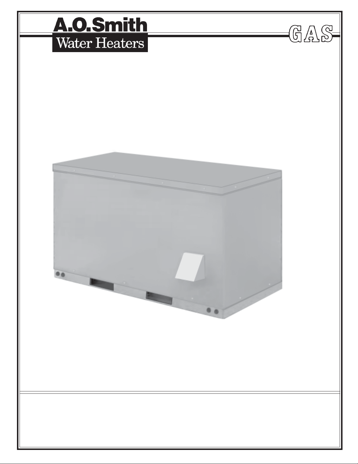
COMMERCIAL WATER HEATER PARTS LIST
MODEL RTF-120
SERIES 104
A.O. SMITH WATER PRODUCTS COMPANY
500 TENNESSEE WALTZ PARKWAY, ASHLAND CITY, TN 37015
PHONE: 1-800-433-2545 • FAX: 1-800-433-2515
Website: www.aosmithwaterheaters.com
PRINTED IN U.S.A. 0905 PART NO. 197241-000
1
SUPERSEDES PART NO. 196528-000
Page 2
Item Qty. Description Part Number
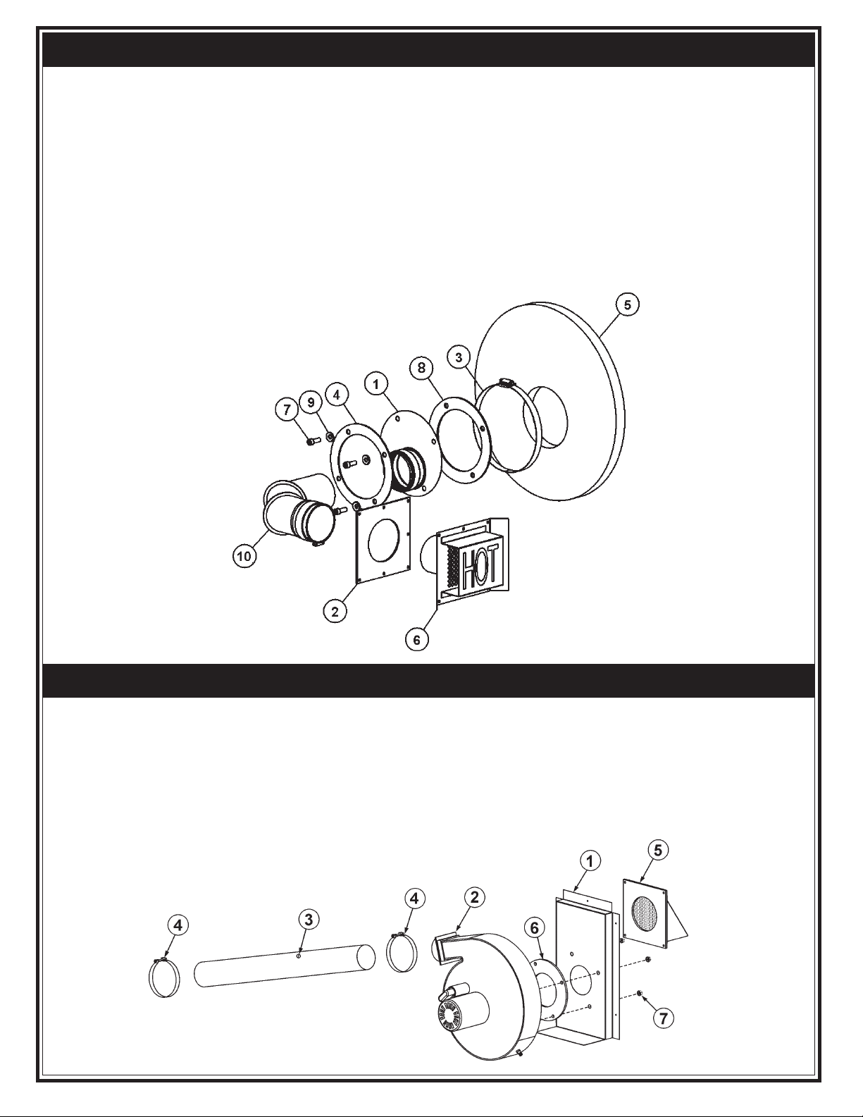
1....................... 1............................ Transition Pipe Assembly ............................... 196499-000
2....................... 2............................ Vent Terminal Gasket ...................................... 196496-000
3....................... 1............................ Clamp - Hose ................................................... 196813-000
4....................... 1............................ Reinforcement Ring ........................................ 196505-000
5....................... 1............................ Insulation - Flue Extension .............................. 196513-000
6....................... 1............................ Exhaust Vent Terminal Assembly ................... 196891-000
7....................... 4............................ Screw - Socket Head Cap ............................... 192515-002
8....................... 1............................ Gasket .............................................................. 192331-000
9....................... 4............................ Washer ............................................................. 196153-000
10...................... 1 ............................ Elbow - Vent, 90 Degree.................................. 196892-000
EXHAUST SYSTEM ASSEMBLY
Item Qty. Description Part Number
1........................ 1 ..............................Blower Plenum ............................................... 196490-000
2........................ 1 ..............................Blower Assembly ............................................ 196491-000
3........................ 1 ..............................Tube - Air ........................................................ 192469-024
4........................ 2 .............................. Clamp - 3 "....................................................... 192696-000
5........................ 1 ..............................Air Intake Assembly........................................ 196492-000
6........................ 1 ..............................Gasket - Intake Side ....................................... 193883-000
7........................ 4 ..............................Nut - Kep 1/4"-20 UNC ................................... 191763-000
AIR SYSTEM ASSEMBLY
2
Page 3
Item Qty. Description Part Number
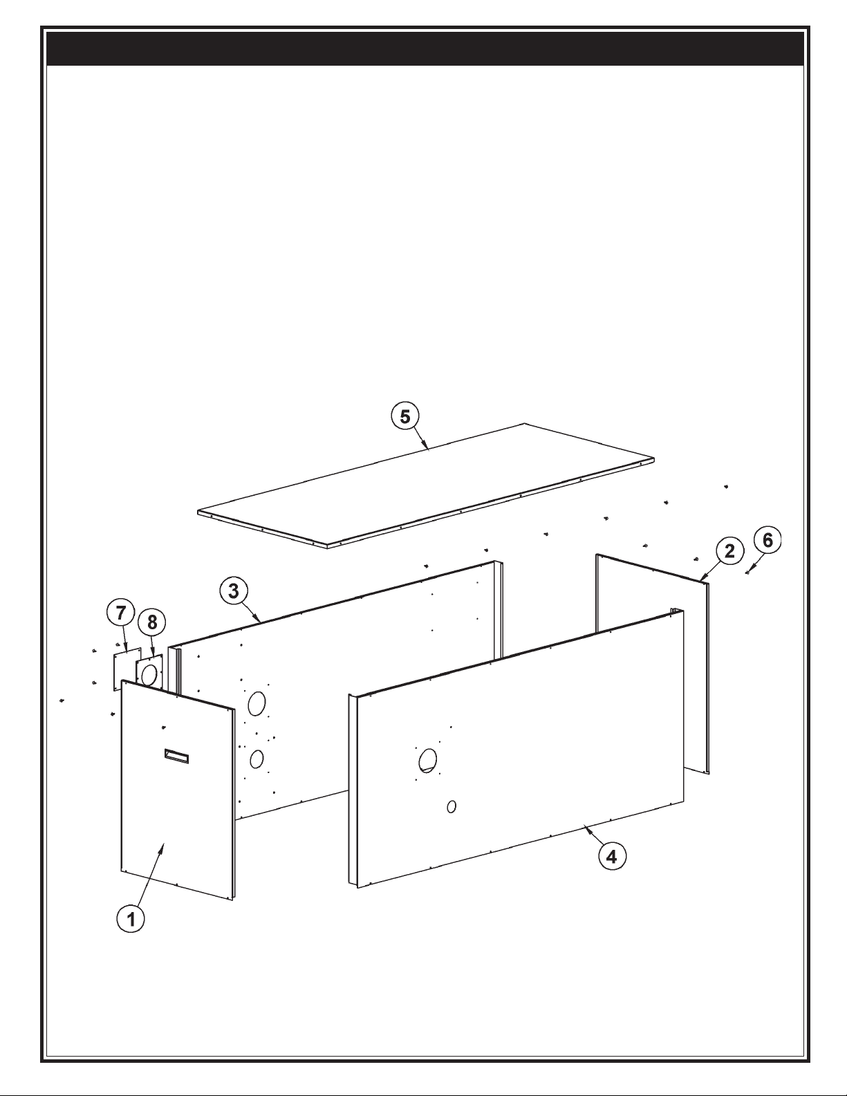
1....................... 1...............................Front Door Assembly ..................................... 196861-000
2....................... 1...............................Back Door Panel ............................................ 196862-000
3....................... 1...............................Side Panel - Left............................................. 196863-000
4....................... 1...............................Side Panel - Right .......................................... 196864-000
5....................... 1...............................Cover - Top, Equinox ...................................... 196815-000
6...................... 22..............................Screw - Self Sealing, #8-18 ........................... 210125-000
7....................... 1...............................Coverplate - Exhaust ...................................... 196914-000
8....................... 1...............................Vent Terminal Gasket .................................... 196496-000
CABINET ASSEMBLY
3
Page 4
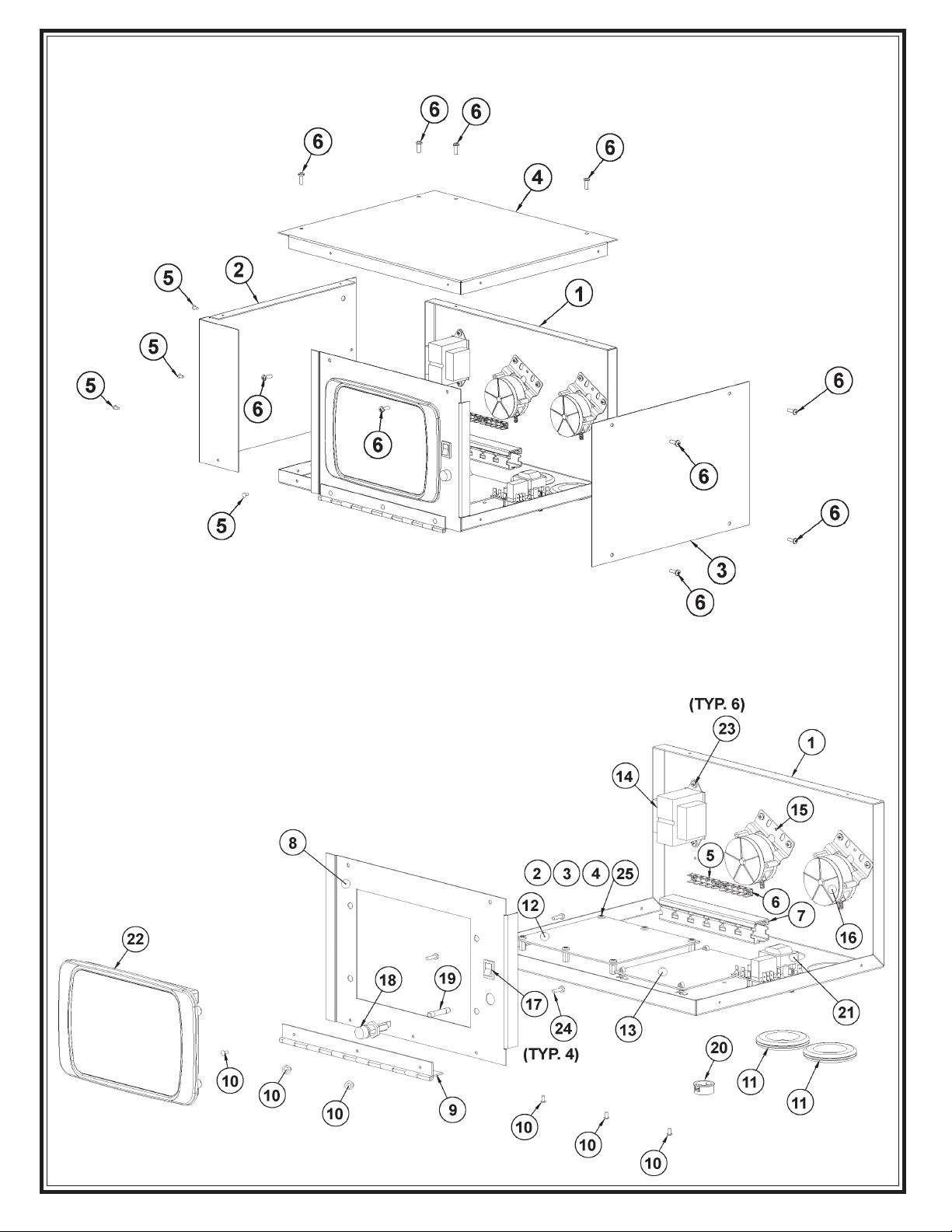
CONTROL ASSEMBLY
CONTROL ASSEMBLY - BOTTOM PANEL
4
Page 5

Item Qty. Description Part Number
CONTROL ASSEMBLY
1....................... 1....................... Bottom Panel Assembly - Controls Enclosure .... 196984-000
2....................... 1.......................Panels - Controls Enclosure, Left Side ................ 196979-000
3....................... 1.......................Panels - Controls Assembly, Right Side ............. 196982-000
4....................... 1.......................Panel - Controls Assembly, Top ........................... 196980-000
5....................... 4.......................Rivet ....................................................................... 068461-004
6...................... 10......................Screw-Self Threading ........................................... 181626-000
Item Qty. Description Part Number
CONTROL ASSEMBLY - BOTTOM PANEL
1....................... 1.......................Panels-Controls Enclosure, Bottom Back ........... 196981-000
2....................... 6....................... Standoff - Male/Female Threaded ........................ 196671-001
3....................... 6.......................Washer-Lock ......................................................... 003347-001
4....................... 6.......................Nut-Hexhead, #8-32 UNC ..................................... 041284-001
5....................... 2.......................Terminal-Quick-fit .................................................. 196683-000
6....................... 4.......................Screw-Thread Forming ......................................... 182487-000
7....................... 1.......................Slotted Wire Duct ................................................... 212448-006
8....................... 1.......................Panel - Controls Enclosure, Front ........................ 196983-000
9....................... 1.......................Hinge - Piano ......................................................... 210275-005
10...................... 6 .......................Rivet ....................................................................... 068461-004
11...................... 2 .......................Grommet ................................................................ 196635-000
12...................... 1 .......................I/O Board Equinox ................................................. 196589-000
13...................... 1 ....................... Ignition Control Board Equinox............................. 196586-000
14...................... 1 .......................Transformer - 120/24 Vac, 40 VA.......................... 196765-000
15...................... 1 .......................Pressure Switch - Air N.O. + 1.32" W.C. ............... 196572-000
16...................... 1 .......................Pressure Switch - Air N.C. + 1.32" W.C. ............... 196571-000
17...................... 1 .......................Switch - On/Off ....................................................... 193243-000
18...................... 1 .......................Fuse Holder ........................................................... 196749-000
19...................... 1 .......................Fuse - 8A, 250V, 1/4" - 1 1/4" ................................
20...................... 1 .......................Bushing - Snap ...................................................... 098863-000
21...................... 1 .......................Low Water Cutoff Board ........................................ 196590-000
22...................... 1 .......................Module - User Interface - Equinox ........................ 196594-000
23...................... 6 .......................Screw - Self Threading .......................................... 181626-000
24...................... 4 .......................Screw - Thread Forming ....................................... 182487-001
25...................... 6 .......................Machine Screw ...................................................... 191937-003
196835-000
5
Page 6

Item Qty. Description Part Number
1 1 Burner Assembly ....................................................................196162-001
2 1 Ignitor Assembly .....................................................................192638-000
3 3 Screw-Slotted Hex Sheet Metal - #6-3/8" ..............................194113-000
4 1 Air Restrictor ...........................................................................192450-006
5 1 Barb - Hose ............................................................................ 192800-001
6 1 Flame Rod Assembly ............................................................ 192478-000
7 2 Screw (Sheet Metal) ...............................................................039051-001
BURNER
ASSEMBLY
LABEL SET
Part Name Qty. Part Number
Envelope - Plastic ..................................1 ......... 041926-000
Gas Tag ..................................................1 ......... 183305-000
Instruction Manual .................................1 ......... 197240-000
Label - Air Intake ....................................1 ......... 196614-000
Label - ASHRAE Standard.....................1 ......... 160659-001
Label - Boiler Water Warning ................1 ......... 192919-000
Label - Caution .......................................1 ......... 196621-000
Label - Combination ..............................1 ......... 196618-000
Label - Dip Tube Orientation Outlet ......1 .........197239-000
Label - Dip Tube Orientation Inlet .........1 ......... 197239-001
Label - Equinox Nameplate ................... 1 .........196609-000
Label - Exhaust ......................................1 ......... 196613-000
Label - Flammable Vapors ....................1 ......... 183301-000
Label - FTC (Shipping) ..........................1 ......... 183731-000
Label - Gas Supply ................................ 1 ......... 196611-000
Label - “HOT” Label ............................... 2 .........196647-000
Label - Hot Return .................................2 ......... 196617-000
Label - Inlet ............................................. 2 .........094518-000
Label - L&O ............................................ 1 ......... 196620-000
Label - Outlet ..........................................2 ......... 094519-000
Label - Relief Valve ................................ 1 ......... 191068-000
Label - T&P.............................................2 ......... 098987-000
Label - UL Sanitation .............................1 ......... 194940-000
Label - 800 Help Line ............................1 ......... 190600-000
Label - Power In .....................................1 ......... 196610-000
Label - Wiring Diagram .........................1 ......... 196894-000
Replacement Parts List .........................1 ......... 197241-000
ADDITIONAL PARTS
Part Name Qty. Part Number
T & P Valve ..............................................1 .......... 099465-007
Pressure Switch Tubing ....................... 59" ........ 210209-059
Pipe Grommet .........................................1.......... 196520-000
Pipe Grommet w/Studs ..........................1.......... 196521-000
Pipe Grommet .........................................1.......... 196599-000
Wiring Harness .......................................1.......... 197002-000
Conduit Clamp for Remote Wiring .........1 .......... 196752-000
Upper Probe ............................................1.......... 196699-000
Lower Probe ............................................1.......... 196700-000
Control Box Support Bracket...................1.......... 196750-000
Junction Box ............................................1.......... 068595-000
Cover, Junction Box ................................1.......... 002233-000
Snap Bushing .........................................5.......... 098863-000
Cable Tie Mount ......................................6.......... 211238-000
Clip Retainer ..........................................10 ........ 092979-000
Screw-Special #8 Sems ........................10 ........ 097930-000
Gas Valve Bracket...................................1.......... 197000-000
6
Page 7

Item Qty. Description Part Number
1 ........................ 1 ........................ Tee - 1/8" NPT...................................................... 040119-000
2 ........................ 1 ........................ Union - Pipe, 3/4" ................................................. 095515-000
3 ........................ 1 ........................ Switch - Low Gas Pressure ................................ 191149-006
4 ........................ 1 ........................ Orifice Holder ....................................................... 192447-000
5 ........................ 1 ........................ Orifice................................................................... 192477-003
6 ........................ 1 ........................ Coupling - 3/4" NPT (Black Iron)......................... 196532-000
7 ........................ 1 ........................ Nipple - Pipe, 1/8"................................................ 192948-000
8 ........................ 1 ........................ Nipple - Pipe, 3/4" (2" Long) ................................ 194921-000
9 ........................ 1 ........................ Nipple - Pipe, 3/4" (1.48" Long) .......................... 194921-005
10 ....................... 1 ........................ Valve - Gas........................................................... 196632-000
11 ....................... 1 ........................ Elbow - 45 Degree 3/4" NPT, Street .................... 196531-000
12 ....................... 1 ........................ Nipple - Pipe, 1/2" (8" long)................................. 002251-014
GAS TRAIN
Item Qty. Description Part Number Item Qty. Description Part Number
FLUE BAFFLE ASSEMBLY: DIP TUBE:
1...........1 ............. Flue Baffle ................ 196515-000 1............ 1 ..................Dip Tube ................. 196517-000
FLUE BAFFLE
ASSEMBLY
DIP TUBE
7
Page 8

INLET MANIFOLD
MANIFOLD ASSEMBLY
OUTLET MANIFOLD
8
Page 9

Item Qty. Description Part Number
INLET MANIFOLD
1 .................... 1 ................ Valve, Drain ........................................................ 026273-000
2 .................... 1 ................ Tee - 3/4" x 3/4" x 3/4" ....................................... 196466-000
3 .................... 1 ................ Tee - 1 1/2" x 3/4" x 1 1/2" ................................. 196466-003
4 .................... 1 ................ Adapter - Fitting (Copper) ................................... 196475-000
5 .................... 1 ................ Elbow - 90 Degree, 3/4" (FTG x FTG)................. 196538-000
6 .................... 1 ................ Tube - Copper, 1-1/2" (3" long)............................ 196816-001
7 .................... 1 ................ Tube - Copper, 1-1/2" (6-11/16" long).................. 196816-012
8 .................... 1 ................ Tube - Copper, 3/4" (2-1/4" long)......................... 196813-003
9 .................... 1 ................ Tube - Copper, 3/4" (5-7/16" long)....................... 196818-013
10 ................... 1 ................ Adapter - Fitting, 3/4" ......................................... 196886-000
11 ................... 1 ................ Adapter - Fitting, 1-1/2" ...................................... 196886-001
12 ................... 1 ................ Cartridge Circulator............................................. 196875-000
13 ................... 1 ................ Union - Dielectric, 1-1/2"..................................... 196877-000
14 ................... 1 ................ Grommet ............................................................ 196887-000
15 ................... 1 ................ Grommet ............................................................ 196887-001
Item Qty. Description Part Number
OUTLET MANIFOLD
1 .................... 1 ................ Elbow - 90 Degree, 1-1/2"................................... 196465-003
2 .................... 1 ................ Tube - Copper, 1-1/2" (26-11/16" long) ................ 196816-010
3 .................... 1 ................ Tube - Copper, 1-1/2" (17-15/16" long) ................ 196816-011
4 .................... 1 ................ Adapter - Fitting, 1-1/2" ...................................... 196886-001
5 .................... 1 ................ Union - Dielectric, 1-1/2"..................................... 196877-000
6 .................... 1 ................ Grommet ............................................................ 196887-001
9
Page 10

Item Qty. Description Part Number
1....................... 1.......................... Base - Cabinet .................................................... 196884-000
2....................... 1.......................... Support - Cabinet Base, Side ............................ 196433-000
3....................... 1.......................... Support - Cabinet Base, Side ............................ 196464-000
4....................... 2.......................... Support - Cabinet Base, End ............................. 196434-000
5....................... 4.......................... Tank Support Assembly ..................................... 196435-000
6....................... 2.......................... Brace - Base Reinforcement .............................. 196438-000
7...................... 30......................... Nut - Speed, Spring ............................................ 196429-000
8...................... 66......................... Screw - Self Sealing, #8-18................................ 196640-000
CABINET BASE ASSEMBLY
Item Qty. Description Part Number
1 ..................... 1 ..................... Low Water Cutoff Probe ................................ 196591-000
LOW WATER CUTOFF PROBE
10
Page 11

NOTES
11
Page 12

A.O. SMITH WATER PRODUCTS COMPANY
500 TENNESSEE WALTZ PARKWAY, ASHLAND CITY, TN 37015
Phone: 1-800-433-2545 • Fax: 1-800-433-2515
Website: www.aosmithwaterheaters.com • E-mail: www.hotwater.com/parts
12
 Loading...