

Page 1

Innovation has a name.
LILY
Reverse Osmosis User Manual
Ters Osmoz Kullanma Kılavuzu
Page 2

Page 3

ENG 1
Dear customer,
Thank you for purchasing a "A.O. Smith" branded water purier!
You are now the owner of water treatment equipment produced by the world’s leading
manufacturer of water treatment systems. This equipment produces pure water that can
be consumed directly, providing you with a cleaner and healthier source of drinking water.
Please read this user manual carefully before you install and operate your
"A.O. Smith branded" water purier. To achieve maximum efciency this user manual
provides detailed instructions regarding the installation of your water purier as well as
information related to the proper operation and maintenance of your water purier.
The installation should only be handled by professionals authorized by A.O. Smith
Su Teknolojileri A.Ş.
Spare parts used for maintenance and replacement lter should be approved
by A.O. Smith Su Teknolojileri A.Ş. before they are installed.
Any degradation of performance caused by the use of spare parts or lters that have not
been approved by A.O. Smith Su Teknolojileri A.Ş. will not be covered by our warranty.
If you experience any difculties during installation or operation, please contact your local
distributor to have them carry out repairs or maintenance on your equipment.
Page 4

ENG 2
CONTENTS
İÇİNDEKİLER
Page 5

ENG
SAFETY CONSIDERATIONS 4
PRODUCT DESCRIPTION 7
Brief Introduction 7
Description of Components 7
Electrical Diagram 8
Water Route Map 8
Technical Specications 9
Functions of Main Components 9
Functions of Accessories 10
Water Puriter Features 10
TRANSPORTATION 10
INSTALLATION METHODS 11
Pre-Installation Preparations 11
Instructions for Proper Installation 11
ADJUSTMENT METHODS 14
LED DISPLAY FUNCTIONS 15
SIDE STREAM R.O. MEMBRANE 17
OPERATION WARNINGS 18
MAINTENANCE AND REPAIR 19
Flushing the RO Membrane 19
Filter Replacement Interals 19
PACKING LIST 21
AFTER-SALES SERVICE 21
TROUBLESHOOTING GUIDE 22
TR
GÜVENLİK UYARILARI 26
ÜRÜN TANITIMI 29
Kısa Tanıtım 29
Su Arıtma Cihazının Ayrıntılı Proli 29
Elektrik Şeması 30
Su Akış Şeması 30
Teknik Bilgiler 31
Ana Bileşenlerin İşlevleri 31
Aksesuarların İşlevleri 32
Su Arıtma Cihazının Özellikleri 32
NAKLİYE 32
KURULUM TALİMATLARI 33
Kurulum İçin Ön Hazırlık 33
Doğru Kurulum için Uyulması Gereken Talimatlar 33
AYARLAMA YÖNTEMLERİ 36
LED EKRANIN İŞLEVLERİ 37
SIDE STREAM R.O. MEMBRAN 39
KULLANIM UYARILARI 40
BAKIM VE ONARIM 41
RO Membranın Yıkanması 41
Filtre Değişim Aralıkları 41
Filtre Değişim Yöntemleri 42
Genel Bilgiler 42
ÜRÜN KONTROL LİSTESİ 43
SATIŞ SONRASI SERVİS 43
ARIZA GİDERME KILAVUZU 44
YETKİLİ SERVİSLER 46
MONTAJ KONTROL KARTI 48
BAKIM KARTI 49
GARANTİ BELGESİ 50
Page 6
ENG 4
Safety Considerations
(Be sure to read and remember these safety considerations)
Make note of the following safety precautions In order to avoid property damage and harm to you and others.
•Ignoring the following safety precautions could result in risky situations for you, your water purier and your environment.
Warnings
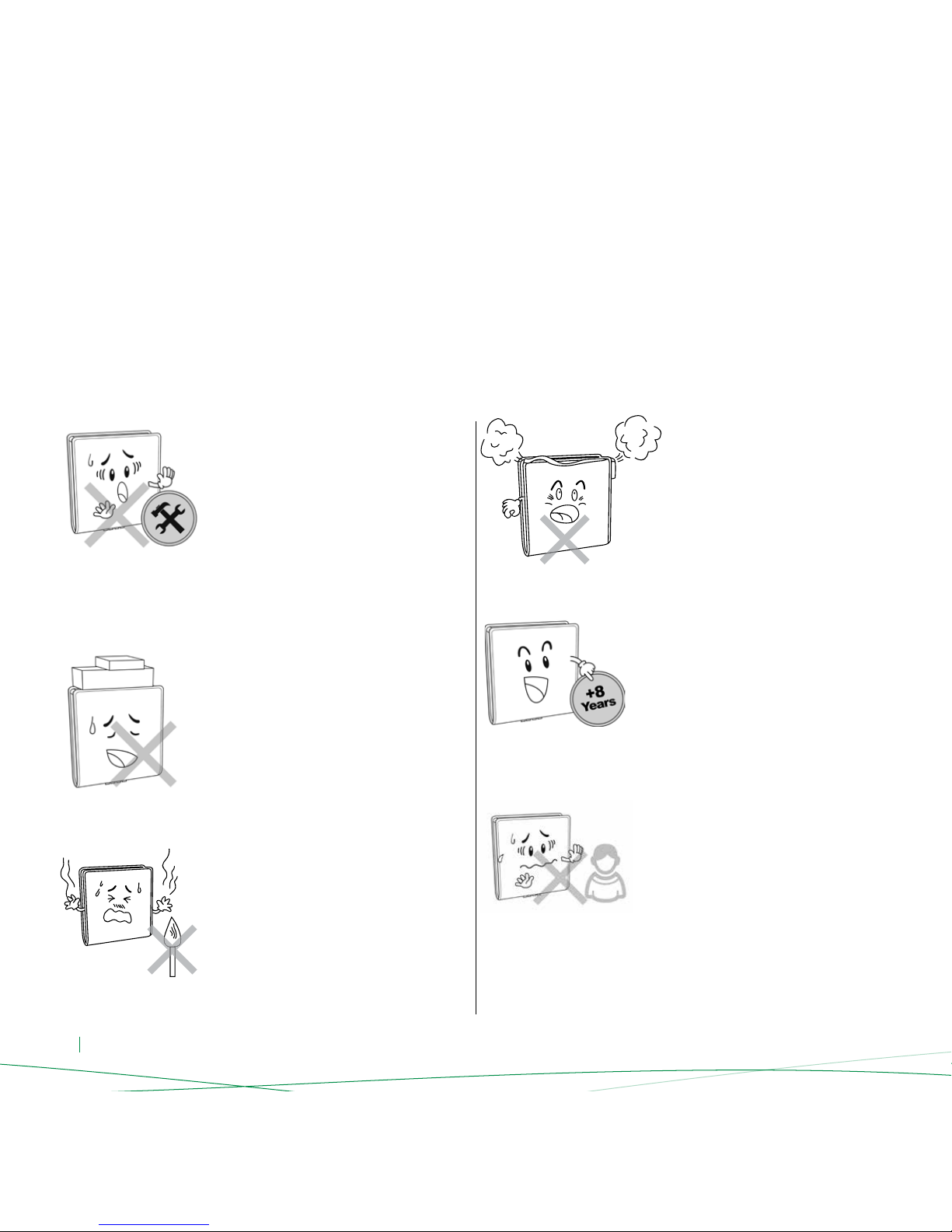
If you ignore contents in this section, it may cause permanent damage to the water purier or cause serious property damage.
Do not disassemble or modify this water
purier on your own!
Unauthorized disassembly or modication
of the machine could lead to machine
malfunctions or leakage accidents. Please
check with the store where you purchased
this product for product consultation in order
to arrange for repairs.
Do not put the water purier close
to a source of ames!
Do not put the water purier near a source
of ames or a place where the temperature
is too high as this may cause deformation or
melting of the machine, causing damage or
leakage, which could lead to serious bodily
and property damage.
Do not put heavy objects on the water
purier!
Placing heavy objects on the water purier
may cause damage to the water purier’s
external cover or internal components, which
in turn could lead to leakage, equipment
malfunctions or even serious property
damage.
Do not place any objects on top of your
water purier!
Obstructing the heat dissipation may lead to
machine damage or res.
This appliance can be used by 8 years and
older children and persons with reduced
physical and sensory capabilities only
when they have been given supervision or
instruction concerning use of the appliance by
a person responsible for their safety and they
have fully comprehend the possible risks of
the appliance.
As this appliance functions with electricty
and water, using the device by mentally
handicapped people is not advised.
Children should not be allowed to play with
the unit.
Cleaning and maintenance of the unit should
not be made by children without supervision.
Page 7
ENG 5
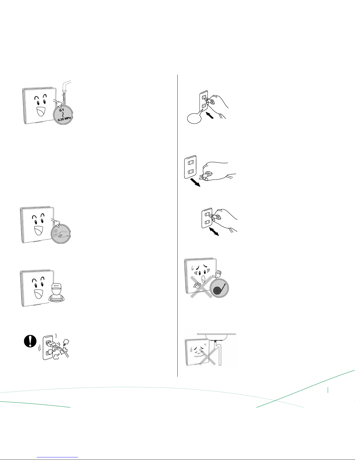
Do not use this water purier under high
water pressure conditions!
Operating under high pressure conditions
may cause the water purier pipes to rupture,
resulting in leakage, the machine working
improperly, or even serious property damage.
Recommended inlet pressure is
0.1-0.35 MPa (1 Bar to 3,5 Bars)
In places where inlet water pressure is
more than 0.35 MPa (3,5 Bars), it is
recommended to use a pressure reducer
before the unit.
Do not touch the power plug with wet hands!
It may lead to electric shock.
Do not damage the power cord
or the outlet!
Doing so may lead to electric shock, short
circuiting or re.
The equipment must be disconnected from
the power supply during installation
and repairs!
Otherwise it may lead to electric shock.
Do not use a power source exceeding
the equipment’s specied value. Use only
230V AC power!
The electrical current supplied to your
equipment by the outlet must not be greater
than the specied value; otherwise it may
lead to the overheating of your equipment
or re.
230 V
Unit should be installed and connected to
the water mains by new hose-set that was
included in the product package. Old
hose-sets should not be reused with the unit.
Otherwise water leakages may occur or
the unit’s performance may be affected
negatively.
Use only power supply unit (the supply cord
and the plug) that was provided with the unit!
Using the non-original power supply unit may
affect the performance of the unit negatively
and using unqualied parts may damage to
the unit.
If the supply cord is damaged, supply an
original cord from your A.O.Smith Sales Agent
or A.O.Smith Authorized Service!
Using the non-original supply cord unit may
affect the performance of the unit negatively
and using unqualied parts may damage to
the unit.
Do not use the water purier when the sewer
is blocked up!
If the purier is used while the sewer is
blocked, it may cause waste water to back
up into the purier and pollute the water
and parts inside.
Page 8
ENG 6
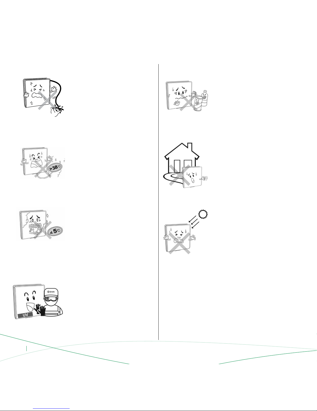
Do not place the water purier under direct
sunlight!
Placing the water purier under direct
sunlight for a certain period of time may
create a breeding ground for microorganisms;
decreasing the output water quality
and potentially causing the internal
components of the water purier
to become contaminated.
The waste water discharge pipe and
waste water rationing device cannot be
blocked!
When the waste water discharge pipes and
waste water rationing devices are obstructed
or clogged, it may lead to high levels of TDS
efuent, the RO membrane may get blocked
or the water purier may not work.
Do not use in conditions under 5°C!
If the ambient temperature falls below 5°C,
please be sure to take measures to prevent
freezing, such as turning on a heater or air
conditioner to prevent leakage or cracked
pipes caused by water freezing inside
the equipment.
Water purier inlet water temperature
should not exceed 38°C!
If the inlet water temperature is over 38°C,
it will damage the reverse osmosis membrane
leading to membrane failure.
Do not use this water purier outdoors!
If this water purier is used outdoors, it can
lead to accelerated aging of the
water purier pipes and parts, which can
cause leaking or machine failure.
Do not let the machine come in contact with
corrosive materials!
These materials could corrode the outer cover
and adversely affect various parts of the
equipment. Toxic and hazardous compounds
could penetrate the water purier pipes,
causing contamination of the water or
leakage, which in turn may cause personal
damage or property damage.
Do not use force on the glass panel and place
the water purier atly!
The reinforced glass panel needs to be put
lightly and atly. Otherwise it may lead to the
glass panel damage.
Do not remove the UV Protector
unauthorized!
• Wear protective goggles and gloves
while maintaining UV disinfection unit.
• Do not look directly to UV lamps while
they are on.
• During maintenance and repair, be sure
that UV unit is not active.
Otherwise UV light might lead damage to
the eyes and skin.
Page 9
ENG 7
Brief Introduction
This equipment utilizes the current, most advanced international
RO technology. RO technology relies on the articial reversing
of the naturally occurring osmosis phenomena. The RO membranes have
pores with a diameter of 0.0001 micron (0.1 nm), so they can effectively
remove bacteria, viruses, heavy metals, pesticide residue, and other harmful
substances from the water. Produced water is fresh, pure and suitable for
direct use.
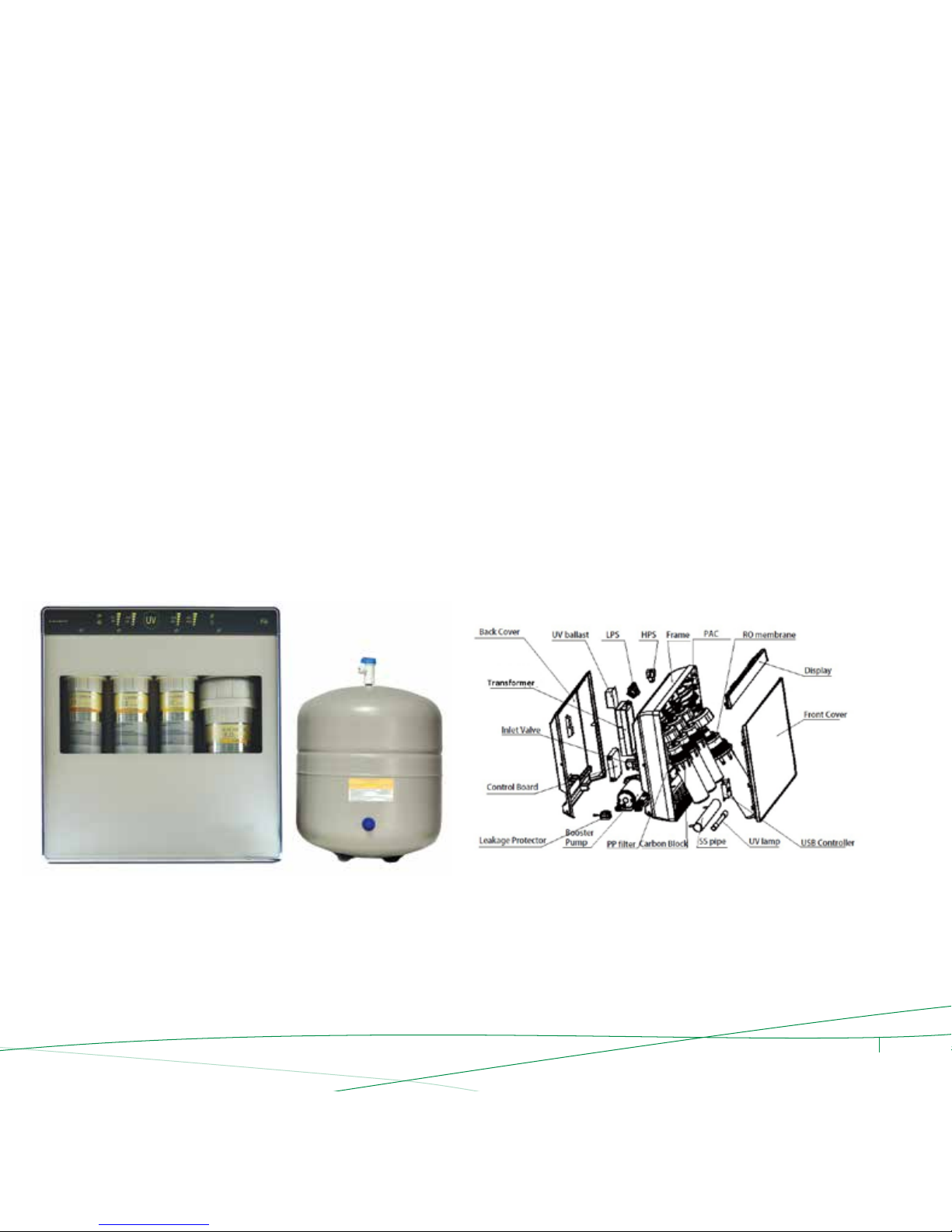
Description of Components
Product Description
Diagram 1
Lily
Page 10
ENG 8
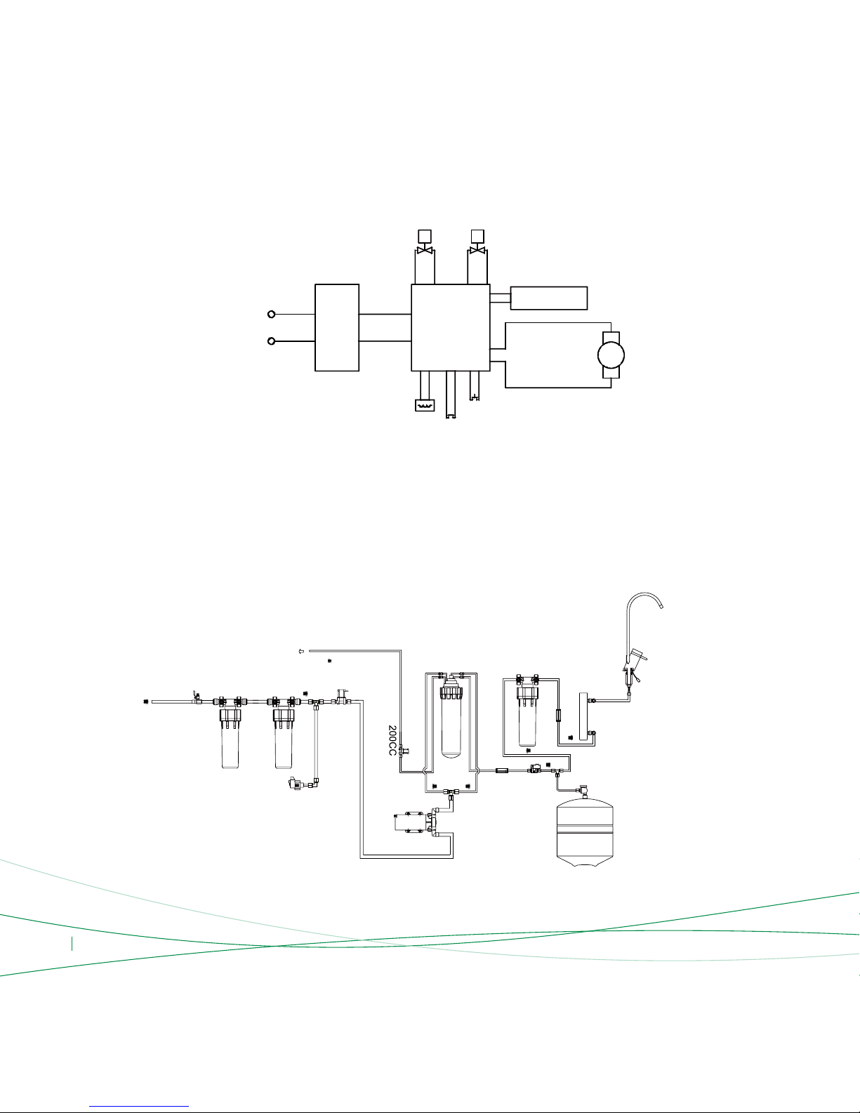
Electrical Diagram
Diagram 2
Diagram 3
Water Route Map
UV ballast LPS HPS Frame
PAC
RO membrane
Display
Front Cover
Switch Mode
Power Supply
Inlet Valve
Booster
Pump
PP filter
SS pipe
UV lamp
USB Controller
Reed Switch
Low Pressure Switch
High Pressure Switch
230V AC
24V DC
Inlet Water Valve
Flushing Valve
UV Lamp
Booster Pump
Power
Control Board
Carbon Block
3 way joint
Municipal
Water
Low Pressure Switch
Inlet Water Valve
Booster
Pump
High
Pressure
Switch
Tank
UV Lamp
Electronic
Faucet
Waste Water
Flushing Vavle
PP
RO
PAC
Check Valve
Tank Valve
Carbon Block
Check
Valve
Page 11

ENG 9
Functions of the Main Components
The standard conguration of the water purier that utilizes the current,
most advanced international RO technology is as follows:
• The rst stage is a 5-micron PP (Sediment) Filter:
The pores on the aperture within the PP lter is 5 microns wide so it
can effectively lter rust, sand, other larger particles and solid impurities
suspended in the water.
• The second stage is a Carbon Block Filter:
The lter effectively absorbs chlorine, mould, disinfection by-products,
odors, discolorations and other materials suspended in the water.
• The third stage is the RO membrane:
The RO membrane with a pore size of 0.0001 micron (0.1 nm), it can
effectively remove bacteria, viruses, heavy metals, pesticide residue, and
other harmful substances. Produced water is fresh, pure and suitable
for direct use.
• The fourth-stage is a Post Active Carbon (PAC) Filter:
This lter regulates the taste of water, keeps the water fresh.
• The fth-stage is a UV Disinfection:
This unit effectively restrains the water pipe and tank etc to breed the
bacteria after long time without use.
Note: the parameters above may change due to product improvements, but the product name plate shall remain the same. TDS refers to inuent total dissolved solids.
Note:
0.1 MPa = 1.02 Kg/cm
2
= 14.5Psi
1 Psi = 0.07 Kg/cm
2
1 Gallon = 3.785 Liters
75 GPD = 75 Gallons/Day = 284 Liters/Day = 197 Milliliters/Minute
Technical Specications
Model No.
Frequency
Voltage
Suitable Water Pressure
Inlet Temperature
Maximum Daily Water TDS Value
Flushing Method
Electric Shock Protection Type
Product Dimensions
Tank Dimensions
Weight
Suitable Water Quality
Power Rating
Daily Water Production Volume
Tank Volume
230V AC
50 Hz
38 W
0.1-0.35 MPa (1 Bar to 3,5 Bars)
5 ~38˚C
≤1000 PPM
Auto Flushing
75 Gallons, approximately 284 Liters
3.2 Gallons, approximately 12.1 Liters
Class II
Municipal tap water meeting the TS-266 standarts
LILY
460x488x161 mm
335x280 mm
14 kg
Page 12

ENG 10
Functions of Accessories
• Storage Tank: Used to store water ltered by the water purier.
• High Pressure Pump: Boosts pressure to create a stable environment
for the RO membrane.
• Flushing (Solenoid) Valve: Control the waste water ow and
automatically ush the RO membrane.
• Low Pressure Switch: Prevents pump idling. When the inlet water
pressure is less than 1 Bars or when the inlet water stops,
the low-voltage switch automatically shuts off the power source
so the machine comes to a halt.
• High Pressure Switch: Prevents pump from overdrive. When the pressure
tank is full or has reached the set pressure level, power supply is
automatically cut off to stop the operation of the machine.
• Inlet Water (Solenoid) Valve: Connects or cuts off incoming water.
• Check Valve: Also known as a one-way valve, controls the direction
of water ow.
• Transformer: Converts 230V AC to 24V DC (the machine's safe
operating voltage).
• Power Control Board: Control the whole process of water production.
• Leakage Alarm: Detect malfunction of water leakage timely to protect
user's safety and avoid the loss of user's property.
• E-Faucet: Controls the water output status of drinking water. Electronic
faucet indicates the lter life while it is on by changing the logo color.
• UV Disinfection Unit: Sterilizes the outlet of pure water.
Water Purier Features
• Side Stream Membrane: The Side Stream R.O. membrane increases
the recovery rate to around 50%, compared to 25% for the regular
residential R.O. membrane, and waste water volume is reduced by 56%.
• Automatic Control System: The system controls the whole water
production process, such as stopping automatically when there is no
inlet water or when the tank is full;
• Auto Flush Function: The system can automatically control the water
auto ush process for the RO membrane to ensure more reliable
and safe operation.
• Remind on Filter Replacement: While the lters are close to the service
life, system can remind the customers with sound and red colors to
replace the lters.
• Leakage Protection: While inspect there has water leakage, it will
automatically stop working, and power off the booster pump, inlet
valve to avoid risk on water leakage. And “Leakage” light ashing on
the display with buzzer warning. Only can be recovered after defect
solved and re-power on.
• UV Lamp Protection: Use the powerful radiation of short-wave
ultraviolet ray to effect on microorganism in water, so as to achieve the
bacteriostatic action of water
• Stock up on top of each other more than 6 pieces.
• Before lifting the packages be sure that xing tapes below the package
are intact.
• Lift the packages holding from bottom.
• Persons, who are vulnarable to heavy lifting shoud not carry the packages
to prevent any health issues.
Transportation
Please take into consideration the following points while transporting the device.
Page 13
ENG 11
Pre-Installation Preparations
• Choose the location where the water purier will be installed
• Conrm the availability of the various tools required
for installation
• Conrm that you have all the connectors required for installation
• Make sure to turn off the water supply and electricity before
commencing installation
Warning: In places where inlet water pressure is more than 0.35 MPa(3,5
Bars), it is recommended to use a pressure reducer before the unit.
Installation Methods
Our company recommends that your water purier is installed by trained professionals as the installation process is somewhat complex and requires the
use of various tools. However, if you decide to install the purier yourself, please refer to the following steps and diagrams:
Adjustable Spanner
Drill
6.2 mm Drilling Bit
Hole Saw φ16-35 mm
T10 Cross and Flathead Screwdrivers
Scissors
14 - 16 mm Wrench
19 - 21 mm Wrench
Needle Nose Pliers
1
1
1 (Waste water hole)
1
1 of each
1 pair
1
1
1
Instructions for Proper Installation
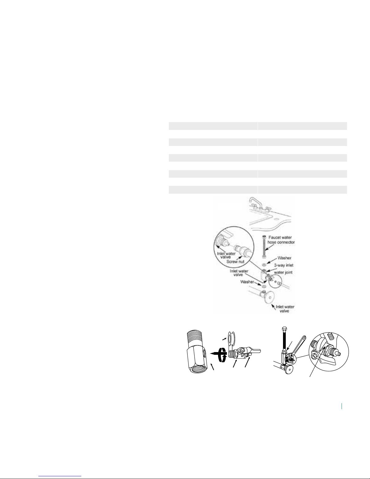
• Installation of the inlet water metal hose and 3-way inlet water joint:
(If the metal hose diameter is equal or less than 9 mm, the 3 - way inlet
water joint should be connected to the unit) First, close the inlet water
valve. Screw off the metal hose. Remove the 3-way inlet water joint
from the water purier accessories box, screw one end of the inlet water
3-way joint onto the inlet water valve outlet. One end of the unscrewed
metal hose should be screwed into the 3-way inlet water joint using the
screw nut (See Diagram 4)
• Installation of the 3-way inlet water joint and inlet water ball valve:
Take out the inlet water ball valve from the water purier accessories
box, wrap one end of the external threads on the ball valve with appro
priate teon tape (See Diagram 5). If you have silica gel, spread a little
over the thread and then screw the ball valve into the corresponding hole
of the 3-way inlet water joint (See Diagram 5). Take out the Ø 9mm
water pipe from the accessories box. Using a pair of scissors, cut
a suitable length of pipe and connect one end of the pipe to
the inlet water ball valve (See Diagram 6). Finally screw the nut in place.
Diagram 4
Diagram 5
3-Way inlet
water joint
Inlet water
ball valve
Teon tape
Water pipe
connection
Diagram 6
9mm Ball valve
Inlet water
3-way
joint
Diagram 6
Page 14
ENG 12
• Installation of inlet tube:
Take out the 1/4” tube from the accessory box, and cut to suitable
length with scissors, connect one end of the inlet tube to the inlet end of
the 3-way joint (See Diagram 4), then screw the nut tightly. The other
end of inlet tube connect to the “Source” of the unit connector.
Note to x the tube and quick connector to avoid water leakage issues.
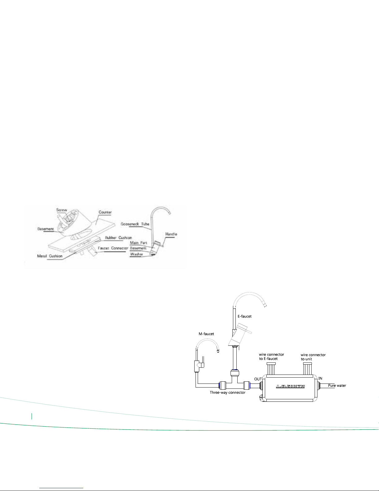
• Installation of the electronic faucet:
Drill a φ20-35 mm hole in an appropriate position on the counter where
the faucet is to be installed. Then take out the faucet from the water
purier accessory bag. Begin the installation of the faucet. In the
counter where the faucet is to be installed, drill a 20-35mm hole in an
appropriate position, then take out the faucet from the water purier
accessory bag, start the faucet installation (See Diagram 7):
A) Basement Installation: install the rubber cushion into the metal cushion,
take out 2 pieces M4mm screw, and x the screw on the metal cushion
through the basement hole, then pull the connectors of faucet through
the basement Pull the faucet cable through the plastic basement, rubber
cushion and the metal cushion in series, and combine the rubber cushion
and metal cushion together, then take out the M4mm screws and x one
screw to metal cushion started from plastic basement. Then put the plastic
basement through the sink hole and insert the cushions, then install
another screw and x tight 2 screws.
NOTE: don’t x the screw to tight once, it should be xed in steps, and
don’t use strong force.
B) Main Part Installation:
Cut a suitable length 1/4” tube and insert one end into the bottom quick
snap of main part, and connect another end to the “Source” connector
of the unit, then press down the main part on the basement.
C) Gooseneck Installation
Make sure all 3 O rings are in the O ring slot of gooseneck tube, then dip
some water on the end with O rings, then insert into the output nozzle of
main part.
• Installation of the Second Faucet Outlet Converter
Lily water treatment system can be connected to outlet connection with
the converter that comes as standard feature inside the package. With
this converter, it possible to connect the system to your refrigerator or to a
second faucet.
Water System Connection:
Connect the pure water pipe to the converter IN end then connect the
OUT end to the one end of three-way connector, after that connect other
two ends of the three-way connector to the E-faucet and M-faucet.
Electrical System Connection:
Connect the one wire connector on the converter to the E-faucet and the
other one connect to the wire from the units. These wire are apple to
apple connection.
Diagram 7
Page 15
ENG 13
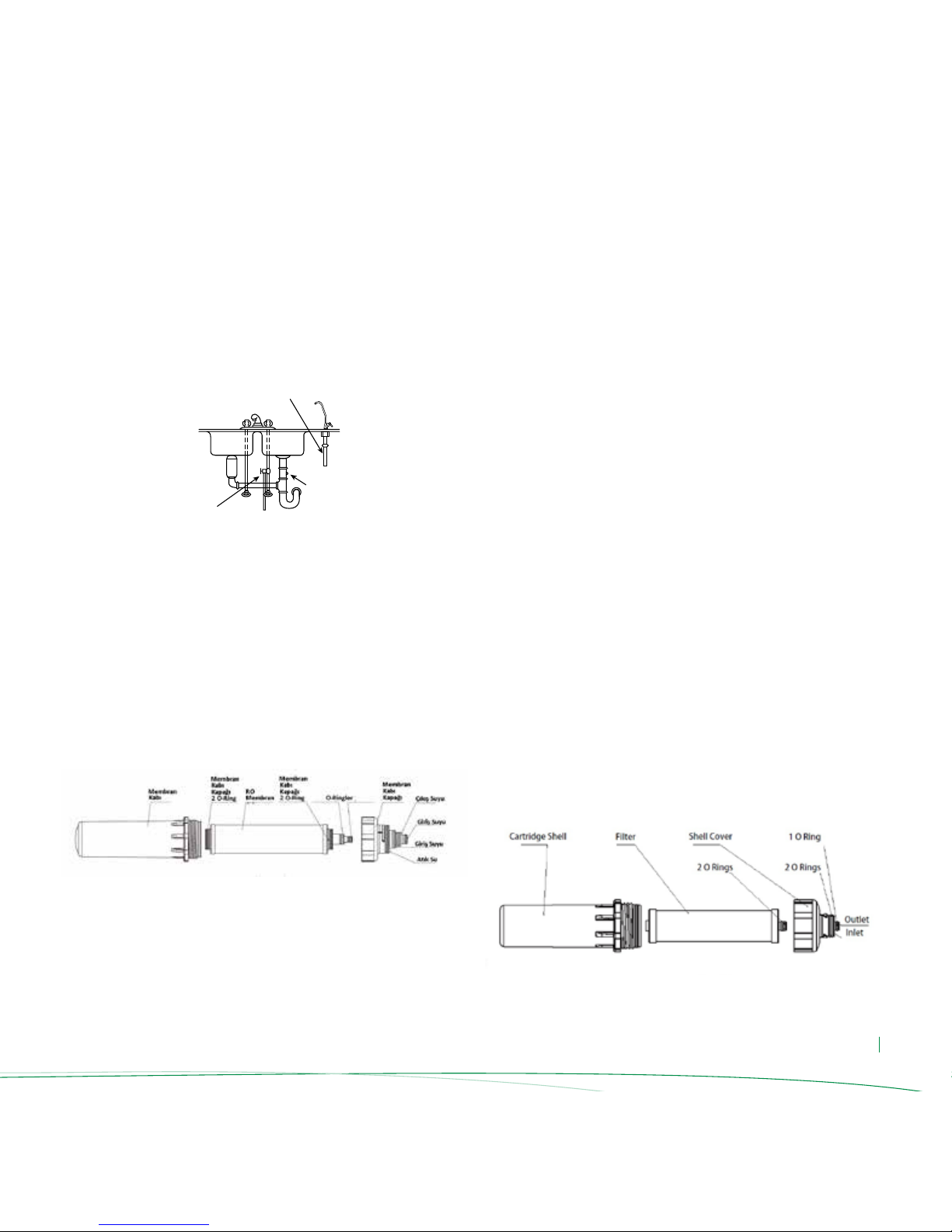
• Installation of the waste water pipe:
Drill a small hole into the sink drain pipe using a φ 6mm drill. Take
a suitable length of the 6mm water pipe and lay one end just inside
the drilled hole (See Diagram 8), put some silica gel where the 6mm
pipe and the drain pipe connect to prevent leakage. Use a cable tie to x
the waste water pipe to the drain pipe (for large ow water puriers;
you will need to insert a waste water clip into the drilled drain pipe hole).
The other end connect to the ''Waste'' at the back of the machine.
• Installation of the Side-Stream RO Membrane:
Open the front cover, pull up and out the RO lter assembly about 15°,
then rotate anticlockwise to take out, then use wrench to remove
the shell cover; then take out the RO membrane from the vacuum
bag, keep all O ring installed (See Diagram 9), put the at end of RO
membrane intothe shell and xed, then rotate the shell cover and tighten
with wrench,after that install the RO lter assembly into the front cover
in clockwise, and push inside until in originally vertical.
• Membrane Installation Warnings:
• The package of the reverse osmosis membrane contains a small amount
of protective solution in order to prevent microbiological contamination
of membrane components during storage and transportation.
• You should pay attention to the direction of the RO membrane during
installation.
• When installing the RO membrane, rst make sure that one end of the
membrane has 2 large O-rings and the other end has two large and
four small O-rings.
• When installing, be sure to put the end with 2 O-rings into the
membrane shell RO outlet water connection. Be sure when installing
to only use a little force to put the RO membrane into the membrane
shell. If you encounter too much resistance, please do not force the
reverse osmosis membrane into the membrane shell, doing so may cause
permanent damage to the membrane shell or membrane components.
A.O. Smith does not assume responsibility for returned components due
to damage during installation.
• Check the grey rubber bracket whether under the RO membrane
assembly, can not missing.
• Do not cut or try to disassemble the replaced membrane. RO membrane
can lter microorganisms and cutting or harming RO membrane may risk
on you and your environments health
• Installation of the Pre-Filters:
Open the front cover, pull up and out the RO lter cartridge assembly
about 15°, then rotate anticlockwise to take out, then use wrench to
remove the shell cover;Then take out the lters from package, keep 2 o
rings installed (See Diagram 10), put the end without O ring of lters into
the cartridge shell and xed, then rotate the shell cover and tighten with
wrench,after that install the RO lter cartridge assembly into the front
cover in clockwise, and push inside until in originally vertical.
The 1st stage lter is PP lter, 2nd stage is carbon block lter, and 4th stage
is PAC lter.
Diagram 8
Pure water pipe
Hot
Cold
Inlet water ball valve
Waste water hole
Diagram 10
Diagram 9
Page 16
ENG 14
• Open the tap water inlet valve and the water purier inlet water ball
valve (See Diagram 13) and plug the unit in the power outlet. Close
the storage tank ball valve, then automatically start a 120 second
ushing process, water will start to drain through the discharge outlet.
• Wait for the water purier to operate stably (for about 5-10 minutes).
Check each connection to make sure they are secure. Check to see if
there is any leakage from the membrane shell, lters, etc.
• Close the pure water osmosis faucet and storage tank ball valve. Wait
approximately 30 seconds. Check to see whether or not the water
purier waste water and high pressure pump have stopped working.
• Open the osmosis faucet. Check to see if the water is owing through
the faucet. If not, check to see whether the tap water pressure is too low
or whether or not the high pressure switch can be reset automatically.
• Wait until the machine is operating properly, then close the inlet water
ball valve. After a short period of time, check to see if the machine stops
working, if it does not stop working, check to see whether or not
the low-pressure switch can be reset.
• Perform a second check to make sure everything is ok. Now your water
purier is ready for use.
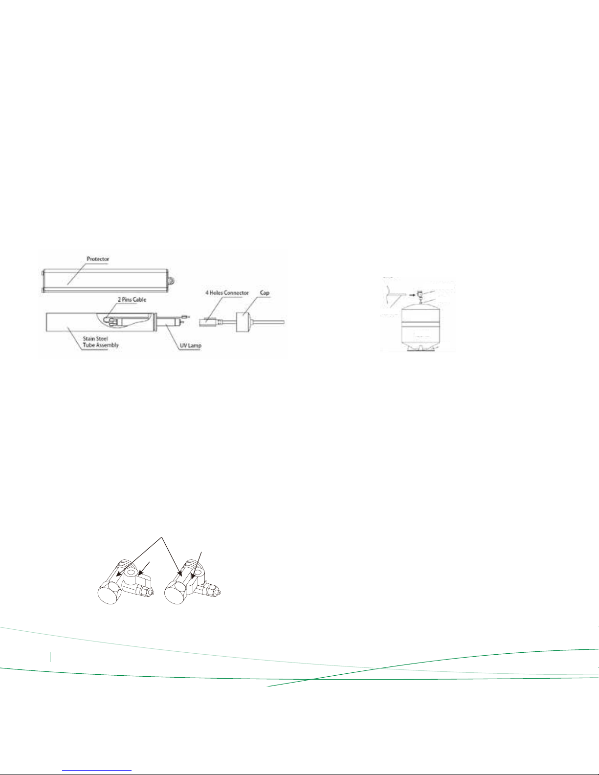
• Installation of UV Lamp:
First be sure that the water inlet and electricity connections are cut off from
the unit. Open the front cover, remove the UV lamp protector, and take
out the UV lamp and 2 pin cables from package, put one end 2 pins of UV
lamp into the hole end of cable connector, then put another end 2 pins of
UV lamp and 2 pins plug of cable together into the 4 holes end connector
and tight. Then install the cables and UV lamp into the stain steel tube
assembly, and make sure the 4 holes connector also inside, then cover the
end with cap and x the cover (See Diagram 11).
• RO Unit Placement:
Lily RO unit is not wall hung type, and need put on the ground or solid at
surface directly. If choice to hung on the wall, need to purchase additional
expand bolts and screws for xation.
• Installation of the Storage Tank:
Wrap 4-5 rounds thread seal tape on the tank nozzle, then x the tank
valve into the tank nozzle, then cut out a suitable length 1/4” tube, put one
end of tube on the tank valve, and another end connected to the “Tank”
joint of the unit (See Diagram 12). After that, nd a suitable place to locate
the tank in the cabinet.
Diagram 11
Diagram 12
Diagram 13
Adjustment Methods
Make sure that the water route connections are correct, proper power supply is used and water supply is suitable.
Then, follow these steps to adjust the purier:
3-Way Joint
Close
Open
Tank Valve
Nozzle
1/4”
Tube
Tank
Base
Page 17
ENG 15
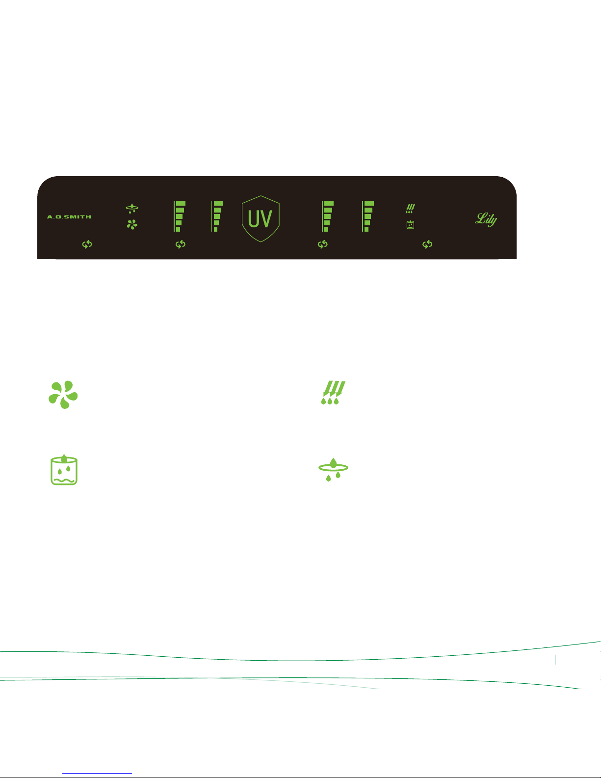
LED Display Functions
1st
PP
2nd
CB
3rd
RO
4th
PAC
Work: When the machine is producing water, this icon will lit up.
Source: When the machine has no inlet water or the inlet water is not
enough, this icon will lit up and the alarm will buzz.
Flush: When the unit is flushing the membrane, this icon will lit up.
Leakage: When there is a water leakage, this icon will lit up and the alarm
will buzz.
UV: This icon indicates the remaining life of UV Lamp.
Replace: These icons will be lit when one of the filters need to be replaced.
1st PP: This icon indicates the remaining life of 1st stage Sediment Filter.
2nd CB: This icon indicates the remaining life of 2nd stage Carbon Block
Filter.
3rd RO: This icon indicates the remaining life of 3rd stage RO Membrane
Filter.
4th PAC: This icon indicates the remaining life of 4th stage Post Active
Carbon Filter.
Work
• This icon will lit up only when the unit is producing
water.
• When the unit is in standby mode, this icon will be off.
Flush
• This icon will lit up only when the unit is flushing the RO
membrane.
• When the unit is in standby mode, this icon will be off.
Source
• When the machine has no inlet water or the inlet water
is not enough, this icon will lit up in red color and the
alarm will buzz..
• Alarm will buzz 7 times, after the buzzing, alarm will be
off and this icon will blink on the display.
• Alarm will buzz 7 times only once but everytime when
the water cut, the alarm will buzz again.
• This function and alarm will be activated when water is
cut no matter the unit is treating water or in standby.
Leakage Sensor and Alarm
• When there is a water leakage inside the unit, solenoid
valve will cut the water and leakage alarm will be
activated. .
• When Leakage Alarm is activated this icon will be
blinking in red color and alarm will buzz in each 2
seconds continuously.
• Alarm can be off only when the power source is the
unit is cut and reconnected to power again.
• Leakage alarm will be activated and the inlet water
will be automatically cut off no matter the unit is
treating water or in standby.
Page 18

ENG 16
1/2/3/4 Filter Life Status and Replace:
•These numbers indicates the remaining life of four
different filters. When the remaining of filter life changes,
the color of these icons will change.
• Number 1 indicates 5 µm Sediment Filter, Number
2 indicates Carbon Block Filter, Number 3 indicates RO
Membrane Filter and Number 4 indicates Post Active
Carbon Filter.
• When the related icon is Green, the filter can be used
normally.
• When the related icon turns to Orange and alarm is
buzzing 4 times, it means the filter should be replaced
soon.
After the icon turns orange on the display, the alarm will
buzz 4 times evertime the unit is treating water, this icon
willl remain until the related filter is replaced.
• When the icon turns Red and Replace icon is blinking
in Red color with alarm is buzzing 8 times, it means
the related filter can not be used and needs replacing
immediately. The unit should be stopped functioning and
call the After Sales Service for filter replacement
After the icon starts blinking on the display, the alarm will
buzz 8 times evertime the unit is treating water. This icon
willl remain blinking until the filter is replaced.
• This function and alarm will be activated no matter the
unit is treating water or in standby.
• Select and Reset Buttons:
When the filters’ life up to the it’s rated service life,
customer should contact the after-sale staff to change the
filter. after changing the filter should reset the filter life
through Select and Reset buttons.
Select and Reset Buttons are located next to UV unit.
Take off the USB cover to control the “Select” and
“Reset” manually (See Diagram 14).
Press the ''Select'' button to select the corresponding
filter icon, the corresponding filter icon will blinking,
then press the ''Reset'' button 3 seconds to reset
thecorresponding filter life, the color of the filter icon
will from red to green. if reset any filter life, related filter
icon will extinguish. if want to reset all the five stages
filter, press the select and reset button at the same time
about 5 seconds.It will exit if no operation in 10 seconds.
CAUTION: “Reset” button can be operated only after
replace the filter, otherwise not allowed to press the
“Reset” button.
THESE RESET/SELECT BUTTONS SHOULD BE
OPERATED BY ONLY AFTER SALES SERVICES.c
UV Lamp Status:
• This icon indicates the remaining life UV lamp. When the
remaining of UV lamp changes, the color of this icon will
change.
• When the icon is Green, UV lamp can be used normally
• When the icon turns to Orange, it means UV lamp
should be replaced soon.
• When the icon turns Red, it means UV lamp can not
be used and needs replacing immediately. The unit should
be stopped functioning and call the After Sales Service for
replacement
• When the icon turns Red and the alarm is buzzing, it
means the unit should be stopped functioning and UV unit
should be checked and UV lamp should be replaced. In this
case, call the After Sales Service for replacement
• This function and alarm will be activated no matter the
unit is treating water or in standby.
Diagram 14
Select Reset
USB Box
Cover
Select Reset
USB Box
Page 19

ENG 17
• Faucet display function:
While the unit power on, open the faucet, the logo “AO SMITH” and
symbol “ ” will be lighted up,the logo shows in white, and symbols color
depends on the service life of filters. During the usage interval, while the
symbol shows in orange or red, please check the unit display and
notice which stage filter, then contact the authorized professionals to
remind and preparation for the maintenance. While close the faucet, both
logo and symbol are also lighted off (See Diagram 15).
Diagram 15
Side Stream R.O. Membrane Technology is a special innovation by
A.O.Smith. Side Stream R.O. Membrane use patented MLSB Screw-type
Technology.
MLSB (multi-leaves single-bag) membrane has vertical inow and
concentrate water direction; longer and narrower inow passage thus
app. 2,8 times higher surface ow rate. Higher ow rate can reinforce the
effect of surface ush, of R.O. membrane, reduce the rate of concentration
polarization, blockage, scale formation, waste water discharge, and
increase the salt rejection rate.
The Side Stream R.O. membrane increases the recovery rate to around
50%, compared to 25% for the regular residential R.O. membrane, and
waste water volume is reduced by 56%.
Combined with MLSB Screw-type Technology, Side Stream R.O. Membrane
creates the world’s highest utilization rate for residential membranes,
reaching 85-90% compared to only 70% for traditional membranes.
With patented full ush function, it completely solves the traditional water
purier problem of having no way for the concentrate water to ush out
of the membrane when the tank is full, leading to membrane scale and
pollution problems. The optimal ushing design reduces ushing discharge
by 50% and extends the service life of the membrane by 1,5 times.
Advantages
• Less Waste Water: It can reduce 56% waste water, energy saving,
en vironmental protection, enjoy low carbon living;
• More Pure Water: It can increase 66% pure water, more efcient and
highest utilization;
• High Salt Rejection: Its salt rejection can be more than 95%, which is the
top level of residential membrane;
• Long Life: By less concentration polarization, it has a low risk
contamination and long life span app. ;
• Reliable Structure: It has water hammer and attack protection, mistake-
proof design to prevent wrong installation;
• Better Sealing: Two o-ring design, completely leak tight, insure pure
water quality;
• Compact Size: 10% smaller, more compact, lighter design.
Side Stream R.O. Membrane
More pure water
waste water
of RO filter
Less
Prolong
66%
56%
1.5
times
Page 20

ENG 18
• During the rst operation of the unit, before activating RO membrane,
pre-lters should be ushed. Follow the below steps to ush the
pre-lters:
- Turn off the inlet water solenoid valve.
- Take out third stage RO membrane housing.
- Place a storage cup to next to the Second Stage Carbon Block housing to
drain the dark color water coming from the Second Stage Filter.
- Turn on the inlet water solenoid valve and wait until the color of the
water returns to normal.
- Turn off the inlet water solenoid valve and reassemble third stage RO
membrane housing.
- Before using Fourth Stage PAC, ush the cartridge for 1-2 minutes also.
• The major components of this product are manufactured using plastic.
When using the water purier, always observe the integrity
of the equipment in order to ensure safe operation.
• The package of the reverse osmosis membrane contains a small amount
of protective solution in order to prevent microbiological contamination
of membrane components during storage and transportation. The
PAC lter may emit activated carbon powder the rst time it is used.
So do not open the water storage tank during the rst hour when the
water purier is put into operation. It is recommended that the water
produced during this period is disposed of. Otherwise, the taste of the
pure water may be unusual.
• When you rst use the storage tank it is recommended that you discard
the rst tank of water; otherwise it may result in abnormal tasting pure
water.
• When you rst operate the water purier, the pure water TDS value may
be a little high. After operating for some time, the TDS value of the pure
water produced will gradually decrease until it is stable.
• When you are using the water purier, the inlet water ball valve should
be opened and the pure water faucet needs to be turned on. When
you are not using water turn off the water faucet, the high pressure
switch will automatically cut off the water supply.
• When the unit is not operated for long periods of time, occurance of
microbiological contamination is possible.
To prevent any microbiological contamination, it is recommended to
operate the unit at least twice a week. Otherwise, the water can have a
smell.
• When any of the following situations occur, immediately disconnect
the water purier water source (close the inlet water ball valve) and/or
the power source and carry out repairs.
- If the water purier pipes or related components are leaking.
- If the water purier and/or components stop working.
- If any components leak electricity.
- If there are any other anomalies or failures.
• When you go out or do not use the machine, disconnect the water
purier's water source (close the inlet water ball valve) and/or power
source.
• If the water purier parts are damaged, it is recommended that the water
purier be entrusted to the manufacturer or distributor, service center,
or specialized technical personnel for replacement to prevent loss caused
by improperly performed maintenance, the manufacturer assumes
no liability for losses incurred as a result of operation or use that does
not conform with the instructions and reminders specied herein.
Operation Warnings
Page 21

ENG 19
Flushing the RO Membrane
As water passes through the RO membrane, impurities and bacteria are
retained on the membrane surface, so you should regularly ush
the machine to ensure that the RO membrane performance is optimized.
• Flushing Method: Automatic ushing.
• Flushing Conditions: The membrane will be automatically ushed in three
conditions:
1. When the product is on
2. When the tank is full
3. When the product stays in stand-by mode in three consecutive days
• Flushing Model: 18 second ushing, 15 seconds working, 18 seconds
ushing again. Total duration 51 seconds.
Filter Replacement Intervals
• The lter replacement cycles for the various lters used in this purier is
derived from statistical indicators on the estimates of average tap water
usage. If there are considerable discrepancies between the users supply
water quality, utilization rates and average indicators, there will be more
obvious differences between the lters actual replacement intervals
and estimated life-cycles and users may experience premature lter clogging,
premature failure, etc. If this occurs, lter replacement intervals should be
based on actual usage conditions. You should also contact your local
after-sales service department immediately to inform them of the situation.
• This machine’s estimated lter replacement cycle is based on average
household water consumption and is suitable only for residential use,
do not install this machine in places that require large volumes of water.
If the water volume requirements are large, our company offers
appropriate equipment tailored for commercial applications.
• According to economic statistics on municipal tap water, a three person
family on average uses 10L of water a day. According to the water
volume and inlet water quality conditions, approximate ltering
volumes are as follows:
Important Note:
Water quality has a great inuence on the life-cycle of the lters. The
lifespan of the RO membrane is affected by many factors.
The table above represents the lifespan of lters under standard
conditions. In actual usage, due to the fact that water quality may be
different, the lifespan of the lters may exceed or may be lower than the
abovementioned estimates.
The above data is provided for reference only. Under normal circumstances,
if you witness the following indications, you should consider replacing your
lters:
• Poor water quality, taste declines, TDS value of water rises TDS value of
water;
• Water ow is signicantly reduced. Check to see if the lter or
membrane is blocked (determine that it was not caused by a temperature
drop);
• If the lter’s outer surface is covered in mud or the lter has signicantly
changed color;
• If serious lter clogging leads to no pure water ow from the unit.
Maintenance and Repair
PROGRESSION
First: 5-micron PP lter
Second: Carbon Block lter
Third: Reverse Osmosis Membrane
Forth: PAC lter
Fifth: UV Lamp
USAGE PERIOD
6-12 Months
6-12 Months
24-36 Months
6-12 Months
12Months
Page 22

ENG 20
Filter Replacement Methods
This product is equipped with disposalable lter housing and lter. This
means that when the lter life is over, lter and lter housing will be
changed. Follow the same steps in the installation of pre-lters section.
Open the front cover, pull up and out the RO lter cartridge assembly
about 15°, then rotate anticlockwise to take out, then use wrench to
remove the shell cover;Then take out the lters from package, keep 2 o
rings installed (See Diagram 9-10), put the end without O ring of lters
into the cartridge shell and xed, then rotate the shell cover and tighten
with wrench,after that install the RO lter cartridge assembly into the front
cover in clockwise, and push inside until in originally vertical.
IMPORTANT:
It is recommended that lter replacement is carried out by qualied
after-sales staff.
Always use gloves when replacing the lters. Replaced lters should be
disposed in a tightly closed garbage bag.
Filter Replacement Warning
During the rst use, Carbon Cartridges will leave a carbon dust into the
water. To prevent carbon dust owing into RO Membrane cartridge,
Carbon Filters should be ushed before the activation of the unit. If this
ushing will not be done, Carbon Dust will shorten RO membrane,
While changing the pre-lter, Second Stage Carbon Block and Fourth Stage
PAC lters should also be ushed.
Follow the spets on page 18 to ush the pre-lters.
General Information
• RO membrane water production volume
The water output volume of the RO membrane component is inuenced
by inlet water pressure and water temperature. Your equipment’s
declared volume of 75GPD is tested under a net pressure of 0.5MPa
and inlet water temperature of 25C . If net pressure is less than 0.5MPa
or if the inlet water temperature is less than 25C, water output volume
of the RO membrane component will be less than 75GPD.
• Storage tank capacity
The storage tank on your equipment has a stated capacity of 3.2G.
However this gure is its theoretical capacity and its actual storage
capacity is about 70%-80% of the stated value, which is app. 2.0-2.5G
• Disposal of old lters
After replacing old lters, they cannot be cleaned and reused; it is
recommended that you dispose of them with solid waste garbage.
Page 23

ENG 21
After-Sales Service
• If your water purifier exhibits abnormal behavior, please turn off
the water source immediately, cut off the power source and contact
your local vendor.
Notes
• Our company reserves the right to change product design, configuration,
and specifications without prior notice.
• Our company assumes no liability for problems that may occur as a result
of technical or editorial errors, omissions or printing problems contained
herein.
Packing List
Main Machine
3 Stage Filters and RO Membrane Water Pipe
Storage Tank
UV Lamp and 2 Pins Cable
Electronic Faucet
5 pins Faucet Cable
¼” Pipe
Converter for Second Faucet Outlet
User Manual
Standard Installation Kit
-Inlet water ball valve
-Waste water tube clamp
-O-ring
-Tank valve
-Thread seal tape
-Nylon cable ties
1 Unit
1 Set
1
1
1
1
5 m
1
1
1
1
2
2
1 Roll
5
Page 24

ENG 22
FAILURE EXPERIENCED
REASON SOLUTION METHOD
• The power source is not connected.
• Low inlet water pressure or no water.
• Low-pressure switch failure, cannot connect the power
source.
• High-pressure switch cannot be restored.
• Switch Mode Power Supply is burned out.
• High-pressure pump burned out.
• Transformer burned out.
• No output voltage from control PCB
• High-pressure pump has lost pressure.
• A pre-lter is blocked.
• Check valve is blocked. (waste water, no pure water)
• The RO Membrane is plugged.
• Inlet water valve is faulty, no water can get in.
• Control PCB cannot shut off ushing valve.
• Check valve has lost pressure.
• High-pressure switch failure.
• System is exhibiting a loss of pressure.
• Pre-lter is plugged.
• RO membrane is plugged.
• Inlet water solenoid valve failure.
• Check valve is plugged.
• PAC lter is plugged.
• High pressure pump pressure is not enough.
• Storage tank doesn’t have enough pressure.
• PAC lter is plugged.
• High-pressure pump pressure is not reaching 0.3MPa,
the storage tank internal pressure cannot reach the set
high pressure.
• Flush solenoid valve failed, cannot effectively
cut off the water supply.
• Check valve has lost pressure. (small W.W. ow rate)
• High-pressure problem.
• High-pressure pump has lost pressure.
• Inlet water solenoid valve is faulty.
• Check the power source or the power source plug.
• Check the inlet water pressure.
• After connecting the inlet water, measure the resistance,
replace.
• After letting off the pressure, measure the resistance,
replace.
• Measure the output voltage, replace.
• Replace the high-pressure pump.
• Check the transformer input voltage/overload.
• Measure the output voltage, replace.
• Replace the pre-lter.
• Wash or replace the RO membrane.
• Replace the Inlet water solenoid valve.
• Replace the check valve.
• Replace the PAC lter.
• Measure the high pressure pump water pressure, replace.
• Measure the water pump pressure, replace.
• Observe the pure water and waste water, replace the pre-lter.
• Replace the check valve.
• Clean or replace the RO membrane.
• Replace the inlet water valve.
• Measure input voltage for ushing valve, replace control PCB
• Replace the check valve.
• Replace the high pressure switch.
• After checking the check valve, check whether
there is water leakage in the pipelines.
• Inate the storage bucket, empty tank pressure
should be between 0.05 and 0.07MPa.
• Replace the PAC lter.
• Measure the pressure from the water pressure pump,
replace.
• Observe the waste water, replace the Flush solenoid valve.
• Observe the waste water, replace the check valve.
• Measure the pressure.
• Measure the water pump pressure, replace.
• Replace the Inlet water solenoid valve.
The machine will not
start
The high pressure pump
is working properly,
but no water is being
produced
The storage tank is full
but no pure
water is owing out
The machine is turned off
but waste water has not
stopped
The machine produces
continuous pure water
After the machine is
lled with water, the
machine starts repeatedly
The pure water ow is
small or not owing
Troubleshooting Guide
Page 25

ENG 23
FAILURE EXPERIENCED
REASON SOLUTION METHOD
• RO membrane connector o-ring deformed.
• RO membrane ruptured/aperture enlarged.
• Air in the tubing.
• Power input specication error.
• Power source is burned/failed.
• PAC lter is saturated.
• Intermittent usage, water ceases owing.
• Filter housing not locking tightly.
• Filter housing o-ring deformed.
• UV Lamp damaged.
• UV Lamp ballast damaged.
• UV Lamp life due.
• Replace the UV Lamp.
• Replace the UV Lamp ballast.
• Replace the UV Lamp.
• Outlet check valve not blocking water completely.
• Leakage in the tubing.
• Air in the motor.
• Pre-lter is blocked.
• Abnormal frequent start up and overheat.
• Replace o-ring.
• Replace RO membrane.
• Replace PAC lter.
• Drain tank water/replace PAC lter
cartridge.
• Lock housing tightly.
• Replace housing o-ring.
• Vent the air in the tubing.
• Check if power input complies with standard specs.
• Check the power source, replace if necessary.
• Replace check valve.
• Lock tightly/replace tubing.
• Vent the air.
• Replace pre-lter.
• Replace booster pump.
No or little decrease in
TDS value in product
water
Machine not treating
water after replacing
lter cartridge
Pressurized motor
continues to restart
frequently
Motor does not pump up
the pressure
Booster pump motor
burned out
Transformer smell
RO water smells or
tastes strange
Filter cartridge junction
leakage
UV Lamp can’t light
up
Page 26

TR 24
Page 27

TR 25
Değerli müşterimiz,
"A.O. Smith" markalı su arıtma cihazlarını tercih ettiğiniz için teşekkür ederiz!
Artık, dünyanın lider su arıtma sistemleri üreticisi tarafından imal edilen su arıtma
ekipmanlarına sahipsiniz. Bu ekipman doğrudan içilebilen, saf su üreterek size daha temiz
ve sağlıklı su elde etme imkanı sunar.
Lütfen, "A.O. Smith" markalı su arıtma cihazınızın kurulumunu gerçekleştirmeden ve
cihazınızı çalıştırmadan evvel bu kullanım kılavuzunu dikkatlice okuyun. Bu kullanım kılavuzu
su arıtma cihazınızın kurulumu ve ayrıca cihazınızdan azami oranda verim almanızı sağlamak
için cihazın doğru şekilde çalıştırılması ve bakımı hakkında detaylı bilgiler içermektedir.
Kurulum işlemleri yalnızca A.O. Smith Su Teknolojileri A.Ş. tarafından yetkilendirilmiş
profesyonel servisler tarafından gerçekleştirilmelidir.
Bakım amaçlı kullanılan yedek parçalar ve cihaza takılacak yedek ltreler cihaza monte
edilmeden evvel A.O. Smith Su Teknolojileri A.Ş. tarafından onaylanmalıdır.
A.O. Smith Su Teknolojileri A.Ş. tarafından onaylanmamış yedek parça veya ltrelerin
kullanımından kaynaklanan herhangi bir performans kaybı garanti kapsamı dışında
kalacaktır.
Kurulum veya işletim esnasında herhangi bir sıkıntı yaşarsanız, cihazınız üzerinde bakım
ve onarım işlemlerini gerçekleştirmeleri için lütfen yerel dağıtımcınızla irtibata geçin.
Page 28

TR 26
Güvenlik Uyarıları
(Güvenlik uyarılarını mutlaka okuyun ve bu uyarılara uygun hareket edin)
Aşağıda belirtilen güvenlik önlemlerini dikkate almanız, maddi hasara uğrama riskinizi, size ve diğer insanlara gelebilecek potansiyel zararları önlemenizi
sağlayacaktır.
•Aşağıda belirtilen güvenlik uyarılarına uymamak riskli durumların oluşmasına yol açabilir:
Uyarılar
Bu bölümün içeriğini göz ardı etmek su arıtma cihazınızın ciddi şekilde zarar görmesine veya ciddi boyutta maddi hasar oluşmasına neden olabilir.
Su arıtma cihazını kendi başınıza parçalara
ayırmayın veya değiştirmeye çalışmayın!
Cihazınızı yetkisiz bir şekilde parçalara
ayırmak ya da cihazınızda değişiklik yapmak,
mekanik ve elektronik arızalara veya sızıntıdan
kaynaklanan kazalara neden olabilir. Ürünle
ilgili sorularınız veya tamirat amaçlı randevu
ayarlamak için lütfen ürünü satın aldığınız
distribütör ile irtibat kurun.
Su arıtma cihazınızı açık alev yakınına
koymayın!
Su arıtma cihazınızı bir alev kaynağı veya ısının
çok yüksek olduğu yerlere koymayın. Aksi
halde, cihazda deformasyon veya erime
olabilir. Bu durum, cihazın arızalanmasına
veya sızıntı yapmasına ve hatta ciddi ziksel
ve maddi zararların oluşmasına neden olabilir.
Cihazın üzerine ağır cisimler koymayın!
Su arıtma cihazınızın üzerine ağır cisimler
koyulması arıtma cihazının dış kabına
veya iç bileşenlerine zarar verebilir. Bu durum,
sızıntıların oluşmasına, ekipman arızalarına
ve ciddi maddi hasarların oluşmasına neden
olabilir.
Cihazın üzerine herhangi bir cisim koymayın!
Isı dağılımını engellemek mekanik ve
elektronik arızalara veya yangın çıkmasına
neden olabilir.
Bu cihazın kullanımı, 8 yaş ve üzeri çocuklar
ile herhangi bir ziksel veya duyusal engeli
bulunan kişiler tarafından ancak bu kişilere
cihazın güvenli bir şekilde kullanılmasıyla
ilgili gözetim veya talimat verilmişse ve
içermiş olduğu tehlikeler kendileri tarafından
anlaşılmışsa yapılabilir.
Bu cihaz, elektrik ve su ile çalıştığından
zihinsel engelli kişilerce kullanılmaması
önerilmektedir.
Çocuklar cihaz ile oynamamalıdır.
Cihazın yakınındaki çocuklar mutlaka gözetim
altında tutulmalıdır. Cihazın temizleme
ve kullanıcı bakımı, gözetimsiz çocuklar
tarafından yapılmamalıdır.
Page 29

TR 27
Su arıtma cihazınızı yüksek su basıncı altında
kullanmayın!
Cihazı yüksek basınç altında kullanmak su
arıtma cihazının borularının delinmesine
ve dolayısı ile sızıntı oluşmasına, cihazın
düzgün çalışmamasına veya ciddi maddi
hasarların oluşmasına neden olabilir.
Tavsiye edilen giriş basıncı:
0.1-0.35 MPa (1-3,5 Bar).
Giriş suyu basıncının 0.35 MPa’yı (3.5
barı) geçtiği yerlerde cihazın önüne
mutlaka bir basınç düşürücü
takılması tavsiye edilir.
Güç kablosuna ıslak elle dokunmayın!
Güç kablosuna ıslak elle dokunmak
elektrik çarpmasına neden olabilir.
Cihaz, ürün kolisinde ürünle birlikte verilen
yeni hortum takımları ile kullanılmalıdır.
Eski hortum takımları tekrar kullanılmamalıdır.
Aksi halde su sızıntıları meydana gelebilir veya
ürün performansı olumsuz etkilenebilir.
Güç kablosuna veya prize hasar vermeyin!
Güç kablosuna veya prize hasar vermek
elektrik çarpmasına, kısa devre olmasına
veya yangın çıkmasına neden olabilir.
Kurulum veya tamirat esnasında cihaz prizden
çekilmelidir!
Kurulum veya tamirat esnasında cihazın
prizden çekilmemesi elektrik çarpmasına
neden olabilir.
Cihaz üzerinde belirtilen güç kaynağı
değerinden daha yüksek değerli güç kaynağı
kullanmayın. Sadece 230V AC güç kullanın!
Cihazın akımını sağlayan priz cihaz üzerinde
belirtilen değerden yüksek akım
sağlamamalıdır; aksi halde aşırı ısınma veya
yangın çıkmasına neden olabilir.
230 V
Cihazınız, sadece bu cihazla sağlanan güç
besleme birimi ile kullanılmalıdır!
Cihazın orijinal olmayan güç besleme birimiyle
kullanımı cihazın performansının olumsuz
etkilenmesine ve uygun olmayan parçalarla
kullanımı sonucu cihazın zarar görmesine
neden olabilir.
Cihazın, besleme kordonu hasar görürse,
A.O.Smith satış temsilcisinden veya yetkili
A.O.Smith servisinden tedarik edilen özel
hazırlanmış bir kordon veya kordon takımı ile
değiştirilmelidir!
Cihazın orijinal olmayan besleme kordonuyla
kullanımı cihazın performansının olumsuz
etkilenmesine ve uygun olmayan parçalarla
kullanımı sonucu cihazın zarar görmesine
neden olabilir.
Su arıtma cihazınızı kanalizasyonun tıkalı
olduğu durumlarda kullanmayın!
Eğer cihazınızı kanalizasyon tıkalıyken
kullanırsanız, atık su cihazın içine geri kaçabilir
ve cihazın içinin kirlenmesine yol açabilir.
Page 30

TR 28
Su arıtma cihazınızı doğrudan güneş ışığının
altına koymayın!
Su arıtma cihazı belirli bir süre güneş ışığında
kalırsa, mikroorganizmalar için uygun
bir üreme alanı oluşturur, arıtma cihazından
elde edilen suyun kalitesi azalır
ve mikroorganizmalar cihazın bileşenlerinin
kirlenmesine yol açabilir.
Atık su tahliye borusu ve atık debi kısıtlayıcı
tıkanık olmamalıdır!
Atık su tahliye boruları veya atık debi kısıtlayıcı
tıkanırsa, yüksek oranda Toplam
Çözünmüş katı TDS madde oluşmasına
ve RO membranının tıkanmasına veya su
arıtma cihazının çalışmamasına neden olabilir.
Cihazı ortam ısısının 5°C'nin altına düştüğü
durumlarda kullanmayın!
Eğer ortam sıcaklığı 5°C’nin altındaysa, lütfen
donmayı engellemek için gerekli önlemleri
alın. Örneğin, cihazın içerisindeki suyun
donmasına bağlı olarak çatlayan Borulardan
sızıntı olmasını engellemek için ısıtıcıyı veya
klimayı çalıştırın.
Su arıtma cihazına beslenen suyun sıcaklığı
38°C'yi aşmamalıdır!
Eğer cihaza beslenen suyun ısısı 38°C'nin,
üzerindeyse, ısı RO membranına zarar verir
ve bu durum membranın işlevini yitirmesine
yol açar.
Su arıtma cihazınızı dış mekanlarda kullanmayın!
Eğer bu su arıtma cihazı dış mekânda
kullanılırsa bu durum cihazın borularının
ve diğer bileşenlerinin eskimesini
hızlandıracaktır. Bu durum, cihazın sızıntı
yapmasına veya mekanik arızalara neden
olabilir.
Cihazınızın aşındırıcı maddelerle temas
etmesinden kaçının!
Bu tür maddeler cihazın dış kapağını eritebilir,
su ile temas eden parçaları etkileyebilir veya
bazı zehirli ve tehlikeli bileşenler su arıtma
cihazının borularına sızabilir. Bu durum,
cihazın kirli su üretmesine, sızıntı yapmasına
ve bu doğrultuda ciddi ziksel ve maddi
zararların oluşmasına neden olabilir.
Cihazın ön cam paneli üzerine güç
uygulamayınız ve cihazı düz zemine
yerleştiriniz!
Cam panele kuvvet uygulanması ve
cihazın öne doğru yatırılması, cihazın eğik
yerleştirilmesi cam panelin zarar görmesine
neden olabilir.
UV ünitesine A.O. Smith yetkili servisi
olmadan müdahale etmeyiniz!
• UV ünitesi ile ilgili bir işlem yapılırken
mutlaka gözlük ve eldiven kullanılmalıdır.
• UV lambaları yanıyorken doğrudan
çıplak göz ile bakmayınız
• UV ünitesinin bakımı esnasında UV
lambalarının aktif olmadığına emin
olunuz.
UV lamba ışını çıplak göze ve cilde zarar verebilir.
Page 31

TR 29
Kontrol Paneli
Ürün Tanıtımı
Diyagram 1Lily
Kısa Tanıtım
Bu cihaz günümüzde mevcut olan en gelişmiş Ters Osmoz (RO)
teknolojisini kullanmaktadır. RO teknolojisi, tabiatta gerçekleşen osmoz
olayının yapay olarak tersine çevrilmesine dayanır. RO membranlarının
aparatlarındaki gözeneklerin ebatları 0.0001 mikron (0.1 nm) çapına kadar
iner ve membranlar bu sayede bakteriler, virüsler, ağır metaller, böcek ilacı
kalıntıları ve suda bulunan diğer zararlı maddeleri etkin bir şekilde
uzaklaştırırlar. Üretilen su taze ve saftır ve doğrudan kullanıma uygundur.
Su Arıtma Cihazının Ayrıntılı Proli
Page 32

TR 30
Kontrol Paneli
Elektrik Şeması
Su Akış Şeması
Diyagram 2
Diyagram 3
Solenoid
Page 33

TR 31
Teknik Bilgiler
Model No.
Voltaj
Frekans
Uygun Giriş Suyu Basıncı
Giriş Suyu Sıcaklığı
Azami Besleme Suyu TDS Değeri
Yıkama Yöntemi
Elektrik Çarpmasına Karşı Koruma Yöntemi
Ürün Ölçüleri
Tank Ölçüleri
Net Ağırlık
Uygun Su Kalitesi
Güç
Azami Günlük Su Üretim Hacmi
Tank Hacmi
Ana Bileşenlerin İşlevleri
Mevcut olan en gelişmiş uluslararası RO teknolojisini kullanan su arıtma
cihazınızın standart kongürasyonu aşağıdaki gibidir:
• Birinci aşamada 5-mikron PP (Sediment) Filtresi bulunur:
PP ltresinin aparatında bulunan gözenekler 5 mikron genişliğindedir
ve pas, kum, diğer büyük parçacıklar ve suda bulunan diğer yabancı
maddeleri etkin bir şekilde süzer.
• İkinci aşamada Blok Karbon Filtresi bulunur:
Bu ltre klor, küf, dezenfeksiyon yan ürünleri, koku, renklenme ve diğer
yabancı maddeleri etkin bir şekilde absorbe eder.
• Üçüncü aşamada Ters Ozmos (RO) membranı bulunur:
RO membranı, 0.0001 mikron (0.1 nm) gözenek çaplarına sahiptir ve
bu sayede suda bulunan bakteri, virüs, ağır metal, böcek ilacı kalıntıları
ile suda bulunan diğer zararlı maddeleri etkin bir şekilde uzaklaştırır.
• Dördüncü aşamada Son Aktif Karbon (PAC) Filtredir:
Bu ltre suyun tadını dengeler ve suyu taze tutar.
• Beşinci aşamada UV dezenfeksiyon ünitesi bulunur.
Bu ünite, özellikle cihazın uzun süre kullanılmadığı durumlarda, su
borularında ve depolama tankında bakterilerin oluşumunu engeller.
Not: Ürünler sürekli olarak geliştirildiğinden yukarıda belirtilen parametrelerde değişiklikler olabilir, ancak ürünlerin etiketleri aynı kalacaktır. TDS, suda çözülmüş toplam
katı atık anlamına gelmektedir.
Not:
0.1 MPa = 1.02 Kg/cm
2
= 14.5Psi
1 Psi = 0.07 Kg/cm
2
1 Galon = 3.785 Litre
75 GPD = 75 Galon/Gün = 284 Litre/Gün = 197 Millilitre/Dakika
230V AC
50 Hz
38 W
0.1-0.35 MPa (1-3,5 Bar)
5 ~38˚C
≤1000 PPM
460x488x161 mm
335x280 mm
14 kg
Otomatik Yıkama
75 Galon, yaklaşık 284 Litre
3.2 Galon, yaklaşık 12.1 Litre
Class II
TS-266 standartlarını karşılayan belediye şebeke suyu
LILY
Page 34

TR 32
Aksesuarların İşlevleri
• Depolama Tankı: Su arıtma cihazının süzdüğü suları depolamak için
kullanılır.
• Yüksek Basınç Pompası: RO membranı için uygun ortamı yaratmak amacı
ile basıncı arttırır.
• Flush (Solenoid) Vana: Atık su akışını kontrol eder ve otomatik olarak
RO membranı yıkar.
• Düşük Basınç Anahtarı: Pompanın rölantide çalışmasını engeller. Giriş su
basıncı 1 Bar’dan düşükse veya su girişi durursa, düşük basınç
anahtarı otomatik olarak devreye girerek güç kaynağını keser
ve cihaz durur.
• Yüksek Basınç Anahtarı: Pompanın aşırı çalışmasını engeller. Basınç tankı
doluysa veya belirlenen basınca ulaşmışsa, güç kaynağı otomatik olarak
kesilir ve cihaz durur.
• Su Girişi (Solenoid) Vanası: Cihaza beslenen suyu açar/kapar.
• Çek Valf: Suyun akış yönünü kontrol eder.
• Transformatör: 230V AC güç değerini cihazın güvenli çalışma voltajı olan
24V DC'ye dönüştürür. .
• Kumanda Panosu: Cihazın tüm çalışma prosesini kontrol eder.
• Kaçak Sensörü: Cihazda su kaçağı olması durumunda kaçağı algılayarak
kullanıcılara ya da eşyalara zarar gelmemesi için alarm verir ve giriş
suyunu keser.
• Elektronik Musluk: Cihazdan gelen suyun çıkışını kontrol eder. Elektronik
özelliği ile cihazın içindeki ltrelerden birinin ömrü azaldığında logo rengi
değişerek uyarı verir.
• UV Dezenfeksiyon Ünitesi: Cihazdan çıkan suyu son aşamada sterilize
eder.
Su Arıtma Cihazının Özellikleri
• Side Stream Membran: Side Stream R.O. Membrane, diğer evsel
membranlara nazaran geri dönüşüm oranını yaklaşık %50 oranında arttırır
ve atık su oranını 56% oranında azaltır.
• Otomatik Kumanda Sistemi: Sistem, su üretim sürecinin tamamını
kumanda eder. Örneğin, su girişi kesintiye uğrayınca veya tank dolunca
otomatik olarak durur;
• Otomatik Yıkama İşlevi: Sistem RO membranının otomatik yıkama
sürecini el değmeden kontrol ederek daha güvenilir ve güvenli bir işletim
ortamı sağlar.
• Filtre Değişim Uyarıları: Filtre kartuşları ömürlerinin sonuna yaklaşırken
sistem, kullanıcılara alarm sesi ve gösterge ekranı renk değişimleri ile
ltre kartuşlarının değiştirilmesi gerektiğini gösterir.
• Kaçak Koruması: Sistem su sızıntısı olduğunu algılarsa pompayı ve giriş
valni durdurarak otomatik olarak çalışmayı keser. Gösterge ekranında
''Su Kaçağı'' ikonu yanmaya başlar ve alarm çalmaya başlar. Sistem
ancak su sızıntısı kesilip cihaz tekrar çalıştırıldığında normale döner.
• UV Dezenfeksiyon Koruması: Bu sistem güçlü ultraviyole ışınlarını
kullanarak suyun içindeki mikroorganizmaları uzaklaştırarak
dezenfeksiyon sağlar.
• Altı (6) adetten fazla koliyi üst üste istiemeyiniz.
• Kolileri kaldırmadan önce alt kapağı tutan bantların mevcut ve zarar
görmemiş olduğundan emin olun.
• Kolileri alt kapaklarından kavrayarak tutunuz.
• Ağır yük kaldırmaya karşı çeşitli rahatsızlıkları bulunan kişiler taşıma
ve müdahalelerde yardım almalıdır.
Nakliye
Cihazı taşırken ve başka bir yere naklederken, lütfen aşağıda bulunan uyarıları dikkate alınız.
Page 35

TR 33
Kurulum İçin Ön-hazırlık
• Su arıtma cihazınızı nereye yerleştireceğinize karar verin.
• Kurulum için ihtiyaç duyacağınız aletlere sahip olduğunuzdan
emin olun.
• Kurulum için ihtiyaç duyacağınız bağlantı elemanlarına sahip
olduğunuzdan emin olun.
• Kurulum işlemlerine başlamadan evvel suyu ve elektriği
kestiğinizden emin olun.
Ayarlanabilir İngiliz Anahtarı
Matkap
6.2 mm Matkap Ucu
Delik Testeresi φ16-35 mm (Panç)
T10 Düz ve Yıldız Vida
Makas
14 - 16 mm İngiliz Anahtarı
19 - 21 mm İngiliz Anahtarı
Karga Burun Pense
1
1
1 (Atık su gideri)
1
1'er adet
1
1
1
1
Kurulum Talimatları
Şirketimiz, kurulum sürecinin karmaşık olması ve çeşitli özel aletlerin kullanılmasını gerektirdiği için cihazınızın kurulumunun eğitimli profesyoneller
tarafından yapılmasını tavsiye eder. Ancak, cihazınızın kurulumunu kendiniz yapmak isterseniz aşağıdaki talimatlardan ve şemalardan faydalanabilirsiniz:
Uyarı: Giriş suyu basıncının 0.35 MPa(3.5 barı) geçtiği yerlerde
cihazın önüne mutlaka bir basınç düşürücü takılması tavsiye
edilir.
Doğru Kurulum için Uyulması Gereken Talimatlar
• Metal su girişi hortumu ve şebeke suyu hat alma bağlantı elemanının
kurulumu:
(Eğer metal borunun yarıçapı 9mm' ye eşit veya daha küçük ise şebeke suyu hattı
cihaza ayrı olarak çekilmelidir.)
İlk olarak, su girişi solenoid vanasını kapatın. Metal hortumun vidasını
sökerek çıkartın. şebeke suyu hat alma bağlantı elemanını su arıtma
cihazınızın aksesuar kutusundan çıkartın ve şebeke suyu hat alma bağlantı
elemanının bir kenarını su girişi solenoid vanasının çıkışına vidalayın. Metal
borunun açıkta kalan kenarını da vidalı somun yardımı ile şebeke suyu
hat alma bağlantı elemanına bağlayın. (bkz. Diyagram 4)
• Şebeke suyu hat alma bağlantı elemanı ve su girişi küresel vanasının
kurulum yöntemi:
Su girişi küresel vanasını su arıtma cihazınızın aksesuar kutusundan
çıkartın. Su girişi küresel vanasınınbir ucunuuygun bir teon bantla sarın
(bkz. Diyagram 5) Eğer elinizde sıvı conta bulunuyorsa, yivlerin üzerine bir
miktar serpin ve küresel vanayı şebeke suyu hat alma bağlantı elemanının
ilgili boşluğuna vidalayın (bkz. Diyagram 5). Ø 9mm su borusunu
aksesuar kutusundan çıkartın. Makas yardımı ile uygun bir uzunlukta
boruyu kesip borunun bir ucunu su girişi küresel vanasına vidalayın (bkz.
Diyagram 6). Son olarak somunu sıkın.
Diyagram 4
Diyagram 5
Şebeke suyu
hat alma
bağlantı elemanı
Su girişi
küresel
vanası
Teon
bant
Su borusu
bağlantısı
Diyagram 6
9mm Küresel
vana
Şebeke suyu hat alma
bağlantı
elemanı
Page 36

TR 34
• Su Giriş Hortumu Kurulum Yöntemi :
Ürün kolisinden ¼” boyutundaki hortumu çıkarın ve uygun uzunlukta
makas ile kesin. Hortumun bir ucunu şebeke suyu hat alma bağlantı
elemanının giriş suyu kısmına takın (Diyagram 4) ve iyice vidalayın.
Giriş suyu hortumunun diğer ucunu da cihazın üstündeki “Giriş Suyu”
bağlantısına takın. Su sızıntılarının engellenmesi için hortumun sıkı bir
şekilde bağlantısının yapıldığına emin olun.
• Elektronik Musluk Kurulumu:
Elektronik musluğun kurulumunun yapılacağı tezgâh üzerinde uygun bir
noktaya φ20-35mm çapında bir delik delin. Daha sonra, musluğu su
arıtma cihazının aksesuar kutusundan çıkartın. Musluğun kurulumuna
başlayın (bkz. Diyagram 7).
A) Musluk Tabanı’nın Kurulumu: Kauçuk yastığı, metal yastığın içine
yerleştirin. 2 adet M4mm vidayı çıkarın. Metal yastık üzerindeki vida ile
metal yastığı musluk tabanına sabitleyin. Son olarak musluk bağlantısını,
musluk tabanının içinden geçirerek yukarı doğru çekin.
Musluk kablosunu plastik musluk tabanından, kauçuk yastıktan ve metal
yastıktan geçirerek çekin. Kauçuk yastığı ve metal yastığı bir arada tutun ve
M4mm vidaları çıkarın ve bir vidayı plastik musluk tabanından başlayarak
metal yastığa takın. Sonrasında plastik musluk tabanını musluk deliğine
yerleştirin ve yastıkları koyun. Diğer vidayı da yerleştirin ve her iki vidayı da
sabitleyerek sıkın.
Not: Vidaları birden çok sıkı sabitlemeyin, kurulum adım adım yapılmalıdır.
Kurulum esnasında aşırı güç uygulamayın.
B) Ana Gövde’nin Kurulumu: Uygun uzunlukta ¼” hortumu kesin.
Hortumun bir ucunu ana gövdenin altında yer alan yuvaya yerleştirin.
Hortumun diğer ucunu cihazın “Su Girişi” bağlantısına takın ve ana
gövdeyi, musluk tabanının üstüne yerleştirin.
C) Musluk Üst Borusu Kurulumu: Her üç O-ringin de musluk üst borusu
içinde yer alan O-ring yuvalarına yerleştiğinden emin olun.
• İkinci Su Çıkışı için Kurulum Yöntemi:
Lily su arıtma cihazı, elektronik musluğuna ek olarak ikinci bir su çıkışına
bağlanabilir. Bu işlem için standart ürün özelliği olan ve ürün kolisinde
bulunan “Dönüştürücü”nün bağlantısının yapılması gerekmektedir.
Bu şekilde cihaz, buzdolabı su çıkışına veya ikinci bir musluk çıkışına
bağlanabilecektir.
Su Çıkış Bağlantısı:
Cihazın arkasındaki “İçme suyu” çıkışına bağlanan hortumu Dönüştücü’nün
“IN” yazan çıkışına takın. Dönüştücü’nün “OUT” yazan çıkışına ise 3 yollu
bir Te takın. 3 Yollu Te çıkışının bir ucunu elektronik musluğa, diğer ucunu
ise diğer su çıkış bağlantısına takın (ikinci bir musluk veya buzdolabı çıkışı).
Elektrik Bağlantısı:
Dönüştürücü üstündeki 2 kablo soketinden birini elektronik musluğa,
diğerini ise cihazın bağlantısına takın.
Diyagram 7
Page 37

ENG 35
• Atık su tahliye borusunun kurulumu:
φ 6mm Matkap ucu kullanarak lavabo tahliye borusuna ufak bir delik
delin. Uygun ebatta 6mm su borusu alıp bir ucunu deldiğiniz deliğe
yerleştirin (bkz. Diyagram 8). Sızıntı olmasını engellemek için
6mm borunun ve tahliye borusunun birleştiği yere biraz sıvı conta sürün.
Tahliye borusunu atık su borusuna bağlamak için kablo kelepçesi
kullanın.Büyük su arıtma cihazları için; deldiğiniz tahliye borusu deliğinin
içerisine atık su kelepçesi takmanız gerekir. Su borusunun diğer ucunu
cihazın arkasındaki ''Atık Su'' yazan bağlantıya takın.
• Side-Stream RO Membran Kurulumu:
Kabinetin camlı ön kapağını açın. 3. Aşama RO Membran kabını 15°
eğip saatin tersi yönünde çevirerek yerinden çıkarın. Filtre kabı anahtarını
kullanarak membran kabı kapağını çıkarın. Kolinin içindeki RO membranı
paketinden çıkartın. Aşağıdaki şekildeki gibi (bkz. Diyagram 9) membranın
bir ucunda 2 adet büyük O-ring ve diğer ucunda da 2 adet büyük ve 4 adet
küçük O-ring bulunduğuna emin olun. Membranın düz tarafı aşağıya gelecek şekilde membran kabına yerleştirin, membran kabı kapağını yerine takın
ve ltre anahtarı ile kapağı sıkın. Membranı taktıktan sonra memran kabını
saat yönüne doğru çevirerek yerine takın ve 15° eğerek yerine oturtun.
• Membran Kurulum Uyarıları:
• Ters osmoz membranının paketinin içerisinde depolama ve nakliyat
sırasında mikrobiyolojik kirlenme olmasını engellemek için az miktarda
koruyucu solüsyon bulunmaktadır.
• Kurulum esnasında RO membranın yönüne dikkat etmelisiniz.
• RO membranın kurulumu esnasında membranın bir ucunda 2 adet
büyük O-ring ve diğer ucunda da 2 adet büyük ve 4 adet küçük O-ring
bulunduğuna emin olmalısınız.
• Kurulum esnasında ucunda 2 O-ring bulunan tarafı membran kabının
RO içme suyu bağlantısı bulunan tarafına yerleştiğinden emin olunuz.
Membranı, membran kabına yerleştirirken haf bir kuvvet uygulamanız
yeterli olacaktır. Eğer çok fazla dirençe karşılaşırsanız, lütfen membranı,
membran kabının içine girmesi için zorlamayın. Aksi halde membran
kabına veya membran bileşenlerine kalıcı zarar verebilirsiniz. A.O.Smith
Su Teknolojileri A.Ş. kurulum esnasında gerçekleşen hasarlar için
sorumluluk kabul etmemektedir.
• Yukarıda belirtilen sebeplerden dolayı membran kabına veya membran
bileşenlerine verilecek hasarlar su arıtma cihazınızın garantisi kapsamında
değildir.
• RO Membran kurulumu esnasında membran kabının altında bulunan gri
kauçuk braketin yerinde olduğuna emin olunuz.
• RO Membran mikroorganizmaları da ltre etme yeteneğine sahip
olduğundan, değiştirdiğiniz membran ltrelere kesici aletlerle müdahale
etmeyiniz ve açmayınız.
• Ön Filtrelerin Kurulumu:
1.aşama olan Sediment Filtre, 2. aşama olan Blok Karbon Filtre ve 4. aşama
olan Post Aktif Karbon Filtrelerin kurulumu için aşağıdaki adımları izleyiniz.
Kabinetin camlı ön kapağını açın. 1. 2. ve 4. aşama ltre kaplarını 15° eğip
saatin tersi yönünde çevirerek yerinden çıkarın. Filtre kabı anahtarını kullanarak ltre kaplarının kapaklarını çıkarın. Kolinin içindeki ltre kartuşlarını
paketlerinden çıkartın. Aşağıdaki şekildeki gibi (bkz. Diyagram 10) 2 adet
O-ringin yerine oturduğuna emin olun. Filtrelerin düz tarafı aşağıya gelecek
şekilde ilgili ltre kabına yerleştirin, ltre kabı kapağını yerine takın ve ltre
anahtarı ile kapağı sıkın. Filtreleri taktıktan sonra ltre kaplarını saat yönüne
doğru çevirerek yerine takın ve 15° eğerek yerine oturtun.
Diyagram 8
Temiz Su Borusu
Sıcak
Soğuk
Su Giriş Küresel
Vanası
Atık Su Deliği
Diyagram 10
Diyagram 9
Page 38

TR 36
Tank Valve
Nozzle
Tank
Base
• Musluk suyu giriş vanasını ve arıtıcının su girişi küresel vanasını açın
(bkz. Diyagram 13) ve cihazı şe takın. Depolama tankının küresel
vanasını kapatın. Sonra, 120 saniyelik otomatik yıkama sürecini başlatın.
Bu esnada tahliye çıkışından atık su çıkmaya başlayacaktır.
• Arıtma cihazınızın rölantide çalışmasını bekleyin (5-10 dakika). Sağlam
olduklarından emin olmak için tüm bağlantıları kontrol edin. Membran
kabı, ltreler, vs.’den herhangi bir sızıntı olup olmadığını kontrol edin.
• Osmoz saf su musluğunu ve depolama tankının küresel vanasını kapatın.
30 saniye kadar bekleyin. Su arıtma cihazınızın atık su ve yüksek basınç
pompasının durup, durmadığını kontrol edin.
• Osmoz su musluğunu açın. Musluktan su akıp akmadığını kontrol edin.
Eğer su akmıyorsa, musluk suyunun basıncının düşük olup olmadığını
veya yüksek basınç anahtarının otomatik olarak sıfırlanıp sıfırlanmadığını
kontrol edin.
• Cihazınız doğru bir şekilde çalışana kadar bekleyin. Daha sonra su girişi
küresel vanasını kapatın. Kısa bir süre sonra, cihazın çalışıp, çalışmadığını
kontrol edin. Eğer çalışması durmazsa düşük basınç anahtarının otomatik
olarak sıfırlanıp sıfırlanmadığını kontrol edin.
• Her şeyin doğru çalıştığından emin olmak için ikinci bir kontrol yapın.
Ayarlama Yöntemleri
Su hattı üzerindeki bağlantıların doğru yapıldığından, doğru güç kaynağının kullanıldığından ve su kaynağının uygun olduğundan emin olun. Daha sonra,
su arıtma cihazınızın ayarlarını yapmak için aşağıdaki adımları izleyin:
• UV Lamba Kurulumu:
Cihazın su girişini ve elektrik bağlantısını kestiğinize emin olun.
Kabinetin camlı ön kapağını açın. Filtre kaplarının altında yer alan plastik UV
Lamba koruyucu kılıfının vidasını sökerek yerinden çıkartın. Ürün kolisinden UV lambayı ve 2 uçlu kabloyu çıkartın. UV lambanın ucundaki 2 ucu,
kablo konektörünün ucundaki deliğe takın. UV lambanın diğer ucundaki 2
ucu ve 2 uçlu kabloyu konektörün üstündeki 4 boşluğa yerleştirerek takın.
Kabloluları ve UV lambayı Çelik lamba kılıfının içine yerleştirin ve 4 delikli
konektörün de iyice yerleştiğine emin olduktan sonra kapağı takın. En sonunda plastik UV lamba koruyucu kılıfı yerine vidalayın (bkz. Diyagram 11).
• RO Cihazın Yerine Sabitlenmesi:
Lily su arıtma sistemi duvara sabitlenebilecek bir cihaz değildir. Cihaz ve depolama tankı yere veya düz bir zemine konulmalıdır. Eğer sistemin kabinet
kısmı duvara monte edilmek isteniyorsa ek olarak çelik dübeller ve uygun
vidalar tedarik edilmeli ve kabinet duvara monte edilmelidir.
• Depolama Tankı Kurulumu:
İlk olarak su girişinin etrafına 4-5 tur teon bant sarın. Su sızıntılarının ve
gevşek bağlantıların oluşmasını engellemek için bağlantı noktası için bir
miktar sıvı conta kullanın. Daha sonra depolama tankı vanasını tankın su
girişine sabitleyin. Sonrasında uygun uzunlukta ¼” hortum kesin. Şekildeki
gibi (bkz. Diyagram 12) bu hortumun bir ucunu tank vanasına, diğer ucunu
ise su arıtma cihazının üstündeki “Tank” bağlantısına takın. Son olarak
depolama tankını su arıtma cihazının yakınına düz bir zemine yerleştirin.
Diyagram 11
Diyagram 12
Diyagram 13
Korucuyu Kılıf
Page 39

TR 37
LED Ekranın İşlevleri
1st
PP
2nd
CB
3rd
RO
4th
PAC
Work (Çalışma): Cihaz su arıtma işlevini gerçekleştirirken bu ikon yanar.
Source (Su Girişi): Cihaza su beslenmiyorsa veya beslenen su yetersizse bu
ikon yanar ve alarm çalar.
Flush (Yıkama): Cihaz, RO membranı yıkarken bu ikon yanar.
Leakage (Su Kaçağı): Cihazın içinde herhangi bir su sızıntısı durumunda bu
ikon yanar ve alarm ötmeye başlar.
UV: Bu ikon UV Lambanın kalan kullanım ömrünü göstermektedir.
Replace (Değiştir): Bu ikonlar sistemin içindeki filtrelerden birinin değişim
zamanı geldiğinde yanar.
1st PP: Bu ikon sisteminin içindeki 1. aşama Sediment Filtrenin kalan
kullanım ömrünü göstermektedir.
2nd CB: Bu ikon sisteminin içindeki 2. aşama Blok Karbon Filtrenin kalan
kullanım ömrünü göstermektedir.
3rd RO: Bu ikon sisteminin içindeki 3. aşama RO membranın kalan kullanım
ömrünü göstermektedir.
4th PAC: Bu ikon sisteminin içindeki 4. aşama Post Aktif Karbon Filtrenin
kalan kullanım ömrünü göstermektedir.
Work (Çalışma)
• Bu ikon sadece cihaz su arıtma işlevini gerçekleştirirken
yanar.
• Cihaz standby (bekleme) moduna girdiğinde bu ikon
söner.
Flush (Yıkama)
• Bu ikon sadece cihaz, RO membranı yıkarken yanar.
• Cihaz standby (bekleme) moduna girdiğinde bu ikon
söner.
Source (Su Girişi)
•Cihaza su beslenmiyorsa veya beslenen su yetersizse bu
ikon kırmızı renge döner ve alarm ötmeye başlar.
• Alarm 7 defa çalar, sonrasında alarm sesi susar ve
ekranda bu ikon yanıp sönmeye başlar.
• Alarm sadece bir kez 7 defa çalar. Ancak başka bir
zaman yine su kaynağı kesildiğinde aynı şekilde ilk alarm
yine 8 defa çalacaktır.
• Bu fonksiyon, ister o an cihaz su arıtıyor olsun veya
ister standby (bekleme) modunda olsun, su kesildiği an
devreye girecektir.
Kaçak Sensörü ve Alarmı
• Cihaz içinde herhangi bir su sızıntısı olması durumunda
solenoid valf su almayı keser ve kaçak alarmı ötmeye
başlar.
• Kaçak sensörü devreye girdiğinde bu ikon kırmızı renge
döner ve yanıp sönmeye başlar. Aynı anda alarm her iki
saniyede bir ötmeye başlar ve durmaz.
• Alarm sadece cihazın güç kaynağı kesilip tekrar güç
kaynağına bağlandığında kesilir.
• Kaçak sensörü, ister o an cihaz su arıtıyor olsun veya
ister standby (bekleme) modunda olsun, su sızıntısı
olduğu an devreye girecek, giriş suyu otomatik olarak
kesilecek ve alarm ötecektir.
Page 40

TR 38
1/2/3/4 Filtre Durumu Göstergeleri ve Replace (Değiştir):
• Bu alandaki numaralar sisteminin içindeki filtrelerin kalan
kullanım ömrünü göstermektedir. Filtre kulanım ömrü
azaldıkça, ikonların rengi değişecektir.
• 1 Numaralı ikon 5 µm Sediment Filtre, 2 numaralı
ikon Karbon Blok, 3 numaralı ikon RO Membran ve 4
numaralı ikon Post Aktif karbon Filtre kullanım ömrünü
göstermektedir.
• İlgili filtre ikonu Yeşil yanarsa filtre kullanımına devam
edilebilir.
• İlgili filtre ikonu Turuncu’ya döner ve alarm 4 defa
çalarsa, filtre yakın zamanda değiştirilmelidir.
İkon turuncuya döndükten sonra cihaz her çalıştığında
alarm 4 kez ötecek ve filtre değişimi yapılana kadar ikon
yanmaya devam eder.
• İlgili filtre ikonu Kırmızı’ya döner, Replace (Değiştir) ikonu
da Kırmızı olarak yanmaya başlayıp alarm 8 defa alarm
çalarsa, cihazın kullanımı durdurulmalı ve filtre hemen
değiştirilmelidir. Değişim için A.O.Smith Yetkili Servisi’ni
arayınız.
İkon kırmızıya döndükten sonra cihaz her çalıştığında
alarm 8 kez ötecek ve ikon sürekli yanmaya devam
edecektir.
• Filtre ömrü azalmaya başladığında çizgi şeklindeki seviye
ikonları da eksilmeye başlar.
• Bu fonksiyon, ister o an cihaz su arıtıyor olsun veya
ister standby (bekleme) modunda olsun, süre dolduğu an
devreye girecek ve ilgili filtre alarmı ötecektir.
Select ve Reset Butonları:
Filtrelerin ömrü, belirtilen kullanım ömrünü doldurduğunda, ilgili filtrenin
değişirtilmesi için yetkili servis ile bağlantıya geçilmelidir. Filtre değişimi
yapıldıktan sonra ilgili filtrenin kulanım ömrü “Select ve Reset” butonları ile
sıfırlanmalıdır. Lily modelinde “Select” ve “Reset” butonları, UV ünitesinin yan
tarafında yer alan USB kutusunun içinde yer almaktadır.
Select ve Reset Butonlarına ulaşmak için USB kutusu kapağını çıkarın (bkz.
Diyagram 14). Filtre değiştirildikten sonra, “Select” butonuna basın, ilgili filtre
ikonu yanıp sönmeye başlayıncaya kadar tekrar basın. İlgili filtre numarası
yanıp sönmeye başlayınca “Reset” butonuna 3 saniye boyunca basın. İlgili filtre
numarası kırmızıdan yeşile dönecektir. Sıfırlama sonrası ilgili filtre ikonu ise
sönecektir. Eğer beş filtrenin hepsi aynı anda sıfırlanmak isteniyorsa, “Select”
ve “Reset” butonlarına aynı anda 5 saniye boyunca basılı tutun. Eğer 10 saniye
boyunca işlem yapılmazsa, cihaz Select ve Reset modundan çıkacaktır.
UYARI: “SELECT'' VE ''RESET” BUTONLARI SADECE YETKİLİ SERVİS
TARAFINDAN KULLANILMALI VE “RESET” BUTONUNA YALNIZCA
FİLTRE DEĞİŞİMİ YAPILDIKTAN SONRA BASILMALI, AKSİ HALDE
DOKUNULMAMALIDIR.
UV Lamba Durumu Göstergesi:
• Bu ikon UV Lambanın kalan kullanım ömrünü
göstermektedir. UV Lamba kulanım ömrü azaldıkça,
ikonların rengi değişecektir.
• İkon Yeşil yanarsa UV Lamba kullanımına devam edilebilir.
• İkon Turuncu’ya dönerse UV Lamba yakın zamanda
değiştirilmelidir.
• İkonu Kırmızı’ya dönerse cihazın kullanımı durdurulmalı
ve UV Lamba hemen değiştirilmelidir. Değişim için
A.O.Smith Yetkili Servisi’ni arayınız.
• İkonu Kırmızı’ya döner ve alarm ötmeye başlarsa cihazın
kullanımı hemen durdurulmalı ve UV ünitesinin kontrolü
ve UV Lambanın değiştirilmesi için A.O.Smith Yetkili
Servisi’ni aranmalıdır.
• Bu fonksiyon, ister o an cihaz su arıtıyor olsun veya
ister standby (bekleme) modunda olsun, süre dolduğu an
devreye girecek ve ilgili filtre alarmı ötecektir.
Diyagram 14
• Musluk Üstündeki Filtre Durumu Gösterge Fonksiyonu:
Cihazın musluğu açıldığında musluk üzerinde “A.O.Smith” logosu ve “ ”
işareti yanacaktır. Cihazın musluğu kapatıldığında logo ve simge işareti ışıkları
sönecektir.
Musluk üzerindeki bu göstergeler, kalan filtre kullanım ömürleri doğrultusunda
renk değiştirecektir.
• Göstergeler Beyaz yanarsa filtre kullanımına devam edilebilir.
• Göstergeler Turuncu’ya dönerse sistemin içindeki filtrelerden biri filtre yakın
zamanda değiştirilmelidir. Göstergeler, turuncuya döndükten sonra uygun
zamanda filtre değişimi için A.O.Smith Yetkili Servisi’ni arayınız.
Page 41

TR 39
Side Stream R.O. Membran
Side Stream R.O. Membran tekonlojisi, A.O.Smith tarafından üretilen
yenilikçi ve özel bir teknolojidir. Side Stream R.O. Membran, patentli MLSB
Screw-type Teknolojiyi içermektedir.
MLSB (Çok katmanlı, tek torbalı) membran dikey içeri akış ve konsantre
su yönüne; daha uzun ve dar iç akış yoluna ve sonuç olarak 2.8 kat daha
yüksek yüzey akış oranına sahiptir. Daha yüksek akış oranı R.O. membranın
yüzey yıkamasının (ush) etkisini güçlendirir, konsantre kutuplaşmanın,
membran tıkanmalarının, kireç oluşumunun, atık suyun oranını düşürür ve
tuz giderim oranını arttırır.
Side Stream R.O. Membrane, diğer evsel membranlara nazaran geri
dönüşüm oranını yaklaşık %50 oranında arttırır ve atık su oranını 56%
oranında azaltır.
MLSB Screw-type Teknolojisiyle birleşen Side Stream R.O. Membrane evsel
membranların %70 oranına karşılık, %85-90 oranlarıyla dünyanın en
yüksek kullanım oranına sahiptir.
Patentli Tam Yıkama (full ush) özelliği ile, standart su arıtma cihazlarının
tankı doluyken konsantre suyun membrandan atılamaması ve sonucundan
membran kireçlenmesi ve kirlenmesi sorununu çözmektedir. Optimal
yıkama tasarımı yıkama sonucu atık oranını %56 oranında azaltmakta ve
membranın kullanım ömrünü 1.5 kat arttırmaktadır.
Avantajları
• Daha Az Atık Su: Atık su oranını %56 azaltarak enerji tasarrufu, çevresel
koruma ve düşük karbon yaşama katkı sağlar;
• Daha Çok Saf Su: Saf Su üretimini %66 arttırarak, daha yüksek verim ve
kullanım faydası sağlar;
• Yüksek Tuz Giderimi: Tuz Giderim oranı, evsel membranlarda olabilecek
en yüksek seviyelerde %95 ve üzerinde olmaktadır;
• Uzun Kullanım Ömrü: Daha az konsantre kutuplaşma ile membrana daha
düşük kirlenme riski sağlarken membranın daha uzun ömürlü olmasını
sağlar;
• Sağlam Yapı: Koç darbesi koruması ve özel tasarımı ile yanlış kurulum
yapılmasına izin vermeyen özal tasarıma sahiptir;
• Daha İyi Conta Sistemi: İkili O-ring tasarımı tamamen sızıntılara önlem
olarak geliştirilmiştir ve saf su kalitesini garanti etmektedir;
• Kompakt Ölçü: %10 daha küçük, kompakt ve haf tasarım.
Kapasite
Tuz Giderimi
Saf Su-Atık Su
75 GPD
%95
1-1
Saf Su Daha çok
Daha az
Daha uzun
Atık Oranı
Membran Ömrü
%66
%56
1.5
kat
• Göstergeler Kırmızı’ya dönerse sistemin içindeki ilgili filtre hemen
değiştirilmelidir. Bu durumda cihazın kullanımı durdurulmalı filtre değişimi için
A.O.Smith Yetkili Servisi’ni aranmalıdır.
Cihaz tezgah altında bulunduğundan musluk üstündeki bu göstergeler,
filtrelerin kullanım ömrü takibi için kullanıcıya bir uyarı görevi görecektir.
UYARI: Musluk üstündeki göstergeler hangi filtrenin kullanım ömrünün
azaldığını ya da bittiğini göstermez. Musluk üstündeki göstergeler renk
değiştirdikten sonra, hangi filtrenin ya da filtrelerin kullanım ömürlerinin
azaldığını ya da bittiğini görmek için cihazın kontrol panelindeki filtre
göstergeleri kontrol edilmelidir.
Diyagram 15
Page 42

TR 40
• Cihazı ilk çalıştırdığınızda tanka ve membrana su vermeden önce ltrelerin
yıkanması gerekmektedir. Filtreleri yıkamak için aşağıda belirtilen
basamakları uygulayın:
- Su arıtma cihazının su girişi solenoid vanasını kapatın;
- Su arıtma cihazının 3. safha R.O Membran ltresini sökün;
- 2. Aşama Karbon Blok ltrenin yanına koyu renkli suyu toplamak
için büyük bir kap yerleştirin;
- Su girişi solenoid vanasını açın ve suyun rengi açılana kadar bekleyin;
- Su girişi solenoid vanasını kapatın, 3. safha R.O Membran ltresini
yerine takın.
- PAC ltre kartuşu kullanmadan evvel, aynı şekilde lütfen 1-2 dakika
boyunca yıkayın.
• Bu ürünün ana bileşenleri plastikten üretilmiştir. Su arıtma cihazınızı
kullanırken, güvenli işletim için her zaman ekipmanınızın bütünlüğünü
koruduğunu gözlemleyin.
• Ters osmoz membranının paketinin içerisinde depolama ve nakliyat
sırasında mikrobiyolojik kirlenme olmasını engellemek için az miktarda
koruyucu solüsyon bulunmaktadır. Inline son karbon ltresi,
ilk defa kullanıldığında karbon tozu yayabilir. Bu yüzden, işletime
alındıktan sonraki bir saat içerisinde arıtma cihazınızın su depolama
tankını açmayın. Bu süreçte üretilen suyun dökülmesi tavsiye edilir.
Aksi halde saf suyun tadında gariplik olabilir.
• Depolama tankını ilk defa kullandığınızda depolanan ilk tank dolusu suyu
dökmeniz tavsiye edilir; aksi halde elde ettiğiniz suyun tadı bozuk
olacaktır.
• Su arıtma cihazınızı ilk defa kullandığınızda saf suyun TDS değeri biraz
yüksek olabilir. Belirli bir süre çalıştıktan sonra, üretilen saf suyun TDS
değeri yavaşça düşecek ve istikrarlı bir seviyeye inecektir.
• Su arıtma cihazınızı kullanırken su girişi küresel vanası ve saf su musluğu
açık olmalıdır. Su kullanmadığınız zamanlarda saf su musluğunu kapatın.
Bu durumda, yüksek basınç anahtarı su kaynağını otomatik olarak
kapatacaktır.
• Ekipmanınızın uzunca bir süre çalışmadan durması sonucunda
mikrobiyolojik kirlenme olmasını önlemek için cihazınızı haftada en az
iki kere çalıştırmanız tavsiye olunur. Aksi halde elde edilen suda
istenmeyen bir koku oluşabilir.
• Bu “işletim yöntemleri” dâhilinde “işletim” kelimesi güç kaynağının bağlı
olması ve/veya su girişi küresel vanasının açık olması ve arıtma cihazınızın
çalışır durumda olması anlamına gelmektedir.
• Aşağıda belirtilen durumlardan herhangi biri meydana gelirse, arıtma
cihazının su kaynağını kapatın ve (su girişi küresel vanasını kapatın)
ve/veya güç kaynağı bağlantısını kesin ve tamirat işlemlerini gerçekleştirin.
- Su arıtma cihazının boruları veya ilgili bileşenleri sızıntı yaparsa
- Su arıtma cihazı ve/veya bileşenleri çalışmıyorsa
- Herhangi bir bileşen elektrik sızıntısı yapıyorsa
- Farklı herhangi bir anormallik veya bozukluk varsa
• Cihazı kullanmadığınız zamanlarda, su arıtma cihazının su kaynağını
derhal kapatın (su girişi küresel vanasını kapatın) ve/veya güç kaynağı
bağlantısını kesin.
• Eğer su arıtma cihazının parçaları hasar görmüşse, yanlış yapılan tamiratlar
yüzünden oluşacak zararları önlemek amacı ile su arıtma cihazınızın tamir
edilmesi için cihazın üreticisi veya distribütörü, servis merkezi veya uzman
teknik personele emanet etmeniz tavsiye edilir. Üretici, bu kılavuz
dâhilinde belirtilen talimatlar ve hatırlatmalara aykırı işletim
veya kullanımdan ötürü kaynaklanan hasarlardan ötürü hiçbir sorululuk
kabul etmez.
Kullanım Uyarıları
Page 43

TR 41
RO Membranın Yıkanması
Ters osmoz membranından su geçtikçe suyun içindeki yabancı maddeler
ve bakteriler membran yüzeyinde tutunur. Bu yüzden RO membranınızın
performansını optimize etmek için cihazınızı düzenli aralıklarda yıkamanız
gerekir.
• Yıkama Yöntemi: Otomatik yıkama.
• Yıkama Koşulları: Aşağıdaki durumlarda RO membran otomatik olarak
sistem tarafından yıkanır.
1. Cihaz her çalıştığında
2. Depolama tankı dolduğunda
3. Cihaz üç gün üst üste çalışmayıp stand-by modunda kaldığında
• Yıkama Süresi: 18 saniye yıkama, 15 saniye çalışma, 18 saniye tekrar
yıkama ile toplamda 51 saniye.
Filtre Değişim Aralıkları
• Bu arıtma cihazında kullanılan çeşitli ltrelerin değişim döngüleri ortalama
musluk suyu kullanımına dayanan istatistiksel verilerden elde edilmiştir.
Eğer kullanıcıların besleme suyunun kalitesi ve kullanım oranları ile
ortalama belirteçler arasında büyük farklılıklar varsa, ltrelerin gerçekte
değişmesi gereken aralıklar ile tahmini işletim ömürleri arasında belirgin
farklar olabilir ve kullanıcılar ltrelerin erken tıkanması, erken bozulması
gibi durumlarla karşılaşabilir. Eğer bu gerçekleşirse, ltre değişim aralıkları
gerçek kullanım şartlarına göre belirlenmelidir. Ayrıca derhal yerel satış
sonrası hizmet departmanınız ile irtibat kurup durumu kendilerine
bildirmelisiniz.
• Bu cihazın tahmini ltre değişim aralıkları evlerde tüketilen ortalama su
tüketimini temel almaktadır ve cihazınız sadece ev kullanımına uygundur.
Bu cihazı yüksek hacimde suya ihtiyaç duyulan mekânlarda kurmayın.
Eğer yüksek hacimlerde suya gereksinim duyuyorsanız şirketimiz ticari
uygulamalar için üretilmiş uygun seçenekler sunmaktadır.
• Belediye şebeke suyuna ilişkin ekonomik istatistikler, üç kişilik bir ailenin
günde ortalama 10 litre su kullandığını ortaya koymaktadır. Su hacmi
ve besleme suyunun kalitesine göre, ortalama ltreleme hacimleri
aşağıda belirtilmiştir (aşağıdaki veriler sadece referans amaçlıdır):
UYARI:
• Su kalitesinin ltrelerin işletim ömürleri üzerinde büyük etkisi bulun
maktadır. RO membranın işletim ömrünün uzunluğu birçok unsura
bağlıdır.
• Bir önceki sayfada yer alan tablo standart şartlar altında çalışan ltrelerin
işletim ömürlerini temsil etmektedir. Kullandığınız suyun kalitesi yapılan
ölçümlerde kullanılan suyun kalitesinden farklı olabilir. Filtrelerinizin
işletim ömrü yukarıda belirtilen tahmini sürelerden uzun veya kısa olabilir.
Bu veriler sadece referans sağlamak amacı ile verilmiştir.
Normal şartlarda, aşağıdaki durumları gözlemlerseniz, ltrelerinizi
değiştirmeyi düşünebilirsiniz:
• Düşük su kalitesi, kötüleşen tat, suyun TDS değerlerinin artması;
• Suyun debisinin önemli miktarda azalması. Bu durumda ltrenin veya
membranın tıkanıp, tıkanmadığını kontrol edin. (debinin azalmasının
ısının düşmesi sebebi ile olmadığından emin olun);
• Filtrenin dış yüzeyinin çamurla kaplanması veya ltrede önemli renk
değişikliği olması;
• Filtrelerin ciddi şekilde tıkanması ve suyun akışının durdurmasına yol
açması.
Bakım ve Onarım
TAHMİNİ
KULLANIM SÜRESİ
6 - 12 Ay
6 - 12 Ay
24 - 36 Ay
6 - 12 Ay
12 Ay
FİLTRE AŞAMALARI
Birinci Aşama: 5µ PP Kartuş Filtre
İkinci Aşama: Blok Karbon Kartuş
Üçüncü Aşama: Ters Osmoz Membran
Dördüncü Aşama: PAC Kartuş Filtre
Beşinci Aşama: UV Lamba
Page 44

TR 42
Filtre Değişim Yöntemleri
Bu cihazın kartuş ve kartuş kapları tek kullanımlıktır. Her hangi bir ltrenin
kullanım ömrü bittiğinde hem ltre hem de ltre kabı değiştirilecektir.
Bunun için “Ön-Filtrelerin Kurulumu” (bkz. Diyagram 10) bölümündeki aynı
adımlar takip edilecektir:
Kabinetin camlı ön kapağını açın. 1. 2. ve 4. aşama ltre kaplarını 15° eğip
saatin tersi yönünde çevirerek yerinden çıkarın. Filtre kabı anahtarını kullanarak ltre kaplarının kapaklarını çıkarın. Kolinin içindeki ltre kartuşlarını
paketlerinden çıkartın. Aşağıdaki şekildeki gibi 2 adet O-ringin yerine oturduğuna emin olun. Filtrelerin düz tarafı aşağıya gelecek şekilde ilgili ltre
kabına yerleştirin, ltre kabı kapağını yerine takın ve ltre anahtarı ile kapağı
sıkın. Filtreleri taktıktan sonra ltre kaplarını saat yönüne doğru çevirerek
yerine takın ve 15° eğerek yerine oturtun.
UYARI:
Filtre değişimlerinin satış-sonrası hizmet çalışanları tarafından yapılması
tavsiye edilir.
Filtre değişimi yaparken, yedek ltre kartuşlarının ambalajlarını
dikkatlice açınız ve elinizi ltrelerle temas ettirmeden ltre kaplarına tam
oturmasını sağlayınız. Filtre değişiminde eldiven kullanmanız tavsiye edilir.
Filtre Değişim Uyarısı
Karbon kartuşlar ilk kullanım esnasında karbon tozu bırakırlar. Bu karbon
tozunun R.O Membran ltreyi etkilememesi için ilk kullanım esnasında karbon ltreler cihaz aktif olarak kullanılmadan önce yıkanmalıdır. İlk kullanım
esnasında karbon tozunun R.O Membrana ulaşması membran ömrünü
kısaltacaktır.
Aynı şekilde 2. Safha Blok Karbon ve 4. Safha PAC kartuşu değiştirdikten
sonra da ltreden çıkan etkinleştirilmiş karbon tozun RO membranına
akmasını ve ltreye ve membran bileşenlerine verebileceği potansiyel
zararları engellemek amacı ile ilk olarak cihazınızı yıkamalısınız.
Bu işlem için sayfa 40' daki adımları takip edebilirsiniz.
Genel Bilgiler
• RO Membran kapasitesi:
RO Membrandan arıtılarak çıkan su kapasitesi giriş suyu basıncına
ve sıcaklığına bağlıdır. Cihazınızın deklare edilen hacmi 75 GPD'dir.
Bu değere 0.5 MPa basınç ve 25°C giriş su sıcaklığıyla yapılan testlerle
ulaşılmıştır. Su basıncının 0.5 MPa'dan az veya giriş suyu sıcaklığının
25°C'den düşük olduğu durumlarda arıtılmış su hacmi 75 GPD'nin
altında olabilir.
• Depolama Tankı kapasitesi:
Cihazdaki depolama tankı kapasitesi 3.2 G'dir. Ancak bu değer nominal
değerdir. Reel depolama kapasitesini belirten değer %70-80'ine eş
olarak 2.0 - 2.5 G arasındadır.
• Değiştirlen ltrelerin elden çıkartılması:
Filtre değişimi sonrasında, eski ltrelerin katı çöpler ile beraber elden
çıkarılması tavsiye edilmektedir. Eski ltreler hiçbir şekilde temizlenmeye
veya tekrar kullanılmaya çalışılmamalıdır.
RO Membran ile ilgili bilgi için lütfen sayfa 35'deki ''RO Membran Kurulumu''
bölümüne bakın.
Page 45

TR 43
Satış Sonrası Servis
Arıza Giderme Kılavuzunda yer alan bilgiler cihazda meydana gelebilecek
çeşitli sorunlar için bir referans olarak kullanılabilir. Ancak, belirtilen teknik
konularda bilgi sahibi değilseniz lütfen satış mühendisinizle bağlantıya
geçerek Yetkili Servis ekiplerimizden destek alınız.
Notlar
• Şirketimiz ürünlerin tasarım, konfigürasyon ve teknik özelliklerinde
önceden haber vermeden değişiklik yapma hakkını saklı tutar.
• Şirketimiz bu kılavuzda bulunan teknik hatalar, yazım hataları, eksiklikler
veya baskı hataları yüzünden meydana gelen hasarlar için herhangi
bir sorumluluk kabul etmez.
Ürün Kontrol Listesi
1 Ünite
1 Set
1
1
1
1
5 m
1
1
1
1
2
2
1 Rulo
5
PARÇALAR
Ana Cihaz
3 Aşama Ön-Filtre ve RO Membran
Depolama Tankı
UV Lamba ve 2 Uçlu Kablo
Elektronik Musluk
5 pinli Elektronik Musluk Kablosu
¼” Hortum
Ek Su Çıkışı Bağlantısı için Dönüştürücü
Kullanma Kılavuzu
Aksesuarlar Paketi
- Su girişi küresel vanası
- Atık su hortum kelepçesi
- O-ring
- Tank vanası
- Teon bant
- Plastik kablo klipsi
Page 46

TR 44
• Yüksek-basınçla ilgili sorun var.
• Yüksek-basınç pompasında basınç kaybı.
• Giriş solenoid vanası arızalı.
• Basıncı kontrol edin.
• Su pompasının basıncını ölçün, gerekirse pompayı değiştirin.
• Giriş solenoid vanası değiştirin.
Cihaz sürekli arıtma
yapıyor.
SORUN
OLASI NEDENLER ÇÖZÜM
• Güç kaynağı bağlı değil.
• Su giriş basıncı düşük veya su kesik.
• Düşük-basınç anahtarı bozuk, güç kaynağı açılamıyor.
• Yüksek-basınç anahtarı sıfırlanamıyor.
• Anahtar durumundaki güç kaynağı yanmış.
• Yüksek basınç pompası yanmış.
• Transformatör yanmış.
• PCB Kontrolünden çıkış voltajı gelmiyor.
• Güç kaynağını veya prizi kontrol edin.
• Su giriş basıncını kontrol edin.
• Su kaynağını bağladıktan sonra, direnci ölçün,
gerekirse değiştirin.
• Basıncı boşalttıktan sonra, direnci ölçün, gerekirse
değiştirin.
• Çıkış voltajını ölçün, gerekirse değiştirin.
• Yüksek basınç pompasını değiştirin.
• Transformatör giriş voltajını kontrol edin, değiştirin.
• Çıkış voltajını ölçün, gerekirse değiştirin.
Yüksek basınç
pompası
normal çalışıyor
ama su çıkışı yok.
• Su pompasının basıncını ölçün, gerekirse pompayı değiştirin.
• Su giriş vanasını değiştirin.
• Saf su ve atık suyu gözlemleyin, gerekirse ön-ltreyi değiştirin.
• Çek val değiştirin.
• RO membranını temizleyin/değiştirin.
• Flush vanasının giriş voltajını ölçün, gerekirse PCB Kontrolü
değiştirin.
• Yüksek-basınç pompasında basınç kaybı.
• Su giriş vanası bozuk, su beslenmiyor.
• Ön-ltrelerden biri tıkalı.
• Çek valf tıkalı. (atık su, temiz su değil)
• RO Membranı tıkalı.
• PCB Kontrol Flush vanasını kapatamıyor.
Depolama Tankı dolu
ama saf su çıkışı yok.
• Depolama tankında yeterli basınç yok.
• Inline son karbon ltre tıkalı.
• Yüksek-basınç pompası 0.3MPa seviyesine ulaşamıyor,
depolama tankının iç basıncı belirlenen
yüksek basınç seviyesine ulaşamıyor.
• Depolama tankını boşaltın, boş tankın basıncı
0.05 ve 0.07MPa aralığında olmalıdır.
• Inline son karbon ltresini değiştirin.
• Su pompasının basıncını ölçün, gerekirse değiştirin.
Saf su akışı az veya
kesilmiş.
• Ön-ltre tıkalı.
• RO membranı tıkalı.
• Giriş solenoid vanası bozuk.
• Çek valf tıkalı.
• PAC ltre tıkalı.
• Yüksek basınç pompasında yeterli basınç yok.
• Ön-ltreyi değiştirin.
• RO membranını temizleyin/değiştirin.
• Giriş solenoid vanası değiştirin.
• Çek val değiştirin.
• PAC ltresini değiştirin.
• Yüksek basınçlı pompanın su basıncını ölçün, gerekirse
değiştirin.
Cihaz su ile
doldurulduğunda
art arda çalışmaya
başlıyor.
• Çek valfte basınç kaybı.
• Yüksek-basınç anahtarı bozuk.
• Sistemde düşük basınçla çalışıyor.
• Çek val değiştirin.
• Yüksek basınç anahtarını değiştirin.
• Çek val kontrol ettikten sonra, boru hattında
sızıntı olup olmadığını kontrol edin.
Cihaz açık
ama atık su akışı
durmuyor.
• Atık suyu gözlemleyin, Flush solenoid değiştirin.
• Atık suyu gözlemleyin, çek val değiştirin.
• Flush solenoid valf bozuk, su kaynağını etkin şekilde
kesemiyor.
• Çek valfte basınç kaybı. (düşük atık su debisi)
Arıza Giderme Kılavuzu
Cihaz çalışmıyor.
Page 47

TR 45
• RO membran bağlantı o-ringi deforme olmuş.
• RO Membran zarar görmüş veya membran zar delikleri
genişlemiş.
• Bağlantı borularında hava kalmış.
• Güç giriş değerlerinde hata.
• Güç kaynağı yanmış/zarar görmüş.
• PAC ltrenin kullanım ömrü dolmuş.
• Kullanıma süreli ara verilmesi.
• Filtre kapları yeterince sıkı kapatılmamış.
• Filtre kabı o-ringi zarar görmüş.
• UV Lamba arızalı.
• UV Balast arızalı.
• UV Lambanın ömrü bitmiş.
• Çek valf, suyu tamamen bloke edemiyor.
• Bağlantı borularında su sızıntısı var.
• Pompa motorunda hava var.
• Su Giriş vanası bozuk, su beslenmiyor.
• Ön-filtre tıkalı.
• Anormal şekilde çalıştırma ve aşırı ısınma.
• O-ringi değiştirin.
• RO Membranı değiştirin.
• PAC ltreyi değiştirin.
• Su depolama tankını boşaltın/ PAC ltreyi değiştirin.
• Filtre kaplarını control edin, sıkıca kapatın.
• Filtre kabı o-ringini değiştirin.
• UV Lambayı değiştirin.
• UV Lamba balastını değiştirin.
• UV Lambayı değiştirin.
• Bağlantı borularındaki havayı alın.
• Güç kaynağının standart değerlerile uyumlu olup olmadığını
kontrol edin.
• Güç kaynağını kontrol edin, gerekirse değişirin.
• Çek val değiştirin.
• Bağlantı borularının sıkıca birbirine bağlandığını
kontrol edin, gerekirse bağlantı borularını değiştirin.
• Pompa motorundaki havayı alın.
• Su Giriş vanasını değiştirin.
• Ön-filtreyi değiştirin.
• Yüksek basınç pompasını değiştirin.
Saf su TDS değerinde,
giriş suyu değerine göre
çok az veya hiç
değişiklik olmuyor.
Filtre değişimi sonrası
saf su çıkışı yok.
Yüksek basınç pompası
sık sık kendini çalıştırıyor.
Yüksek basınç pompası
yeterli basınç
oluşturamıyor.
Yüksek basınç pompası
yanmış.
Transformatörden
koku geliyor.
Cihazdan çıkan saf su
kokuyor veya suyun
garip bir tadı var.
Filtrelerin bağlantı
noktalarında
su sızıntısı var.
UV Lamba yanmıyor.
SORUN
OLASI NEDENLER ÇÖZÜM
Page 48

TR 46
SATICI FİRMA
YETKİLİ SERVİS
ÜRETİCİ FİRMA
FİRMA ADI / İLGİLİ KİŞİ İLETİŞİM ADRESİ
Yetkili Servisler
6F Baoli Building,No.2888 Qixin Rd.Minghang District,Shanghai .
Tel: 0086-21-34677656/34677600/34677601
Faks: 0086-21-34677603
Posta Kodu: 201101
A. O. Smith (Shanghai)
Water Treatment Products Co., Ltd.
İTHALATÇI FİRMA A.O. Smith Su Teknolojileri A.Ş. Küçükçekmece İkitelli Osb Mahallesi
Marmara D Blok Sokak No:2 34303
Küçükçekmece - İstanbul - Türkiye
T: +90 212 444 1 646 F: +90 212 494 47 95
E : info@aosmith.com.tr W: www.aosmith.com.tr
Page 49

TR 47
NOTE:
Page 50

TR 48
Montaj Kontrol Kartı
S.No
1
2
3
4
5
6
7
8
9
10
11
12
13
14
15
16
17
Kontrol Edilecek Hususlar
Şebeke suyu TDS değerini ölçtünüz mü?
Şebeke suyunun basıncını ölçtünüz mü?
Basınç 0.35 MPa (3,5 Barı) geçiyorsa cihazın önüne Basınç Düşürücü taktınız mı?
Cihazın montajı için uygun yeri müşteri ile istişare ettiniz mi?
Şebeke suyu hat alma bağlantı elemanı montajında sızdırmazlık tam sağlandı mı?
Elektronik musluk montajı deliği için müşteri ile istişare ettiniz mi?
Elektronik musluğun kontrolünü yaptınız mı?
Delici takım tezgah malzemesi için uygun mu?
Cihazın adaptörü için uygun priz var mı?
Cihazı ilk çalıştırdığınızda tanka ve membrana su vermeden önce ltrelerin
yıkamasını yaptınız mı?
Temiz su / Atık su oranını kontrol ettiniz mi?
Selenoid valf kontrolü yaptınız mı?
Sızıntı kontrolü yaptınız mı?
Atık su hortumunun gidere bağlantısı uygun yapıldı mı?
Müşteriye bir tank suyu boşa akıtması gerektiği söylendi mi?
Bakım kartı işlendi mi?
Müşteriye gerekli açıklamalar yapıldı mı?
Evet Hayır
Montajı Yapan Eleman:
Tarih:
Müşteri Adı/Soyadı/İmzası:
Cihaz Seri No:
Page 51

TR 49
Lütfen bakım kartınızı saklayın ve zamanında bakım için yetkili servisinizi uyarınız.
Bakım Kartı
Müşterinin Adı Soyadı:
Adresi:
Tel:
Montaj Tarihi:
Ek Not:
Şebeke Suyu TDS Değeri:
SERVİS TELEFONU
Servis Elemanı
Adı Soyadı
DEĞİŞTİRİLEN FİLTRELERSıra
No.
Sediment
Filtre (5µ)
UV
Lamba
Membran
Filtre
Blok
Karbon
Filtre
Post Aktif
Karbon
Filtre
Filtre
Değişim
Tarihi
İlk Montaj
1
6
11
16
2
7
12
17
4
9
14
19
3
8
13
18
5
10
15
20
Önerilen
Bir Sonraki
Filtre
Değişim
Tarihi
Filtre
Değişim
Öncesi
TDS
Filtre
Değişim
Sonrası
TDS
İmza
ÜRÜN SERİ NO.
Page 52

TR 50
İTHALATCI FİRMA
AO SMITH SU TEKNOLOJİLERİ A.Ş.
KÜÇÜKÇEKMECE İKİTELLİ OSB MAHALLESİ MARMARA D BLOK SOKAK NO: 2
KÜÇÜKÇEKMECE/ İSTANBUL
Tel: 0 212 444 1 646 - Fax: 0212 494 47 95
MALIN
CİNSİ: SU ARITMA CİHAZI
MARKASI: WATERCLINIC BY AO SMITH
MODELİ: LILY
GARANTİ SÜRESİ: 3 YIL
AZAMİ TAMİR SÜRESİ: 20 İŞ GÜNÜ
SATICI FİRMANIN
UNVAN VE ADRES:
TELEFON VE FAKS:
TARİH/KAŞE İMZA:
Garanti Belgesi
Bu Belgenin kullanılmasına; 4077 Sayılı Tüketicinin Korunması Hakkında Kanun ve bu Kanun’a dayanılarak yürürlüğü konulan Garanti Belgesi Uygulama
Esaslarına Dair Yönetmelik uyarınca, Gümrük ve Ticaret Bakanlığı Tüketicinin Korunması ve Piyasa Gözetimi Genel Müdürlüğü tarafından izin verilmiştir.
1. Garanti süresi, malın teslim tarihinden itibaren başlar ve 3 (üç) yıldır.
2. Garanti süresi dahilinde garanti hizmetinden faydalanmak için kullanım
kılavuzunda yer alan garanti belgesi ve tarihli fatura ibrazı gerekmektedir.
3. Malın bütün parçaları dahil olmak üzere tamamı rmamızın garantisi
kapsamındadır.
4. Malın garanti süresi içerisinde, gerek malzeme ve işçilik, gerekse montaj
hatalarından dolayı arızalanması halinde, işçilik masrafı, değiştirilen parça bedeli ya
da başka herhangi bir ad altında hiçbir ücret talep etmeksizin yapılacaktır.
5. Malın garanti süresi içerisinde arızalanması durumunda, tamirde geçen süre
garanti süresine eklenir. Malın tamir süresi en fazla 20 (yirmi) iş günüdür. Bu süre,
mala ilişkin arızanın yetkili servis istasyonuna bildirim tarihinden itibaren başlar.
6. Malın arızasının 20 iş günü içerisinde giderilmemesi halinde, imalatçı-üretici veya
ithalatçı; malın tamiri tamamlanıncaya kadar, benzer özelliklere sahip başka bir
sanayi malını tüketicinin kullanımına tahsis etmek zorundadır.
7. Malın ayıplı olduğunun anlaşılması durumunda tüketici, 6502 sayılı Tüketicinin
Korunması Hakkında Kanunu’nun 11. Maddesnde yer alan a. Sözleşmeden Dönme;
b. Satış Bedelinden İndirim İsteme; c. Ücretsiz Onarım İsteme; d. Satılan Malın
Ayıpsız bir Mal ile Değişimini İsteme haklarından birini kullanabilir.
8. Tüketicinin ücretsiz onarım hakkını seçmesi durumunda satıcı; işçilik masrafı,
değiştirilen parça bedeli veya başka bir hizmet bedeli talep etmeden malın onarımını
yapmak veya yaptırmakla yükümlüdür.
9. Tüketici ücretsiz onarım hakkını seçtiğinde malın garanti süresi içinde tekrar
arızalanması, malın tamiri için verilen azami sürenin aşılması veya tamirinin
mümkün olmadığının yetkili servis, satıcı, üretici veya ithalatçı tarafından raporla
belirlenmesi durumunda malın bedel iadesini, ayıp oranında bedel indirimini, ayıplı
malın ayıpsız yenisi ile değiştirilmesini satıcıdan talep edebilir.
10. Üretici, malın belirli bir dönem içinde üst üste üç kez arızalanması durumunda;
malı, yenisi ile değiştirmekle yükümlüdür.
11. Malın kullanma kılavuzunda yer alan hususlara aykırı kullanılmasından
kaynaklanan arızalar garanti kapsamı dışındadır.
12. Tüketici, garantiden doğan haklarının kullanılmasıyla ilgili ortaya çıkabilecek
uyuşmazlıklarda ikametgahının bulunduğu veya tüketici işleminin yapıldığı yerdeki
Tüketici Hakem Heyetine veya Tüketici Mahkemesine başvurma hakkına sahiptir.
13. Satıcı tarafından malın garanti belgesinin verilmemesi halinde, tüketici Gümrük
ve Ticaret Bakanlığı Tüketicinin Korunması ve Piyasa Gözetimi Genel Müdürlüğü’ne
başvurabilir.
BELGE ONAY TARIHI VE SAYISI: 11.07.2013/ 124991
GARANTİ KOŞULLARI
FİRMA YETKİLİSİNİN
İMZA VE KAŞESİ
A.O. Smith Su Teknolojileri A.Ş.
Küçükçekmece İkitelli OSB Mah. Marmara D Blok Sok. No: 2
34303 Küçükçekmece - İstanbul - Türkiye
Tel: +90 212 444 1 646 - Faks: +90 212 494 47 95
Halkalı V.D. 621 047 38 36
Page 53

TR 51
Garanti Kapsamı Dışında Kalan Haller
1- Ürünün müşteriye teslimi esnasında nakliyede ve taşımada oluşabilecek
hasarlar için kargo/nakliye rmasına tutanak tutturulmalıdır. Tutanak
tutturulmayan durumlar garanti kapsamı dışında kalmaktadır.
2- Fatura ibraz edilmemesi ve/veya ürünün Garanti Belgesi üzerinde
tüketici tarafından tahribat/değişiklik yapılması ve/veya ürünün ürün ve
seri numaralarında değişiklik yapılması/ silinmesi/tahrip edilmesi.
3- Tüketici tarafından yapılan hatalı taşıma, depolama ve ortam koşulları
nedeniyle cihazda meydana gelen hasarlar ve arızalar.
4- Üründe çarpma, kırma, çizme gibi dış etkenlerden oluşan hasar ve
arızalar.
5- Tüketici tarafından yapılan yetkisiz parça değişimi ve/veya üründe
standardın dışında modikasyon yapılması nedeniyle cihazda meydana
gelen hasarlar ve arızalar.
6- Üründe üretici tarafından önerilmeyen veya gerekli olmayan
kimyasalların kullanılması nedeniyle oluşan arızalar ve hasarlar.
7- Tüketici tarafından cihazın kritik parçalarında Yetkili Servis tarafından
tedarik edilmesi gereken orijinal parçaların kullanılmaması nedeniyle
üründe oluşacak hasarlar, arızalar ve uyumsuzluklar.
8- Ürünlerin kullanma kılavuzunda belirtilen gereksinimlerin karşılanmaması
ve kullanıcı hataları yüzünden gerçekleşen hasarlar.
9- Doğal afetler, olağanüstü hava şartları, tesisatın aşırı kireçli/çamurlu/pis
olması, rutubet, toz, kireç gibi çevresel etkenler nedeniyle oluşan
arızalar.
10- Ana su hattı ve/veya bağlantılarının donması, tıkanması, kirlenmesi,
bağlantılarının çıkması/kopması ile su hattının dış etkenler nedeniyle
hasar görmesi sonucu oluşacak arızalar ve hasarlar.
11- Elektrik-Gaz-Su kesintileri ve/veya Elektrik-Gaz-Su tesisat kaçakları gibi
üründen kaynaklanmayan kaçaklar ve arızalar.
12- Kullanım Kılavuzunda, ürünün standart çalışması için belirtilen teknik
özelliklerin (kılavuzda belirtilmiş uygun su basıncı, şehir şebeke
değerlerine göre sabitlenmemiş(regüle)edilmemiş voltaj ve sigorta
değeri, topraklama, ortamın yeterli havalandırmaya sahip olmaması,
v.b.) uygun veya sabit olmaması nedeniyle cihazda meydana gelebilecek
arızalar ve sorunlar.
13- Kullanma kılavuzunda veya yetkili servis tarafından tüketiciye dönemsel
olarak yapması veya yaptırması tavsiye edilen bakım ve kontrolleri
zamanında yapılamaması nedeniyle cihazda oluşabilecek arızalar garanti
kapsamı dışında kalmaktadır.
Garanti Kapsamı ve Koşulları
Ürünlerimizin garanti süresi, malın teslim tarihinden itibaren başlar ve 3 (üç) yıldır. Garanti süresi dahilinde garanti hizmetinden faydalanmak için kullanım
kılavuzunda yer alan garanti belgesi ve tarihli fatura ibrazı gerekmektedir.
Lily modeli, A.O.Smith Platinium paketine dahil olan özel bir üründür. Bu modeli daha uzun süre Garanti kapsamına almak mümkündür.
Garanti süresini uzatmak ve ilgili koşulları öğrenmek için A.O.Smith Satış Temsilcinizle bağlatıya geçebilirsiniz.
Page 54

TR 52
İade Şartları ve Koşulları
1- Tüketici tarafından ayıplı malların iadesi Tüketici Kanununda
belirtilen süre ve koşullara altında uygulanmalıdır.
2- Alınan ürünün ayıplı çıkması halinde teslimat tarihinden itibaren
en geç 30 gün içerisinde orijinal ambalajı içinde kullanılmamış
ürünlerin iadesi alınır.
3- Müşteri, ürünün kendisine veya gösterdiği adresteki kişi/kuruluşa
tesliminden itibaren ayıplı malları 30 gün içinde iade etme
hakkına sahiptir.
4. Ürün iade etmek için bu süre içinde rmamıza neden iade
edildiği, ürün modeli, ürün kodu ve adet bilgilerinin faks, e-mail
veya telefon ile bildirimde bulunulması ve ürünün kullanılmamış
olması gerekmektedir.
5- Fatura ibraz edilmemesi, ürünün Garanti Belgesi üzerinde
tüketici tarafından tahribat/değişiklik yapılması, ürün ve seri
numaralarında değişiklik yapılması/ silinmesi/tahrip edilmesi ve
ürün ambalajının tahrip edilmesi durumunda iade talepleri kabul
edilmemektedir.
6- Üründe tüketici kaynaklı çarpma, kırma, çizme gibi dış etkenler
den oluşan hasar ve arızalar var ise iade talepleri kabul
edilmemektedir.
7- Müşterinin teslimat tarihinden itibaren 7 gün içinde yazılı olarak
(mektup, faks veya e-posta ile) cayma hakkını kullanarak ürünü
iade etme hakkı bulunmaktadır.
8- Müşterinin cayma hakkını kullanabilmek için ürünün orijinal
ambalajı içinde kullanılmamış ve hasarsız olması gerekmektedir.
9- Müşterinin cayması nedeniyle yapılan ürün değişimlerinde ve
iadesinde kargo masrafı müşteriye aittir.
10- 90 günü geçmemek ve ticari özelliklerini korumak kaydıyla rma
tarafından ürün, satılan bedel üzerinden %30 yeniden stoklama
indirimi ile geri alınabilir.
Arızalı Ürün Tamiri
• Son tüketici arızalı ürün durumlarında öncelikle ürünü aldığı yetkili
rmaya başvurmalıdır.
• A.O.Smith Türkiye Merkez Servisimiz, yetkili bayi ve servis üzerinden
arızalı ürün kabul etmektedir.
• Arızalı ürünün ilk durum tespiti yetkili satıcı rma tarafından yapılmalıdır.
• A.O.Smith Türkiye ile bağlantıya geçilmeden ve onaylı arıza bildirim
formu olmadan, gönderilen arızalı ürünler kabul edilmeyecektir.
• Ürünün servis süresi en fazla 20 iş günüdür.
• Arızalı ürünlerin kargo ücreti yetkili bayi tarafından ödenerek A.O.Smith
Türkiye merkez servisimize gönderilebilir.
• Merkez servisimize ulaşan arızalı ürünler, değerlendirilerek, garanti
kapsamında ise bedelsiz, garanti kapsamı dışında ise bedelli olarak
müşteri onayı alınarak tamir edilir.
• A.O.Smith Türkiye merkez servisi tarafından tamir edilen ürünlerin 20
gün iş günü içerisinde yetkili bayi tarafından teslim alınması
gerekmektedir. Tamir edilmiş ürünlerin 20 iş gününden daha fazla
süre teslim alınmaması durumunda, ürün müşteriye karşı ödemeli
olarak kargo ile yollanacaktır. Kargonun teslim alınmaması durumunda
A.O. Smith Türkiye’ye haf ihmal dahil hiçbir hasar ve zarardan sorumluluk
yüklenemeyecek tüm depolama ücretleri karşı tarafa faturalandırılacaktır.
Page 55

Page 56

Your Installer
Montaj Yetkilisi
A.O. Smith Su Teknolojileri A.Ş.
Küçükçekmece İkitelli Osb Mahallesi Marmara D Blok Sokak No:2
34303 Küçükçekmece - İstanbul - Türkiye
Tel: +90 212 444 1 646 - Fax: +90 212 494 47 95
www.aosmith.com.tr
 Loading...