

Page 1

WW
AA
TER HEATER HEA
W
A
TER HEA
WW
AA
TER HEATER HEA
BB
ULLETINULLETIN
B
ULLETIN
BB
PSD - Alsip, Illinois
Date: December 20, 1999 No. 137 Rev. 2
Subject: Gas Water Heater Conversion Policy
To: All Accounts
* This supersede all previous letters and field bulletins concerning residential and commercial water heater conversion.
ULLETINULLETIN
TERTER
TER
TERTER
GAS WATER HEATER CONVERSION POLICY
All A.O. Smith Water Products Company’s residential and commercial gas water heaters are designed certified by CSA or UL,
under ANSI Standards for operation on one type of gas only, as indicated on the water heater’s model number and rating
plate.
A.O. Smith realizes that there may be certain situations where a field conversion may be necessary and in order to facilitate
such a conversion, A. O. Smith complies with CSA or UL regulations ensuring that a field conversion be appropriately and
safely completed.
An improper field conversion from one type of gas to another could cause potentially dangerous conditions that may cause an
explosion or fire resulting in property damage, bodily injury or both.
A.O. SMITH WILL ONLY ALLOW THE CONVERSION OF GAS WATER HEATERS FROM LP GAS (PROPANE) TO
NATURAL GAS. THE CONVERSION OF A GAS WATER HEATER FROM NATURAL GAS TO LP GAS (PROPANE) IS
NOT ALLOWED UNDER ANY CIRCUMSTANCES.
A.O. Smith will provide kits as demand warrants through our Parts Department, phone no.
1-800-433-2545. Prices, dimensions and specifications are subject to change without notice.
Each conversion kit is to be installed by an A.O. Smith service agent or a gas utility serviceman in accordance with
A.O. Smith’s written instructions and all codes and requirements of the authority having jurisdiction. Failure to follow
instructions could result in serious injury or property damage. The utility performing this work assumes responsibility for
this conversion.
Changing the Input on Gas Water Heaters
The only changes to the input of a gas water heater allowed are:
• Adjustments to match that shown on the rating plate of the heater. The installation instructions supplied with the
heater indicate if adjustments to input are a required procedure.
• Changes made as required to adjust the heater for proper operation at high altitude as determined by a qualified
service technician. Service manuals include the proper procedure for adjusting heaters at high altitudes.
Conversion of Gas Water Heaters
The conversion of LP gas (Propane) to Natural gas is ONLY allowed providing:
• The conversion is done as part of a gas utility’s program where propane appliances were installed anticipating the
completion of natural gas service to the area. The conversion must be done under the direct supervision of the
utility and by their service representatives.
Claims of damage or injury arising from the unauthorized conversion of any A.O. Smith water heater not design certified for
conversion will be the complete and total responsibility of the person or entity making the conversion.
If you have any questions regarding the above policy, please contact the A.O. Smith Parts Department at 1-800-433-2545 or
our Technical Information Center at 1-800-527-1953.
A.O. SMITH WATER PRODUCTS CO., INC.
5621 W. 115TH STREET • ALSIP, ILLINOIS 60803
FAX: 1-800-433-2515 • www.hotwater.com
Printed in the U.S.A. 2574 04/00 No. 137 Rev. 2
PHONE: 1-800-433-2545
Page 2
&." cq]." ~~[RJ=,J::J
.
PSD-3-141/b
@£~-
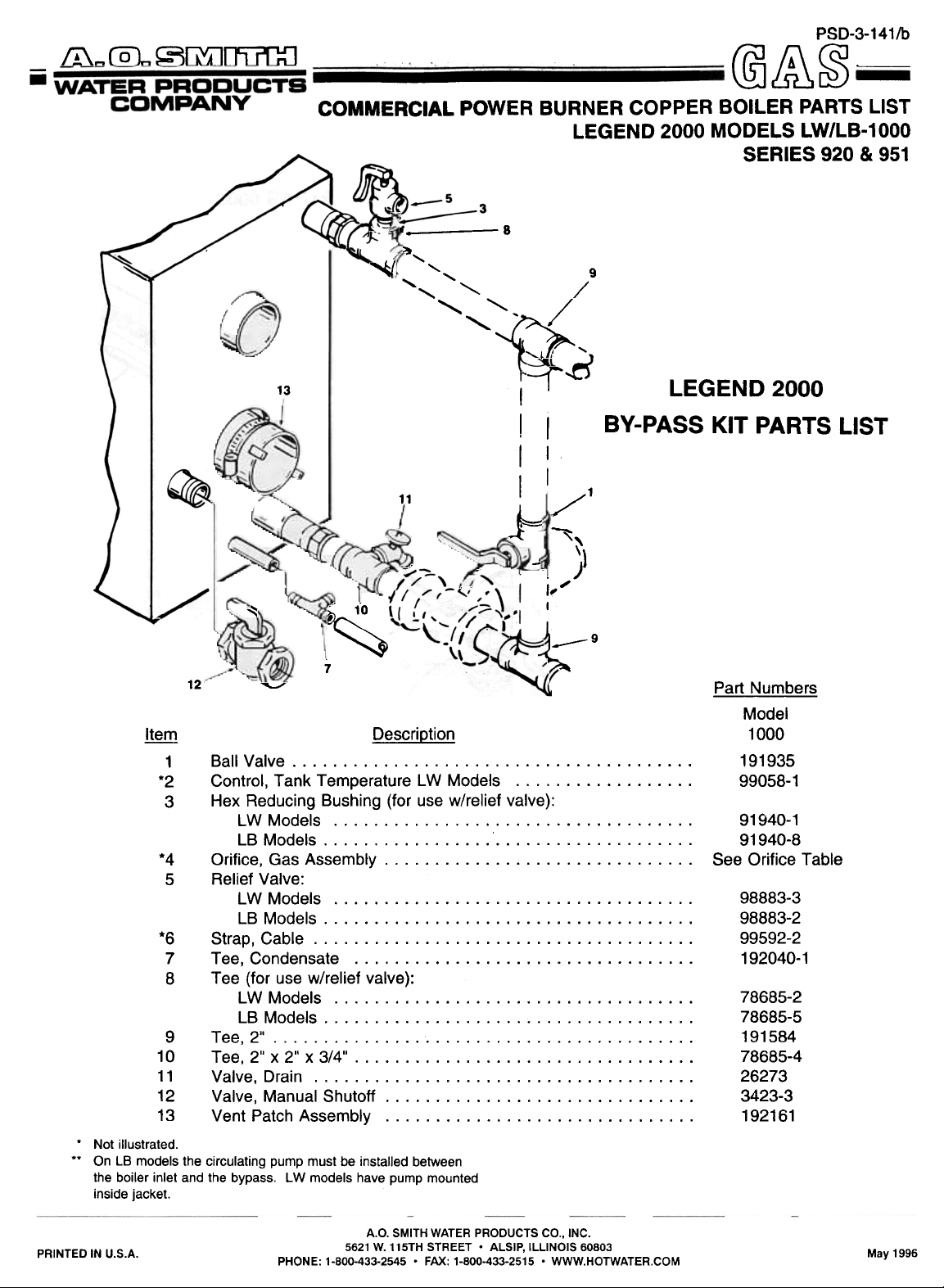
COMMERCIAL POWER BURNER COPPER BOILER PARTS LIST
LEGEND 2000 MODELS LW/LB-1000
SERIES 920 & 951
~ -8
~
"
~
"
"
"
, /
~
~J/ --r~
/
13
11
~
~
12
.,..::;,,'
~
Ball Valve. . . . . . . . . . . . . . . . . . . . . . . . . . . . . . . . . . . . . . . .
1
*2
*4
*6
10
11
12
13
Control, Tank Temperature LW Models. . . . . . . . . . . . . . . . . .
Hex Reducing Bushing (for use w/relief valve):
3
LWModels LBModels Orifice, Gas Assembly Relief Valve:
5
LWModels LB Models. . . . . . . . . . . . . . . . . . . . . . . . . . . . . . . . . . . . .
Strap, Cable Tee, Condensate. . . . . . . . . . . . . . . . . . . . . . . . . . . . . . . . . .
7
Tee (for use w/relief valve):
8
LW Models. . . . . . . . . . . . . . . . . . . . . . . . . . . . . . . . . . . .
LBModels Tee, 2" . . . . . . . . . . . . . . . . . . . . . . . . . . . . . . . . . . . . . . . . . .
9
Tee,2"x2"x3/4" Valve, Drain Valve, Manual Shutoff. . . . . . . . . . . . . . . . . . . . . . . . . . . . . . .
Vent Patch Assembly. . . . . . . . . . . . . . . . . . . . . . . . . . . . . . .
. Not illustrated.
.. On LB models the circulating pump must be installed between
the boiler inlet and the bypass. LW models have pump mounted
inside jacket.
7
Description
I
I
I
I
I
I
I
./1
~
-,..
j
I '
1-,
I."
I
BY-PASS KIT PARTS LIST
'"
)"1 )
LEGEND 2000
1--9
~
Part Numbers
Model
1000
191935
99058-1
91940-1
91940-8
See Orifice Table
98883-3
98883-2
99592-2
192040-1
78685-2
78685-5
191584
78685-4
26273
3423-3
192161
A.O. SMITH WATER PRODUCTS CO., INC.
PRINTED IN U.S.A. May 1996
~9~
~~~
~
PHONE: 1-800-433-2545 . FAX: 1-800-433-2515 . WWW.HOTWATER.COM
5621 W. 115TH STREET. ALSIP, ILLINOIS 60803
Page 3

Page 4
LEGEND 2000 PARTS LIST A
~
Bracket, Cover BurnerandConeAssembly Bushing, Temp. Sensing. . . . . . . . . . . . . . . . . . . . . . . . . . . . .
1
2
3
4
Combustion Chamber Assembly Connector, Hose. . . . . . . . . . . . . . . . . . . . . . . . . . . . . . . . . . .
5
Control, Dual Limit (for LB) ,...,..,..,..."."..,.".,
6
Control, Dual Limit (for LW) Coupling, Flexiblew/Gasket Cover. . . . . . . . . . . . . . . . . . . . . . . . . . . . . . . . . . . . . . . . . . .
7
8
9
10
11
12
13
14
15
16
17
18
19
20
21
22
23
24
25
25
26
27
28
29
30
Gasket, Outer. . . . . . . . . . . . . . . . . . . . . . . . . . . . . . . . . . . . .
Gasket,PlateAssembly Gasket, Inner. . . . . . . . . . . . . . . . . . . . . . . . . . . . . . . . . . . . .
HousingAssembly Igniter. . . . . . . . . . . . . . . . . . . . . . . . . . . . . . . . . . . . . . . . . .
Insulation, Burner Nut, Manifold. . . . . . . . . . . . . . . . . . . . . . . . . . . . . . . . . . . . .
O-Ring. . . . . . . . . . . . . . . . . . . . . . . . . . . . . . . . . . . . . . . . . .
Power Supply, Temperature Indicator. . . . . . . . . . . . . . . . . . . .
Screw, Machine #8-32 SST . . . . . . . . . . . . . . . . . . . . . . . . . . .
Sealer,Silicone Sensor, Temperature w/Temperature Indicator. . . . . . . . . . . . .
Spacer, Ring Switch, Safety Flow. . . . . . . . . . . . . . . . . . . . . . . . . . . . . . . . .
TeeAssembly Tube Assembly, Primary (LW Models) Tube Assembly, Primary (LB Models) . . . . . . . . . . . . . . . . . . . .
Tube Assembly, Outlet Tube Assembly, Secondary ,."..., ", , Washer, Flat #8 SST . . . . . . . . . . . . . . . . . . . . . . . . . . . . . . . .
Well,TemperatureSensor Restrictor Air, Top Cover. . . . . . . . . . . . . . . . . . . . . . . . . . . . .
Description
Part Numbers
Model
1000
191602
191850-2
191908
192129
191765
191671
191671-1
191780-1
192155
191563-1
191564-1
191563
191627-4
192334
191618
191555-1
191556-2
191905
191770
191482-1
191910
191554-1
78168
192387
192388
192225
192224
192386
191768
191907
191926-1
3
Page 5

Page 6

LEGEND 2000 PARTS LIST B
~
Block,Terminal(4Required) , Bolt,Machine5/16"-18 Box4"x4" Junction Bracket Assembly, Front Bracket, Dia-Scan ... . . . . . . . . . . . . . . . . . . . . . . . . . . . . . . . .
1
2
3
4
5
6
Cover, Top Dia-ScanAssembly Fastener FrameAssembly Handle, Lower Front Panel. . . . . . . . . . . . . . . . . . . . . . . . . . . .
7
8
9
10
Indicator, Temperature. . . . . . . . . . . . . . . . . . . . . . . . . . . . . . . .
11
Label, Control Panel. . . . . . . . . . . . . . . . . . . . . . . . . . . . . . . . .
12
Nut, Hex #8-32 . . . . . . . . . . . . . . . . . . . . . . . . . . . . . . . . . . . . .
13
14
Nut,Hex5/16"-18 Overlay,On/Off Panel, Left Side , Panel, Lower Front Panel, Rear. . . . . . . . . . . . . . . . . . . . . . . . . . . . . . . . . . . . . . .
15
16
17
18
Panel, Right Side Panel, Upper Front. . . . . . . . . . . . . . . . . . . . . . . . . . . . . . . . . .
19
20
21
Plate,On/Off Power Supply, Temperature Indicator. . . . . . . . . . . . . . . . . . . . .
22
23
Retainer,Wire Screw, Flat Head #4 Screw #10, Ground ." , ,..,..,.."...".
24
25
Screw, Thread Cut #8 x 5/8" Switch, Rocker. . . . . . . . . . . . . . . . . . . . . . . . . . . . . . . . . . . . .
26
27
Transformer, 50VA Trim Washer, Lock #10 . . . . . . . . . . . . . . . . . . . . . . . . . . . . . . . . . . .
28
29
30
Washer, Lock #8 . . . . . . . . . . . . . . . . . . . . . . . . . . . . . . . . . . . .
31
Washer, Flat 5/16"
32
Description
Part Numbers
Model
1000
98205
191358-1
93558-4
192167
191756
191609-1
191815
191813
192127
191802
191910
191852-1
41284-1
097896
191799
192187
191805-1
192191
192186
191806-1
191800
191905
39884
191906
39885-1
20107-3
191665
192337
191810
191771-1
3347-1
191359
5
Page 7

Page 8

LEGEND 2000 PARTS LIST C
~
1
Clamp, Hose (Large) . . . . . . . . . . . . . . . . . . . . . . . . . . . . . . . .
2
Clamp, Hose (Small) . . . . . . . . . . . . . . . . . . . . . . . . . . . . . . . .
3
Connector,FemaleBulkhead Connector, Port. . . . . . . . . . . . . . . . . . . . . . . . . . . . . . . . . . .
4
5
Drain, Flange. . . . . . . . . . . . . . . . . . . . . . . . . . . . . . . . . . . . .
6
Drain,FlangeAssembly Elbow. . . . . . . . . . . . . . .!. . . . . . . . . . . . . . . . . . . . . . . . . . . .
7
8
Gasket, Blocked Flue Gasket, Drain. . . . . . . . . . . . . . . . . . . . . . . . . . . . . . . . . . . . .
9
10
11
12
13
14
15
16
17
18
19
20
21
22
23
24
25
26
27
28
29
30
31
Gasket, Vent. . . . . . . . . . . . . . . . . . . . . . . . . . . . . . . . . . . . .
Nipple. . . . . . . . . . . . . . . . . . . . . . . . . . . . . . . . . . . . . . . . . .
Nut, Hex 1/4" Nut,Hex1/4"Stainless O-Ring. . . . . . . . . . . . . . . . . . . . . . . . . . . . . . . . . . . . . . . . . .
Plate, Drain Seal. . . . . . . . . . . . . . . . . . . . . . . . . . . . . . . . . . .
Pump Assembly, Circulator (LW Models Only) Tube Assembly, Inlet. . . . . . . . . . . . . . . . . . . . . . . . . . . . . . . .
Tube Assembly, Primary (LB Models) . . . . . . . . . . . . . . . . . . . .
Tube Assembly, Primary (LW Models) Tubing, Condensate. . . . . . . . . . . . . . . . . . . . . . . . . . . . . . . .
Tubing, Pressure. . . . . . . . . . . . . . . . . . . . . . . . . . . . . . . . . .
U-BoltAssembly Valve, Drain. . . . . . . . . . . . . . . . . . . . . . . . . . . . . . . . . . . . . .
Vent,Assembly Vent, Flange Vent, Flange Assembly Washer,Lock1/4"Stainless Washer, Flat. . . . . . . . . . . . . . . . . . . . . . . . . . . . . . . . . . . . . .
Washer, Lock 1/4" . . . . . . . . . . . . . . . . . . . . . . . . . . . . . . . . . .
Bracket, Vent Support. . . . . . . . . . . . . . . . . . . . . . . . . . . . . . .
Vent, Restricting Ring (Series 951, LP) . . . . . . . . . . . . . . . . . .
DescriDtion
Part Numbe!:§
Model
1000
191794-1
191794
191744
191745
191620
191625
191664
191767
191622
191683-1
20373-18
170272
191769
191556-1
191626
192203
192308
192225
192388
191746
191562
191938
26273
191687-1
191685-2
191686-1
191771
191766
1006
192194
191923-1
7
Page 9

Page 10

LEGEND 2000 PARTS LIST D
~
20
21
22
23
24
25
26
27
28
29
30
31
32
33
34
35
36
37
38
39
40
41
42
43
Blower. . . . . . . . . . . . . . . . . . . . . . . . . . . . . . . . . . . . . . . . . .
2
BlowerAdapterAssembly BlowerManifoldAssembly Bracket, Blower Clamp, Hose Elbow,11/4" Elbow,Union11/4" Flange, Observation Port Gasket, Blower Air Inlet. . . . . . . . . . . . . . . . . . . . . . . . . . . . . .
3
4
5
6
7
8
9
10
11
12
13
14
15
16
17
18
19
Gasket, Burner. . . . . . . . . . . . . . . . . . . . . . . . . . . . . . . . . . . .
Gasket, Manifold. . . . . . . . . . . . . . . . . . . . . . . . . . . . . . . . . . .
Gasket, Port (1/8" Thick) Gasket, Port (1/16" Thick) Manifold Assembly. . . . . . . . . . . . . . . . . . . . . . . . . . . . . . . . .
Nipple, Close 1/8" . . . . . . . . . . . . . . . . . . . . . . . . . . . . . . . . . .
Nipple, Close Stainless. . . . . . . . . . . . . . . . . . . . . . . . . . . . . .
Nipple, Tapped. . . . . . . . . . . . . . . . . . . . . . . . . . . . . . . . . . . .
Nipple,11/4"x381/2" Nipple,11/4"x283/4" Nipple,11/4"x2" Nipple, 1 1/4" x 3" . . . . . . . . . . . . . . . . . . . . . . . . . . . . . . . . . .
Nipple,11/4"x4" Nut, Hex 1/4" Orifice, Air (Series 920 - Natural Gas) . . . . . . . . . . . . . . . . . . . .
Orifice, Air (Series 951 - Liquid Propane Gas) """"""'"
Orifice,Union Plug, 1/8" Pipe Port, Observation Lower Port, Observation Upper Screen, Air Inlet. . . . . . . . . . . . . . . . . . . . . . . . . . . . . . . . . . .
Screw, Cap 1/4" Screw, Flathead #8-32 x 1/2" Screw, Flathead #8-32 x 3/4" . . . . . . . . . . . . . . . . . . . . . . . . . .
Switch, Low Gas Pressure. . . . . . . . . . . . . . . . . . . . . . . . . . . .
Switch,RestrictedGasFlow Tee, 1/8" Tee, Union. . . . . . . . . . . . . . . . . . . . . . . . . . . . . . . . . . . . . . .
Tubing, Pressure. . . . . . . . . . . . . . . . . . . . . . . . . . . . . . . . . .
Tubing, Top Cover Assembly. . . . . . . . . . . . . . . . . . . . . . . . . .
U-BoltAssembly Valve, Main Gas. . . . . . . . . . . . . . . . . . . . . . . . . . . . . . . . . . .
Valve, Manual Shutoff Valve, Solenoid Gas Washer,Lock1/4"
Description
Part Numbers
Model
1000
192195
192215-1
192217
192223
191794
192216
86506-1
191573
192213
191564
191565
191576-1
191576
192309
191147-1
191772-1
86505-26
86505-28
86505-27
86505
86505-2
86505-6
170272
192270-1
192270-3
See Orifice Table
3348
191572
191572-1
192220-1
190960-2
191542
191542-1
191149-1
191076
40119
191633
191562
191925
191938-3
078481-3
3423-3
192189
1006
9
Page 11

lte.rn
LEGEND 2000 PARTS LIST E
Descrigtion
Model
~
10
11
12
13
14
15
16
17
18
1
2
3
4
5
6
7
8
9
Valve, Main Gas, LP 951 Series Regulator, LP 951 Series Valve, Manual Shut-off Switch, Restricted Flow Switch, Low Pressure Nipple, 1 1/4" Nipple. 1 1/4" Nipple, 1 1/4" Elbow, Union 1 1/4" Elbow, 90° Street 1 1/4" Elbow, 90° 1 1/4" Nipple, 1 1/4" Nipple, 1 1/4" Nipple, 1 1/4" ."""""""".'.'..""..'..'..'.'.'."
Tee, 1/8" NPT Branch Connector, Angle 1/8" .'."'..'..'.'..'."."...'.
Bleeder, Tube .""".'.."""."'..'..' '.'.'..'..
Bleeder, Tube
,
"."".""..."",.,..,..
'.'.""."".'..'.".".'.'
'."'..".".".""."..'"
, ,
,
077780-0
192460
3423-3
191076
191149-3
86505-13
86505-2
86505-10
86506
94516
192216
86505-32
86505-6
86505-4
192465
1578
210016
192461
LW/LB 1000
SERIES 951
11
CANADA/USA
LIQUID PROPANE GAS
c~ ~ o. "'"
6
18
5/"'00
1
13
/
4
11
3
~
15
14~
~
,,/
~
r7'
7
- ~
17
14
I
16
.10
2
!~
7
1
/
"S
9
Page 12

LEGEND 2000 PARTS LIST F
Part Numbers
Model
~
1
Bushing,Snap(Large,11/8"Hole) Bushing, Snap (Small,7/8" Hole) Cabinetw/Cover Control, Hot Surface Ignition FUS8,1/4Arnp Fuse. 2 Amp . . . . . . . . . . . . . . . . . . . . . . . . . . . . . . . . . . . . . .
Descriotion
2
3
4
5
6
7
Fuse,10ArT1) Holder, Fuse. . . . . . . . . . . . . . . . . . . . . . . . . . . . . . . . . . . . . .
8
9
Module,lnterfaceAssembly Nut, Hex #10 PaneIAssernbly Relay,S.P.D.T.(120Vac) Relay,S.P.D.T.(24Vac) Relay,D.P.S.T.(120Vac) Screw, Thread Cut #8 x 3/8" Screw, Thread Cut #8 x 5/8" Spacer, Unified Strip, Terminal. . . . . . . . . . . . . . . . . . . . . . . . . . . . . . . . . . . .
10
11
12
13
14
15
16
17
18
19
Switch,BlockedFlue Switch,BlowerProverSwitch TabCapTerminal Tubing, Pressure Washer,Lock#10 ,
20
21
22
23
..1Q.Q2-
191078
98863
191561
191848
191842-2
191842
191842-1
191843
191757
7207
191678
191661
191662
191880
20107
20107-3
191946
191656
191667
191666
170053
. 191562
. 3347
11
Page 13

LEGEND 2000 ORIFICE TABLE
LW/LB-1000
MODEL
PART NUMBER
L W/LB 1000
I LW/LB 1000
I LW/LB 1000
I LW/LB 1000
* Factory installed orifice.
WIRE (SOLID COLORS)
WIRI
WHI'fB
BLACK
BROW.
YBLLOW
RBD
GRBB.
WHI'fB
BLACK
WHI'fB
BLACK
BLUB
GAUGB
18
18
18
18
18
1.
16
16
1.
1.
18
NATURAL
*192222-0
192222-1
192222-2
A.O.S. P~R'r 10.
170595
170596
170890
170604
170603
041972
086580
086578
041974
099650
191719
PROPANE
PART NUMBER
*192739-0
192739-1
192139-2
(Use dash no. after part no. to Indicate length of
wire required in inches.)
Example: Green, #14 gauge, 20" in length
A. O. S. part no. 041972-020.
SIZE
~
0.555
0.537
0.533
0.333
0.329
0.325
ELEVATION
(FT.)
0-2000
2001-3000
3001-4000
0-2000
2001-3000
3001-4000
WIRS
BLACK with WHITS
BLACK with RSD
BLACK with YSLLOW
BLACK with BLUE
BLACK with GREEK
WHIT. with BLACK
WHIT. with RED
WHIT. with GRESN
WHIT. with YELLOW
WHIT. with BROWN
WHITS with BLUS
WHIT. with VIOLET
YSLLOW with RED
YSLLOW with BLACK
(Use dash no. after part no. to indicate lengtl. of wire required in inches.)
Example: Yellow with brown stripe A. O. S. part no. 191710-020 20" in length.
WIRE (STRIPED COLORS, #18 GAUGE)
A.O.S. PART MO.
19169.
191695
191696
191697
191698
191699
191700
191701
191702
191703
19170.
191705
191706
191707
YELLOW with BLUI
YELLOW with VIOLET
YELLOW with BROWI
YELLOW with GREIM
BLUI with WHITE
BLUE with YILLOW
RED with YELLOW
WIRE
BLUI with RID
RED with WHITI
RID with GRill
_.P:I) wi th BLU~
A.O.S. PAR'r 10.
191188
191789
191718
191111
191712
191713-
19171.
191715
191716
191717
191718
W.P.C. PART NO. 192305 REV. 2
~
~
 Loading...