

A.O. Smith GDVT, GDV User Manual
Instruction Manual
RESIDENTIAL GAS WATER HEATERS
DIRECT VENT GAS MODELS GDV/GDVT
NOT FOR USE IN MANUFACTURED (MOBILE) HOMES
A DIVISION OF A. O. SMITH CORPORATION
Ashland City, TN 37015
www.hotwater.com
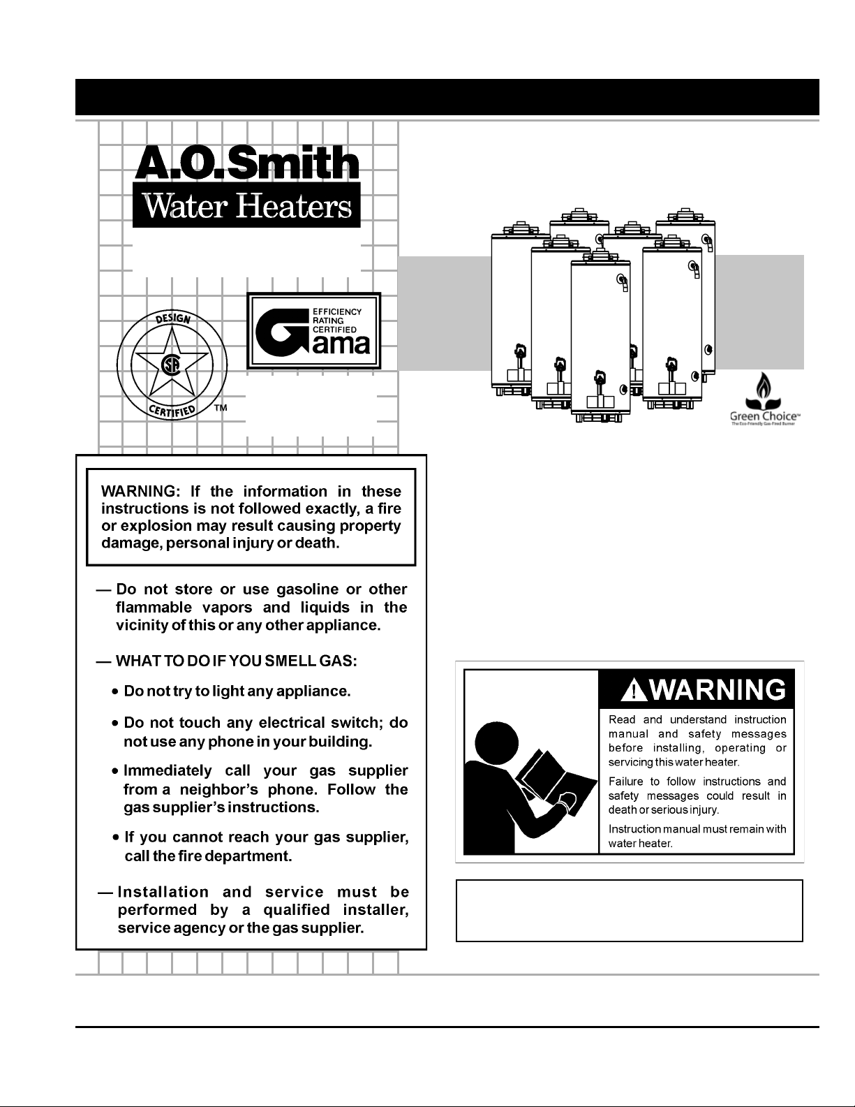
GAMA certifi cation applies to
all residential gas water heaters with capacities of 20 to
100 gallons with input rating
of 75,000 BTU/Hr. or less.
• For Your Safety •
AN ODORANT IS ADDED TO THE GAS USED
BY THIS WATER HEATER.
ALL TECHNICAL AND WARRANTY QUESTIONS: SHOULD BE DIRECTED TO THE LOCAL DEALER FROM WHOM THE WATER
HEATER WAS PURCHASED. IF YOU ARE UNSUCCESSFUL, PLEASE WRITE TO THE COMPANY LISTED ON THE RATING
PLATE ON THE WATER HEATER.
KEEP THIS MANUAL IN THE POCKET ON HEATER FOR FUTURE REFERENCE
WHENEVER MAINTENANCE ADJUSTMENT OR SERVICE IS REQUIRED.
PRINTED IN CANADA 1107 PART NO. 186138-000
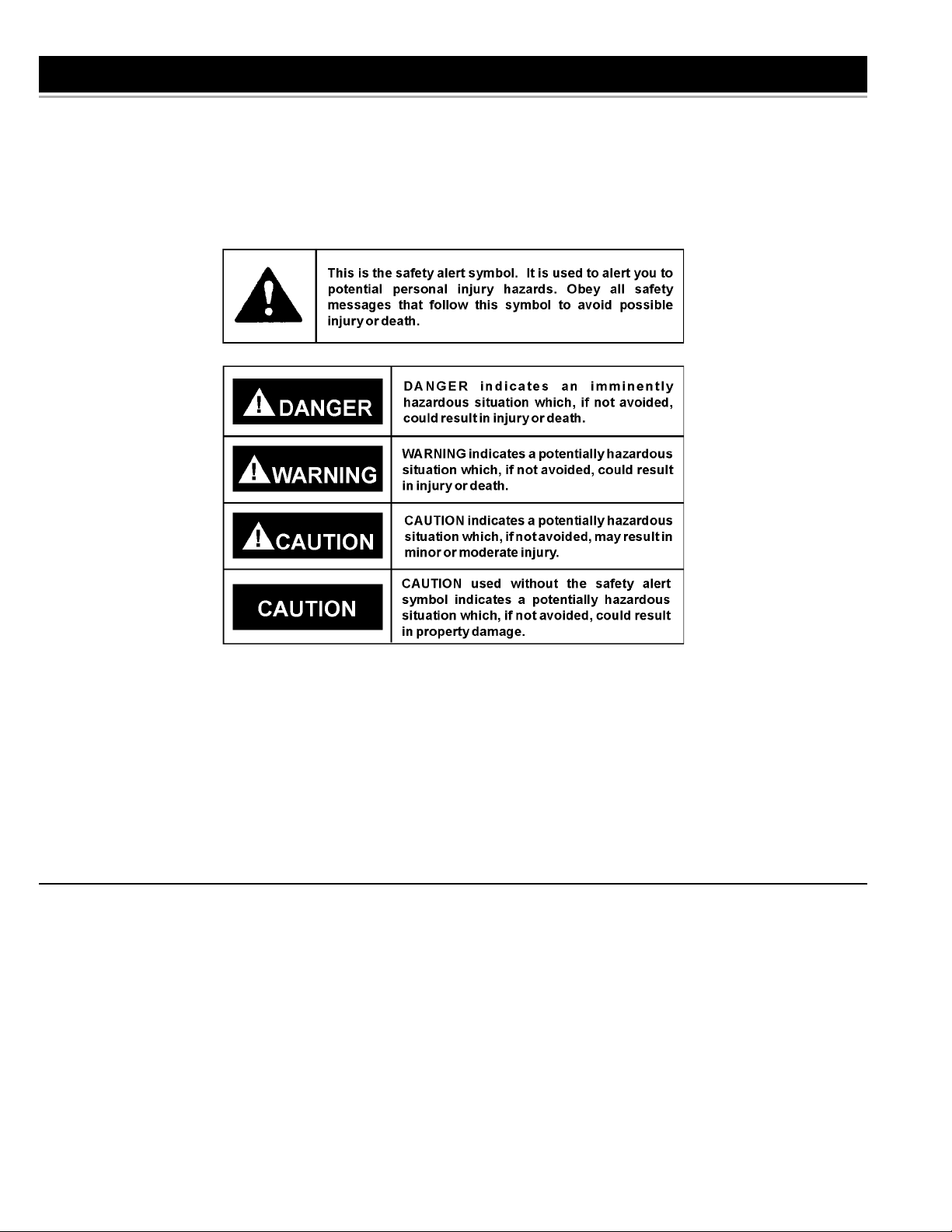
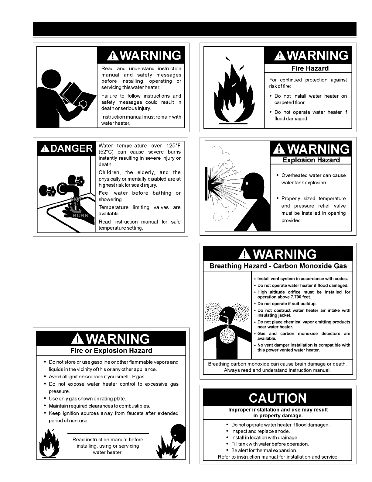
SAFE INSTALLATION, USE AND SERVICE
Your safety and the safety of others is extremely important in the installation, use and servicing of this water heater.
Many safety-related messages and instructions have been provided in this manual and on your own water heater to warn
you and others of a potential injury hazard. Read and obey all safety messages and instructions throughout this manual. It
is very important that the meaning of each safety message is understood by you and others who install, use or service this
water heater.
All safety messages will generally tell you about the type of hazard, what can happen if you do not follow the safety message
and how to avoid the risk of injury.
The California Safe Drinking Water and Toxic Enforcement Act requires the Governor of California to publish a
list of substances known to the State of California to cause cancer, birth defects, or other reproductive harm,
and requires businesses to warn of potential exposure to such substances.
WARNING: This product contains a chemical known to the State of California to cause cancer, birth defects, or
other reproductive harm. This appliance can cause low-level exposure to some of the substances included in
the Act.
IMPORTANT DEFINITIONS
• Qualifi ed Installer: A qualifi ed installer must have ability equivalent to a licensed tradesman in the fi elds of plumbing,
air supply, venting and gas supply, including a thorough understanding of the requirements of the National Fuel Gas
Code as it relates to the installation of gas fi red water heaters. The qualifi ed installer must also be familiar with the
design features and use of fl ammable vapor ignition resistant water heaters, and have a thorough understanding of this
instruction manual.
• Service Agency: A service agency also must have ability equivalent to a licensed tradesman in the fi elds of plumbing,
air supply, venting and gas supply, including a thorough understanding of the requirements of the National Fuel Gas Code
as it relates to the installation of gas fi red water heaters. The service agency must also have a thorough understanding
of this instruction manual, and be able to perform repairs strictly in accordance with the service guidelines provided by
the manufacturer.
• Gas Supplier: The Natural Gas or Propane Utility or service who supplies gas for utilization by the gas burning
appliances within this application. The gas supplier typically has responsibility for the inspection and code approval of
gas piping up to and including the Natural Gas meter or Propane storage tank of a building. Many gas suppliers also
offer service and inspection of appliances within the building.
2
GENERAL SAFETY
3

TABLE OF CONTENTS
SAFE INSTALLATION, USE AND SERVICE . . . . . . . . . . . . . 2
GENERAL SAFETY . . . . . . . . . . . . . . . . . . . . . . . . . . . . . . . . 3
TABLE OF CONTENTS . . . . . . . . . . . . . . . . . . . . . . . . . . . . . 4
INTRODUCTION . . . . . . . . . . . . . . . . . . . . . . . . . . . . . . . . . . . 4
Preparing for the installation . . . . . . . . . . . . . . . . . . . . . . . 4
INSTALLATION REQUIREMENTS FOR THE
COMMONWEALTH OF MASSACHUSETTS . . . . . . . . . . . . . 5
TYPICAL INSTALLATION . . . . . . . . . . . . . . . . . . . . . . . . . . . . 6
Get to know your water heater . . . . . . . . . . . . . . . . . . . . . 6
Replacement parts . . . . . . . . . . . . . . . . . . . . . . . . . . . . . . . 6
Mixing valve useage . . . . . . . . . . . . . . . . . . . . . . . . . . . . . 7
LOCATING THE NEW WATER HEATER . . . . . . . . . . . . . . . . 8
Facts to consider about location . . . . . . . . . . . . . . . . . . . . 8
Insulation blankets . . . . . . . . . . . . . . . . . . . . . . . . . . . . . . . 9
Ventilation for appliances located in confi ned spaces . . . . 9
Vent termination . . . . . . . . . . . . . . . . . . . . . . . . . . . . . . . . . 9
INSTALLING THE NEW WATER HEATER . . . . . . . . . . . . 10-18
Required ability . . . . . . . . . . . . . . . . . . . . . . . . . . . . . . . . 10
Inspect shipment . . . . . . . . . . . . . . . . . . . . . . . . . . . . . . . 10
General . . . . . . . . . . . . . . . . . . . . . . . . . . . . . . . . . . . . . . 10
Water piping . . . . . . . . . . . . . . . . . . . . . . . . . . . . . . . . . . . 10
T & P valve and pipe insulation (if supplied) . . . . . . . . . . .11
Temperature-pressure relief valve . . . . . . . . . . . . . . . . . . .11
Water (potable) heating and space heating . . . . . . . . . . . 12
Closed water system . . . . . . . . . . . . . . . . . . . . . . . . . . . . 12
Gas piping . . . . . . . . . . . . . . . . . . . . . . . . . . . . . . . . . . . . 12
Sediment traps . . . . . . . . . . . . . . . . . . . . . . . . . . . . . . . . . 14
Filling the water heater . . . . . . . . . . . . . . . . . . . . . . . . . . 14
Venting . . . . . . . . . . . . . . . . . . . . . . . . . . . . . . . . . . . . . . . 14
High altitude installations . . . . . . . . . . . . . . . . . . . . . . . . . 14
Combustion air and ventilation . . . . . . . . . . . . . . . . . . . . 15
Vent terminal clearances . . . . . . . . . . . . . . . . . . . . . . . . . 15
Vent connections . . . . . . . . . . . . . . . . . . . . . . . . . . . . . . . 16
Locating clearance hole for vent . . . . . . . . . . . . . . . . . . . 16
High rise vent arrangement . . . . . . . . . . . . . . . . . . . . . . . 16
Standard vent arrangement . . . . . . . . . . . . . . . . . . . . . . . 17
Securing vent termination assembly to the exterior wall . 17
Uncompressing the corrugated tubing . . . . . . . . . . . . . . . 17
Vent restricter plate . . . . . . . . . . . . . . . . . . . . . . . . . . . . . 17
Offset vent arrangement Condition 1 . . . . . . . . . . . . . . . . 18
Offset vent arrangement Condition 2 . . . . . . . . . . . . . . . . 18
LIGHTING & OPERATING LABEL . . . . . . . . . . . . . . . . . . . . 19
TEMPERATURE REGULATION . . . . . . . . . . . . . . . . . . . . . . 20
Temperature regulation . . . . . . . . . . . . . . . . . . . . . . . . . . 20
FOR YOUR INFORMATION . . . . . . . . . . . . . . . . . . . . . . .21-22
External damage . . . . . . . . . . . . . . . . . . . . . . . . . . . . . . . 21
Start up conditions . . . . . . . . . . . . . . . . . . . . . . . . . . . . . . 21
Condensate . . . . . . . . . . . . . . . . . . . . . . . . . . . . . . . . . . . 21
Smoke/odor . . . . . . . . . . . . . . . . . . . . . . . . . . . . . . . . . . . 21
Thermal expansion . . . . . . . . . . . . . . . . . . . . . . . . . . . . . 21
Strange sounds . . . . . . . . . . . . . . . . . . . . . . . . . . . . . . . . 21
Operational Conditions . . . . . . . . . . . . . . . . . . . . . . . . . . 21
Smelly water . . . . . . . . . . . . . . . . . . . . . . . . . . . . . . . . . . 21
“Air” in hot water systems . . . . . . . . . . . . . . . . . . . . . . . . 22
High water temperature shut off system . . . . . . . . . . . . . 22
MAINTENANCE . . . . . . . . . . . . . . . . . . . . . . . . . . . . . . . .23-25
Venting system inspection . . . . . . . . . . . . . . . . . . . . . . . . 23
Pilot and main burner . . . . . . . . . . . . . . . . . . . . . . . . . . . . 23
Temperature & pressure relief valve . . . . . . . . . . . . . . . . 24
Draining . . . . . . . . . . . . . . . . . . . . . . . . . . . . . . . . . . . . . . 24
Cathodic protection - anode . . . . . . . . . . . . . . . . . . . . . . . 24
Anode rod maintenance . . . . . . . . . . . . . . . . . . . . . . . . . . 24
Drain valve washer replacement . . . . . . . . . . . . . . . . . . . 25
LEAKAGE CHECKPOINTS . . . . . . . . . . . . . . . . . . . . . . . . . . 26
Service . . . . . . . . . . . . . . . . . . . . . . . . . . . . . . . . . . . . . . . 26
TROUBLESHOOTING GUIDELINES . . . . . . . . . . . . . . . . 27-28
NOTES . . . . . . . . . . . . . . . . . . . . . . . . . . . . . . . . . . . . . . . . . 29
WARRANTY . . . . . . . . . . . . . . . . . . . . . . . . . . . . . . . . . . . 30-31
INTRODUCTION
Thank You for purchasing this water heater. Properly installed
and maintained, it should give you years of trouble free service.
Abbreviations Found In This Instruction Manual:
• CSA - Canadian Standards Association
• ANSI - American National Standards Institute
• NFPA - National Fire Protection Association
• ASME - American Society of Mechanical Engineers
• GAMA - Gas Appliance Manufacturer’s Association
• UL - Underwriters Laboratories Inc.
This gas-fi red water heater is design certifi ed by Underwriters
Laboratories Inc. under American National Standard/CSA Standard for Gas Water Heaters ANSI Z21.10.1 • CSA 4.1 (current
edition).
PREPARING FOR THE INSTALLATION
1. Read the “General Safety” section, page 3 of this manual
fi rst and then the entire manual carefully. If you don’t follow
the safety rules, the water heater will not operate properly. It
could cause DEATH, SERIOUS BODILY INJURY AND/OR
PROPERTY DAMAGE. This manual contains instructions for
the installation, operation, and maintenance of the gas-fi red
water heater. It also contains warnings throughout the man-
ual that you must read and be aware of. All warnings and all
instructions are essential to the proper operation of the water
heater and your safety. Since we cannot put everything on
the fi rst few pages, READ THE ENTIRE MANUAL BEFORE
ATTEMPTING TO INSTALL OR OPERATE THE WATER
HEATER.
2. The installation must conform with these instructions and
the local code authority having jurisdiction. In the absence of
local codes, installations shall comply with the National Fuel
Gas Code ANSI Z223.1/NFPA. This publication is available
from the Canadian Standards Association, 8501 East Pleasant Valley Road, Cleveland, OH 44131.
3. If after reading this manual you have any questions or do not
understand any portion of the instructions, call the local gas
utility or the manufacturer whose name appears on the rating
plate.
4. Carefully plan the place where you are going to put the water
heater. Correct combustion, vent action, and vent pipe installation are very important in preventing death from possible
carbon monoxide poisoning and fi res, see Figures 1 and 2.
Examine the location to ensure the water heater complies
with the “Locating the New Water Heater” section in this
manual.
5. For California installation this water heater must be braced,
anchored, or strapped to avoid falling or moving during an
earthquake. See instructions for correct installation procedures. Instructions may be obtained from California Offi ce of
the State Architect, 400 P Street, Sacramento, CA 95814.
6. Massachusetts Code requires this water heater to be installed in accordance with Massachusetts 248-CMR 2.00:
State Plumbing Code and 248-CMR 5.00. For more information see next page.
4

INSTALLATION REQUIREMENTS FOR THE COMMONWEALTH OF MASSACHUSETTS
For all side wall terminated, horizontally vented power vent, direct vent, and power direct vent gas fueled water heaters installed
in every dwelling, building or structure used in whole or in part for residential purposes, including those owned or operated by the
Commonwealth and where the side wall exhaust vent termination is less than seven (7) feet above fi nished grade in the area of
the venting, including but not limited to decks and porches, the following requirements shall be satisfi ed:
INSTALLATION OF CARBON MONOXIDE DETECTORS At the time of installation of the side wall horizontal vented gas fueled equipment, the installing plumber or gasfi tter shall observe that a hard wired carbon monoxide detector with an alarm and
battery back-up is installed on the fl oor level where the gas equipment is to be installed. In addition, the installing plumber or
gasfi tter shall observe that a battery operated or hard wired carbon monoxide detector with an alarm is installed on each ad-
ditional level of the dwelling, building or structure served by the sidewall horizontal vented gas fueled equipment. It shall be the
responsibility of the property owner to secure the services of qualifi ed licensed professionals for the installation of hard wired
carbon monoxide detectors.
In the event that the side wall horizontally vented gas fueled equipment is installed in a crawl space or an attic, the hard wired
carbon monoxide detector with alarm and battery back-up may be installed on the next adjacent fl oor level.
In the event that the requirements of this subdivision can not be met at the time of completion of installation, the owner shall
have a period of thirty (30) days to comply with the above requirements provided that during said thirty (30) day period, a battery
operated carbon monoxide detector with an alarm shall be installed.
APPROVED CARBON MONOXIDE DETECTORS Each carbon monoxide detector as required in accordance with the above
provisions shall comply with NFPA 720 and be ANSI/UL 2034 listed and CSA certifi ed.
SIGNAGE A metal or plastic identifi cation plate shall be permanently mounted to the exterior of the building at a minimum height
of eight (8) feet above grade directly in line with the exhaust vent terminal for the horizontally vented gas fueled heating appliance or equipment. The sign shall read, in print size no less than one-half (1/2) inch in size, “GAS VENT DIRECTLY BELOW.
KEEP CLEAR OF ALL OBSTRUCTIONS.”
INSPECTION The state or local gas inspector of the side wall horizontally vented gas fueled equipment shall not approve the
installation unless, upon inspection, the inspector observes carbon monoxide detectors and signage installed in accordance with
the provisions of 248 CMR 5.08(2)(a) 1 through 4.
EXEMPTIONS: The following equipment is exempt from 248 CMR 5.08(2)(a)1 through 4:
1. The equipment listed in Chapter 10 entitled “Equipment Not Required To Be Vented” in the most current edition of NFPA 54
as adopted by the Board; and
2. Product Approved side wall horizontally vented gas fueled equipment installed in a room or structure separate from the dwelling, building, or structure used in whole or in part for residential purposes.
MANUFACTURER REQUIREMENTS - GAS EQUIPMENT VENTING SYSTEM PROVIDED When the manufacturer of Product
Approved side wall horizontally vented gas equipment provides a venting system design or venting system components with
the equipment, the instructions provided by the manufacturer for installation of the equipment and the venting system shall
include:
1. Detailed instructions for the installation of the venting system design or the venting system components; and
2. A complete parts list for the venting system design or venting system.
MANUFACTURER REQUIREMENTS - GAS EQUIPMENT VENTING SYSTEM NOT PROVIDED When the manufacturer of a
Product Approved side wall horizontally vented gas fueled equipment does not provide the parts for venting the fl ue gases, but
identifi es “special venting systems,” the following requirements shall be satisfi ed by the manufacturer:
1. The referenced “special venting system” instructions shall be included with the appliance or equipment installation
instructions; and
2. The “special venting systems” shall be Product Approved by the Board, and the instructions for that system shall include a
parts list and detailed installation instructions.
A copy of all installation instructions for all Product Approved side wall horizontally vented gas fueled equipment, all venting instructions, all parts lists for venting instructions, and/or all venting design instructions shall remain with the appliance or
equipment at the completion of the installation.
5
TYPICAL INSTALLATION
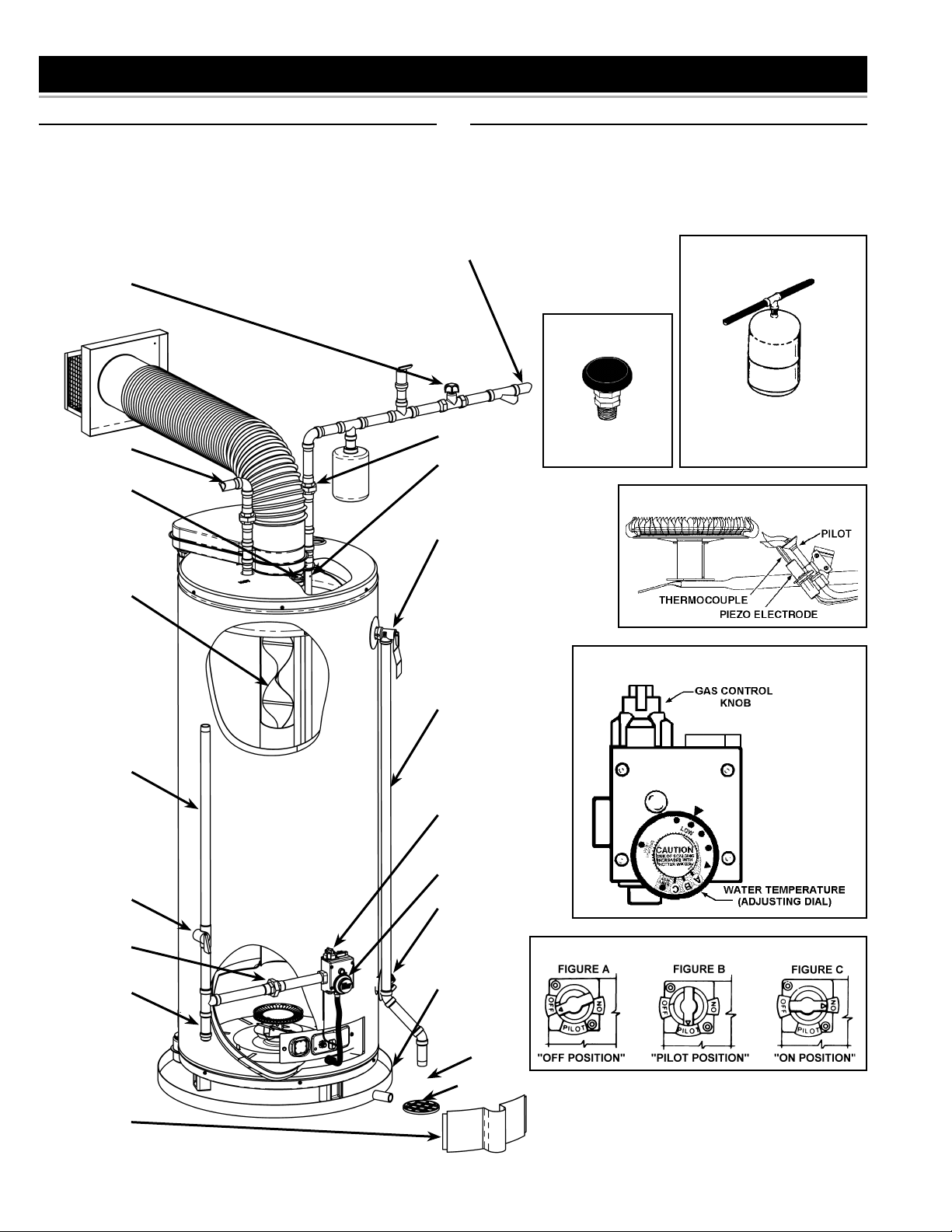
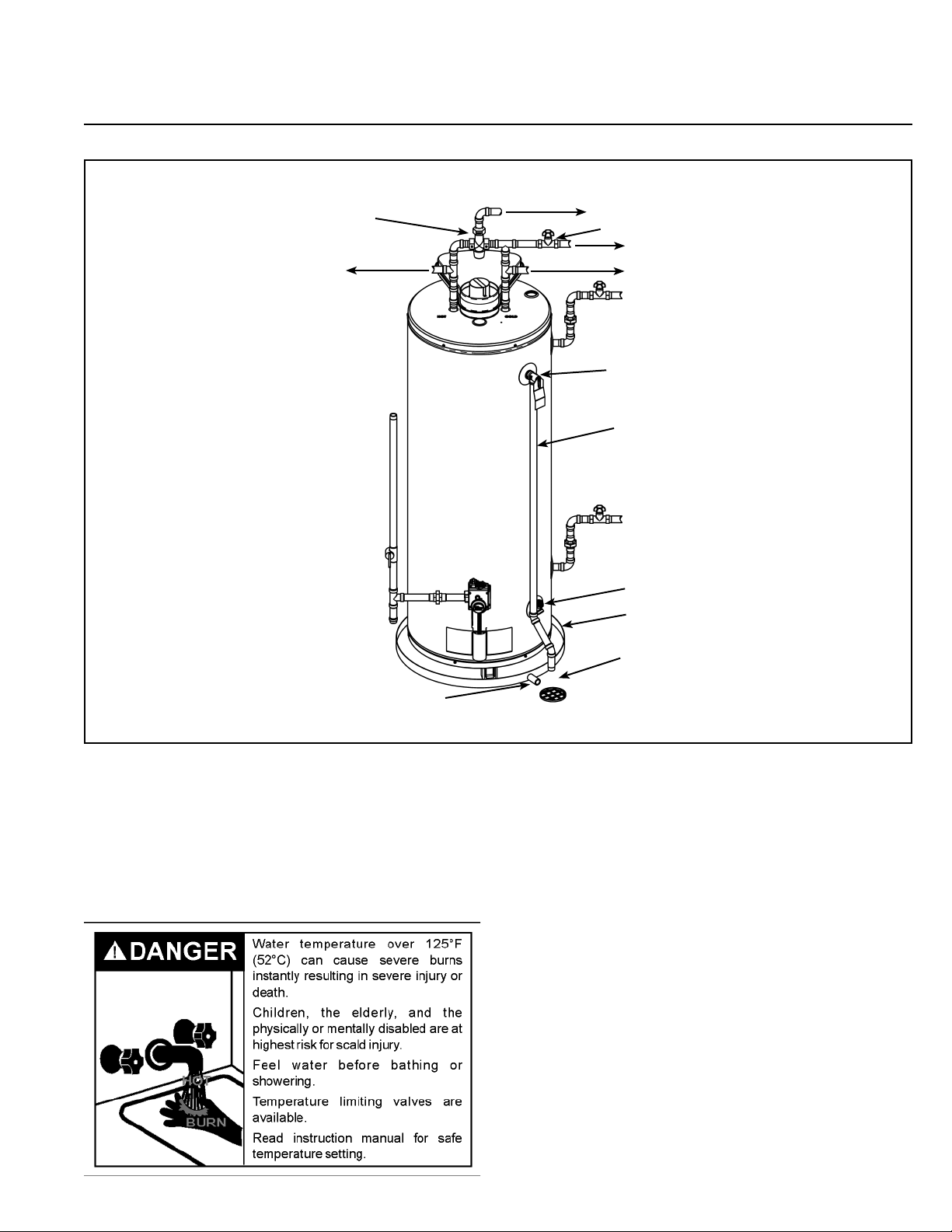
GET TO KNOW YOUR WATER HEATER REPLACEMENT PARTS
Replacement parts may be ordered through authorized servicers
or distributors. When ordering parts, provide complete model
and serial numbers (see rating plate), quantity and name of part
desired (as listed in Figure 1). Standard hardware items may be
purchased locally.
COLD WATER
INLET PIPE
INLET VALVE
VACUUM RELIEF
VALV E
HOT WATER
OUTLET PIPE
ANODE
UNION
INLET DIP
TUBE
TEMPERATURE
AND PRESSURE
RELIEF VALVE
INSTALL PER
LOCAL CODES.
THERMAL
EXPANSION TANK
INSTALL THERMAL EXPANSION
TANK IF WATER HEATER IS
INSTALLED IN A CLOSED
SYSTEM.
GAS PILOT & MAIN BURNER
FLUE BAFFLE
GAS SUPPLY
LINE
MAIN MANUAL
GAS SHUTOFF
VALV E
GROUND-JOINT
UNION
DIRT LEG
THERMOSTAT
DISCHARGE PIPE
(DO NOT CAP OR
PLUG)
GAS CONTROL
KNOB
WATER
TEMPERATURE
ADJUSTING DIAL
DRAIN VALVE
GAS CONTROL
DRAINPAN
6” MAXIMUM
AIR GAP
OUTER DOOR
ALL PIPING MATERIALS TO BE
SUPPLIED BY CUSTOMER.
FLOOR DRAIN
FIGURE 1
6
MIXING VALVE USAGE
NON-SCALD
TEMPERING VALVE
NON-TEMPERED WATER SUPPLY
SUGGESTED PIPING
ARRANGEMENT FOR
TOP CONNECTIONS
TEMPERED POTABLE WATER
SHUT-OFF VALVE
COLD WATER INLET
NON-TEMPERED WATER RETURN
TEMPERATURE-PRESSURE
RELIEF VALVE
GAS SUPPLY
DISCHARGE PIPE
(DO NOT CAP
OR PLUG)
CERTAIN MODELS ARE EQUIPPED WITH
SIDE PLUMBING CONNECTIONS FOR
SPACE HEATING. THE HOT AND COLD
FITTING ASSEMBLIES (PART # 9001262)
CAN BE ORDERED THROUGH THE
MANUFACTURER.
DRAIN VALVE
DRAIN PAN
6” MAXIMUM
AIR GAP
TO SUITABLE DRAIN
FIGURE 2
This appliance has been design certifi ed as complying with
American National Standard/CSA Standard for water heaters
and is considered suitable for:
Water (Potable) Heating and Space Heating: All models are
considered suitable for water (potable) heating and space heating.
HOTTER WATER CAN SCALD:
Water heaters are intended to produce hot water. Water heated
to a temperature which will satisfy space heating, clothes washing, dish washing, and other sanitizing needs can scald and
permanently injure you upon contact. Some people are more
likely to be permanently injured by hot water than others. These
include the elderly, children, the infi rm, or physically/mentally
handicapped. If anyone using hot water in your home fi ts into
one of these groups or if there is a local code or state law requiring a certain temperature water at the hot water tap, then you
must take special precautions. In addition to using the lowest
possible temperature setting that satisfi es your hot water needs,
a means such as a *Mixing Valve, should be used at the hot
water taps used by these people or at the water heater. Mixing valves are available at plumbing supply or hardware stores.
Consult a Qualifi ed Installer or Service Agency. Follow mixing
valve manufacturer’s instructions for installation of the valves.
Before changing the factory setting on the thermostat, read the
“Temperature Regulation” section in this manual.
7
LOCATING THE NEW WATER HEATER
FACTS TO CONSIDER ABOUT THE LOCATION
Carefully choose an indoor location for the new water heater,
because the placement is a very important consideration for the
safety of the occupants in the building and for the most economical use of the appliance. This water heater is not for use in
manufactured (mobile) homes or outdoor installation.
Whether replacing an old water heater or putting the water heater
in a new location, the following critical points must be observed:
1. Select a location indoors as close as practical to the vent
terminal or location to which the water heater vent piping is
going to be connected, and as centralized with the water piping system as possible.
2. Selected location must provide adequate clearances for servicing and proper operation of the water heater.
• Sensors mounted in the drain pan that turn off the water supply to the entire home when water is detected in the drain
pan.
• Water supply shut-off devices that activate based on the water pressure differential between the cold water and hot water
pipes connected to the water heater.
• Devices that will turn off the gas supply to a gas water heater
while at the same time shutting off its water supply.
Also, the water heater must be located and/or protected so it is
not subject to physical damage by a moving vehicle.
Installation of the water heater must be accomplished in such a
manner that if the tank or any connections should leak, the fl ow
will not cause damage to the structure. For this reason, it is not
advisable to install the water heater in an attic or upper fl oor.
When such locations cannot be avoided, a suitable drain pan
should be installed under the water heater. Drain pans are available at your local hardware store. Such a drain pan must have
a minimum length and width of at least 2 in. (51mm) greater that
the water heater dimensions and must be piped to an adequate
drain. The pan must not restrict combustion air fl ow.
Water heater life depends upon water quality, water pressure
and the environment in which the water heater is installed. Water
heaters are sometimes installed in locations where leakage may
result in property damage, even with the use of a drain pan piped
to a drain. However, unanticipated damage can be reduced or
prevented by a leak detector or water shut-off device used in
conjunction with a piped drain pan. These devices are available
from some plumbing supply wholesalers and retailers, and detect and react to leakage in various ways:
• Sensors mounted in the drain pan that trigger an alarm or
turn off the incoming water to the water heater when leakage
is detected.
This water heater must not be installed directly on carpeting.
Carpeting must be protected by metal or wood panel beneath
the appliance extending beyond the full width and depth of the
appliance by at least 3 in. (76mm) in any direction, or if the appliance is installed in an alcove or closet, the entire fl oor must be
covered by the panel. Failure to heed this warning may result
in a fi re hazard.
8
INSULATION BLANKETS
Insulation blankets available to the general public for external use
on gas water heaters are not necessary with this product. The
purpose of an insulation blanket is to reduce the standby heat
loss encountered with storage tank water heaters. Your Water
heater meets or exceeds the National Appliance Energy Conservation Act standards with respect to insulation and standby loss
requirements, making an insulation blanket unnecessary.
Confi ned Space is a space whose volume is less than 50 cubic
feet per 1,000 Btu per hour (4.8 cm per kW) of the aggregate
input rating of all appliances installed in that space.
VENT TERMINATION
Before installing water heater determine placement of vent termination.
Make certain to observe vent location limitation, see Figures 3,
4 & 11.
Minimum clearances between the water heater
and combustible and noncombustible construction are: 0 in.
(0mm) from sides, 0 in. (0mm) from back, 4 in. (102mm) from
front of jacket to closet door and 20 in. (508mm) from top of
jacket to combustible and noncombustible material. Minimum
vent clearance: 1 in. (25mm)*. Provide 3 ft. (915mm) front clearance for servicing and adequate clearance between the jacket
top & ceiling for servicing the fl ue area, see Figure 4.
Should you choose to apply an insulation blanket to this heater,
you should follow these instructions (See Figure 1 for identifi ca-
tion of components mentioned below). Failure to follow these
instructions can restrict the air fl ow required for proper combus-
tion, resulting in fi re, asphyxiation, serious personal injury or
death.
• Do not cover the outer door, thermostat or temperature &
pressure relief valve.
• Do not cover the instruction manual. Keep it on the side of
the water heater or nearby for future reference.
• Do obtain new warning and instruction labels from the manufacturer for placement on the blanket directly over the existing labels.
* Where the wall is combustible and the wall thickness is over
14 in. (356mm), 1 in. (25mm) clearance to combustible materials
around the vent terminal is needed. The fi rst 14 in. (356mm) is
zero clearance.
Make certain the vent locations comply with the National Fuel
Gas Code ANSI Z223.1/NFPA 54 and/or local codes. There is
some important information shown in Figure 11.
For a second or more direct vent unit, the distance between vent
terminals must be a minimum of 12 in. (305mm).
VENTILATION FOR APPLIANCES LOCATED IN
CONFINED SPACES
FIGURE 3
FIGURE 4
9
INSTALLING THE NEW WATER HEATER
REQUIRED ABILITY
INSTALLATION OR SERVICE OF THIS WATER HEATER
REQUIRES ABILITY EQUIVALENT TO THAT OF A LICENSED
TRADESMAN IN THE FIELD INVOLVED. PLUMBING, AIR
SUPPLY, VENTING AND GAS SUPPLY ARE REQUIRED.
INSPECT SHIPMENT
There may be hidden damage caused in transit. Check to
be certain all parts of the venting system, as listed below,
are present. CAUTION!!! IF THERE ARE ANY DAMAGED
PARTS, DO NOT INSTALL THIS WATER HEATER. REPORT
ANY SHORTAGE TO YOUR DISTRIBUTOR OR DAMAGE TO
YOUR CARRIER.
GENERAL
The installation must conform to these instructions and the local code authority having jurisdiction. In the absence of local
codes, the installation must comply with the current editions of
the National Fuel Gas Code ANSI Z223.1/NFPA 54. The code is
available from the Canadian Standards Association, 8501 East
Pleasant Valley Road, Cleveland, OH 44131.
WATER PIPING
This water heater shall not be connected to any heating systems
or component(s) used with a non-potable water heating appliance.
All piping components connected to this unit for space heating
applications shall be suitable for use with potable water.
Toxic chemicals, such as those used for boiler treatment shall
not be introduced into this system.
When the system requires water for space heating at temperatures higher than required for domestic water purposes, a
tempering valve must be installed. Please refer to Figure 2 for
suggested piping arrangement.
Water supply systems may, because of such events as high line
pressure, frequent cut-offs, the effects of water hammer among
others, have installed devices such as pressure reducing valves,
check valves, back fl ow preventers, etc. to control these types of
problems. When these devices are not equipped with an internal
by-pass, and no other measures are taken, the devices cause
the water system to be closed. As water is heated, it expands
(thermal expansion) and closed systems do not allow for the
expansion of heated water.
HOTTER WATER CAN SCALD:
Water heaters are intended to produce hot water. Water heated
to a temperature which will satisfy space heating, clothes washing, dish washing, cleaning and other sanitizing needs can scald
and permanently injure you upon contact. Some people are
more likely to be permanently injured by hot water than others.
These include the elderly, children, the infi rm, or physically/men-
tally handicapped. If anyone using hot water in your home fi ts
into one of these groups or if there is a local code or state law
requiring a certain temperature water at the hot water tap, then
you must take special precautions. In addition to using the lowest possible temperature setting that satisfi es your hot water
needs, a means such as a *mixing valve, should be used at the
hot water taps used by these people or at the water heater, see
Figure 2. Valves for reducing point of use temperature by mixing
cold and hot water are also available:
Consult a Qualifi ed Installer or Service Agency. Follow man-
ufacturer’s instructions for installation of the valves. Before
changing the factory setting on the thermostat, read the “Temperature Regulation” section in this manual.
The water within the water heater tank expands as it is heated
and increases the pressure of the water system. If the relieving
point of the water heater’s temperature-pressure relief valve
is reached, the valve will relieve the excess pressure. The
temperature-pressure relief valve is not intended for the
constant relief of thermal expansion. This is an unacceptable
condition and must be corrected.
It is recommended that any devices installed which could create
a closed system have a by-pass and/or the system have an expansion tank to relieve the pressure built by thermal expansion
in the water system. Expansion tanks are available for ordering
through a local plumbing contractor. Contact the local water
supplier and/or a service agency for assistance in controlling
these situations.
NOTE: To protect against untimely corrosion of hot and cold
water fi ttings, it is strongly recommended that di-electric
unions or couplings be installed on this water heater when
connected to copper pipe.
All gas piping must comply with local codes and ordinances or
with the National Fuel Gas Code ANSI Z223.1/NFPA 54 whichever applies. Copper and brass tubing and fi ttings (except tin
lined copper tubing) shall not be used.
10
 Loading...