

A. O. Smith GDVH-40 Installation Manual
GAS W A TER HEA TERS
OWNER'S MANUALRESIDENTIAL
DIRECT VENT
Thank you for buying this energy efficient water heater from
A.O. Smith Water Products Comp any. We appreciate your
confidence in our products.
You should thoroughly read this manual before installation
and/or operation of this water heater . Please pay particular
attention to the important safety and operating instructions
as well as the WARNINGS and CAUTIONS.
GAS MODELS
GDVH/GDVS/XDVS
TABLE OF CONTENTS
............................................................................. PAGE
GET TO KNOW YOUR W A TER HEA TER ......................2
GENERAL SAFETY INFORMA TION .............................3
INSTALLATION ......................................................... 3-19
OPERATION ............................................................. 19-21
MAINTENANCE AND
TROUBLESHOOTING .............................................. 21-23
WARRANTY................................................................. 24
CAUTION
TEXT PRINTED OR OUTLINED IN RED CONTAINS
INFORMA TION RELATIVE TO YOUR SAFETY. PLEASE READ
THOROUGHLY BEFORE INSTALLING AND USING THIS
APPLIANCE.
A DIVISION OF A.O. SMITH CORPORATION
www.aosmithwaterheaters.com
KEEP THIS MANUAL IN THE POCKET ON HEA TER FOR FUTURE REFERENCE
WHENEVER MAINTENANCE ADJUSTMENT OR SERVICE IS REQUIRED.
PRINTED IN U.S.A. 0106 P ART NO. 184961-001
1
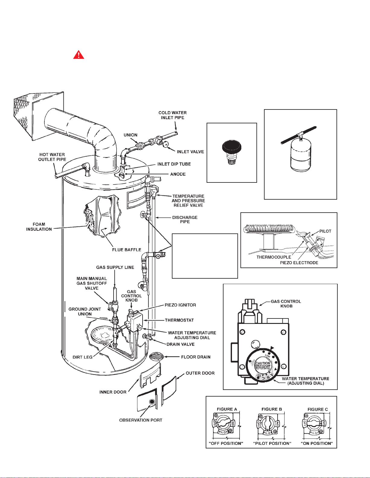
GET TO KNOW YOUR WATER HEATER
TYPICAL INST ALLATION
WARNING
DO NOT A TTEMPT TO OPERA TE W A TER HEATER WITH COLD
WA TER INLET VAL VE CLOSED.
REPLACEMENT P ARTS
Replacement parts may be ordered through authorized
servicers or distributors. Refer to the Yellow Pages for where to
call or contact A. O. Smith Water Products Company, 500
Tennessee Waltz Parkway, Ashland City, TN 37015,
1-800-433-2545. When ordering parts, provide complete
model and serial numbers (see rating plate), quantity and
name of part desired (as listed in Figure 1). Standard
hardware items may be purchased locally.
THERMAL
EXPANSION T ANK
V ACUUM RELIEF
VALVE
INSTALL PER LOCAL
CODES.
INSTALL THERMAL EXP ANSION
TANK IF WATER HEATER IS
INSTALLED IN A CLOSED
SYSTEM.
(DO NOT CAP OR PLUG)
CERTAIN MODELS ARE
EQUIPPED WITH SIDE
PLUMBING CONNECTIONS
FOR SPACE HEA TING. THE
HOT AND COLD FITTING
ASSEMBLIES (PART #900126-2)
CAN BE ORDERED THROUGH
THE MANUFACTURER.
GAS PILOT & MAIN BURNER
THERMOST AT
ALL PIPING MATERIALS TO BE
SUPPLIED BY CUSTOMER.
GAS CONTROL
FIGURE 1
2
GENERAL SAFETY
INFORMATION
EXTERNAL DAMAGE
Do not operate the water heater until it has been fully checked out
by a qualified technician, if the water heater:
• Has been exposed to fire or damage.
• Displays evidence of sooting.
• Produces steam or unusually hot water.
combustion, resulting in fire, asphyxiation, serious personal
injury or death.
•
Do not cover the outer door, thermostat or temperature &
pressure relief valve.
•
Do not cover the instruction manual. Keep it on the side of the
water heater or nearby for future reference.
•
Do obtain new warning and instruction labels from A.O. Smith
for placement on the blanket directly over the existing labels.
INST ALLATION
If the water heater has been flooded it must be replaced.
CHEMICAL V APOR CORROSION
WARNING
CORROSION OF THE FLUEWAYS AND VENT SYSTEM MAY
OCCUR IF AIR FOR COMBUSTION CONTAINS CERTAIN
CHEMICAL VAPORS. SUCH CORROSION MAY RESULT IN
FAILURE AND RISK OF ASPHYXIA TION.
Spray can propellants, cleaning solvents, refrigerator and air
conditioning refrigerants, swimming pool chemicals, calcium
and sodium chloride (water softener salt), waxes and process
chemicals are typical compounds which are potentially corrosive.
Do not store products of this sort near the heater. Also, air which is
brought in contact with the heater should not contain any of these
chemicals. If necessary, uncontaminated air should be obtained
from remote or outside sources. The limited warranty is voided
when failure of water heater is due to a corrosive atmosphere.
(Refer to the limited warranty for complete terms and conditions).
EXTENDED NON-USE PERIODS
WARNING
HYDROGEN GAS CAN BE PRODUCED IN A HOT WATER
SYSTEM SERVED BY THIS HEA TER THA T HAS NOT BEEN USED
FOR A LONG PERIOD OF TIME (GENERALLY TWO WEEKS OR
MORE).
reduce the risk of injury under these conditions, it is
recommended that the hot water faucet be opened for several
minutes at the kitchen sink before using any electrical appliance
connected to the hot water system. If hydrogen is present, there
will probably be an unusual sound such as air escaping through
the pipe as the water begins to flow.
SMOKING OR OPEN FLAME NEAR THE F AUCET A T THE TIME IT
IS OPEN.
HYDROGEN GAS IS EXTREMELY FLAMMABLE. To
THERE SHOULD BE NO
INSULA TION BLANKETS
Insulation blankets available to the general public for external use
on gas water heaters are not necessary with A. O. Smith product s.
The purpose of an insulation blanket is to reduce the standby
heat loss encountered with storage tank water heaters. Your
A. O. Smith water heater meets or exceeds the National Appliance
Energy Conservation Act standards with respect to insulation and
standby loss requirements, making an insulation blanket
unnecessary.
WARNING
Should you choose to apply an insulation blanket to this heater,
you should follow these instructions (See Figure 1 for
identification of components mentioned below). Failure to follow
these instructions can restrict the air flow required for proper
REQUIRED ABILITY
INSTALLATION OR SERVICE OF THIS WATER HEATER
REQUIRES ABILITY EQUIVALENT TO THAT OF A LICENSED
TRADESMAN IN THE FIELD INVOLVED. PLUMBING, AIR
SUPPL Y, VENTING AND GAS SUPPLY ARE REQUIRED.
INSPECT SHIPMENT
There may be hidden damage caused in transit. Check to be
certain all parts of the venting system, as listed below, are present.
CAUTION!!! IF THERE ARE ANY DAMAGED PARTS, DO NOT
INSTALL THIS W A TER HEA TER. REPORT ANY SHORT AGE TO
YOUR DISTRIBUTOR OR DAMAGE TO YOUR CARRIER.
VENT KIT ASSEMBL Y COMPONENTS
1 3” 90° elbow 1 Finishing collar (inside)
1 6” 90° elbow 1 Finishing collar (outside)
1 3” tube 1 Terminal Vent Cap Assembly
1 6” tube 1 Tube silicone sealant
GENERAL
The installation must conform to these instructions and the local
code authority having jurisdiction. In the absence of local codes,
the installation must comply with the current editions of the
National Fuel Gas Code, ANSI Z223.1/NFPA 54. The code is
available from the Canadian Standards Association, 8501 East
Pleasant Valley Road, Cleveland, OH 44131.
FACTS T O CONSIDER ABOUT THE LOCA TION
You should carefully choose an indoor location for the new water
heater, because the placement is a very important consideration
for the safety of the occupants in the building and for the most
economical use of the appliance. This water heater is not for use
in manufactured (mobile) homes or outdoor installation.
Whether replacing an old water heater or putting the water heater
in a new location, the following critical points must be observed.
When installing the heater, consideration must be given to proper
location. The water heater should be located as close to or
centralized to the water piping system as possible. The water
heater should be located in an area not subject to freezing
temperatures.
THE HEATER SHOULD BE LOCATED IN AN AREA WHERE
LEAKAGE OF THE T ANK OR CONNECTIONS WILL NOT RESUL T IN
DAMAGE TO THE AREA ADJACENT TO THE HEA TER OR TO LOWER
FLOORS OF THE STRUCTURE. When such locations cannot be
avoided, a suitable drain pan should be installed under the heater.
Such pans should have a minimum length and width of at least 2
3
inches greater than the diameter of the heater and should be piped to
an adequate drain. Drain pans suitable for these heaters are
available from your dealer or A. O. Smith Water Products Company,
500 Tennessee Waltz Parkway, Ashland City, TN 37055. Contact us at
our website: www.aosmithwaterheaters.com,phone: 800.433.2545,
or fax: 1.800.433.2515.
Water heater life depends upon water quality, water pressure
and the environment in which the water heater is installed.
Water heaters are sometimes installed in locations where
leakage may result in property damage, even with the use of a
drain pan piped to a drain. However, unanticipated damage
can be reduced or prevented by a leak detector or water shut-off
device used in conjunction with a piped drain pan. These
devices are available from some plumbing supply
wholesalers and retailers, and detect and react to leakage in
various ways:
• Sensors mounted in the drain pan that trigger an alarm or
turn off the incoming water to the water heater when leakage
is detected.
• Sensors mounted in the drain pan that turn off the water
supply to the entire home when water is detected in the
drain pan.
• Water supply shut-off devices that activate based on the
water pressure differential between the cold water and hot
water pipes connected to the water heater.
WARNING
DO NOT INSTALL THIS WATER HEATER DIRECTLY ON A
CARPETED FLOOR. A FIRE HAZARD MA Y RESUL T.
Instead the
water heater must be placed on a metal or wood panel extending
beyond the full width and depth by at least 3 inches (76.2mm) in
any direction. If the heater is installed in a carpeted alcove or
closet, the entire floor shall be covered by the panel.
Refer to Figure 1 for typical installation. A suitable pipe thread
sealant must be used to prevent leakage.
WA TER (POT ABLE) HEA TING AND SP ACE HEA TING
1. All piping components connected to this unit for space heating
applications shall be suitable for use with potable water.
2. Toxic chemicals, such as those used for boiler treatment, shall
NEVER be introduced into this system.
3. This unit may NEVER be connected to any existing heating
system or component(s) previously used with a non-potable
water heating appliance.
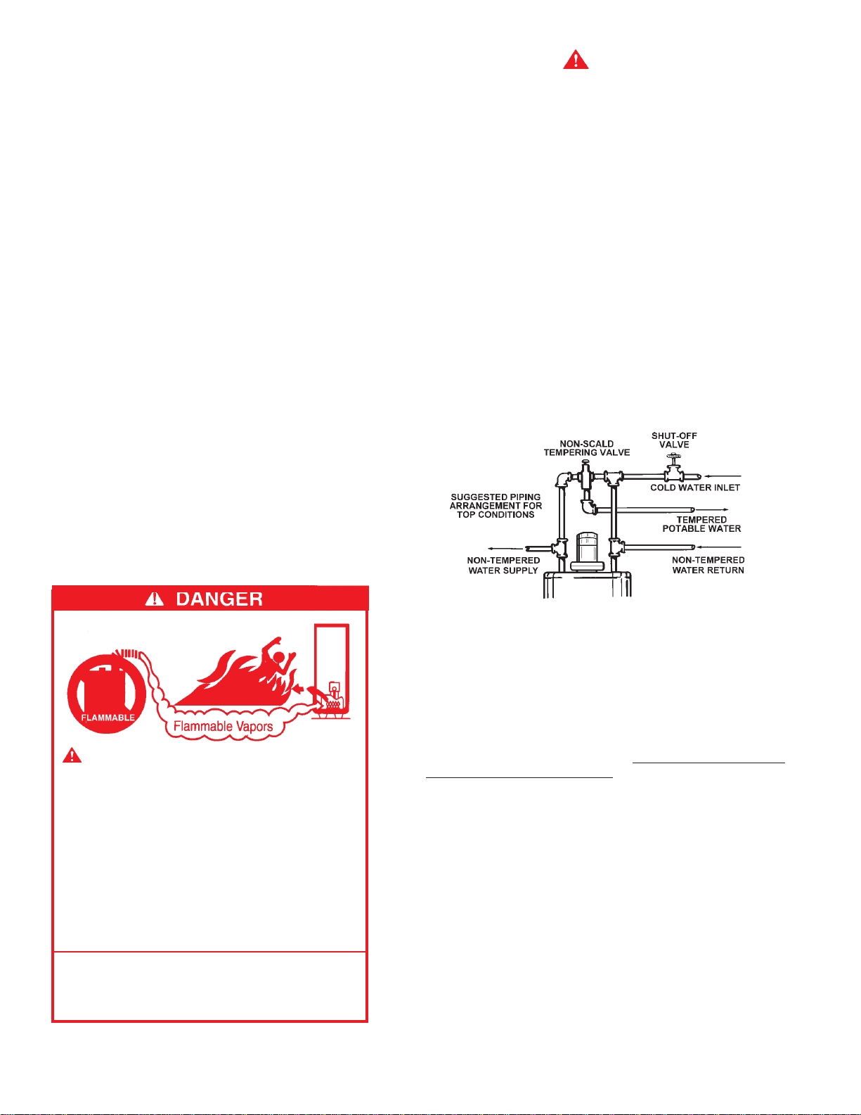
4. When the system requires water for space heating at
temperatures higher than required for domestic water
purposes, a tempering valve must be installed, see Figure 2
for suggested piping arrangement.
• Devices that will turn off the gas supply to a gas water heater
while at the same time shutting off its water supply.
Under no circumstances is the manufacturer to be held liable for
any water damage in connection with this water heater.
Vapors from flammable
liquids may explode and catch
fire causing death or severe
burns.
Do not use or store flammable
products such as gasoline,
solvents or adhesives in the same
room or area near the water heater.
Keep flammable products:
1. far away from heater,
2. in approved containers,
3. tightly closed and
4. out of children’s reach.
Installation:
Do not install water heater where
flammable products will be stored
or used unless the main burner
and pilot flames are at least 18”
Water heater has a main burner
and pilot flame. The pilot flame:
1. is on all the time and
2. will ignite flammable vapors.
Vapors:
1. cannot be seen,
2. are heavier than air,
3. go a long way on the floor
and
4. can be carried from other
rooms to the pilot flame by
air currents.
above the floor. This will
reduce, but not eliminate the
risk of vapors being ignited by
the main burner or pilot flame.
The location selection must provide adequate clearances for
servicing and proper operation of the water heater.
FIGURE 2
CLOSED WATER SYSTEM
A closed system will exist if a back-flow preventer (check valve),
pressure reducing valve, or other similar device is installed in the
cold water line between the water heater and the street main (or
well). Excessive pressure may develop due to the thermal
expansion of heated water causing premature tank failure or
intermittent relief valve operation.
This type of failure is not
covered by the limited warranty. An expansion tank may be
necessary in the cold water supply to alleviate this situation, see
Figure 1. Contact the local plumbing authority.
If the temperature and pressure relief valve on the appliance
discharges periodically, this may be due to thermal expansion in a
closed water supply system. Contact the water supplier or local
plumbing inspector on how to correct this situation.
DO NOT
PLUG THE TEMPERA TURE AND PRESSURE RELIEF V AL VE.
GAS CONNECTIONS
The minimum gas supply pressure for input adjustment is 5.0”
W.C. (1.2 kPa) for natural gas and 11.0” W.C. for propane gas.
THE HEATER IS NOT INTENDED FOR OPERA TION AT HIGHER
THAN 10.5” WATER COLUMN (2.6 kPa) SUPPLY PRESSURE.
EXPOSURE TO HIGHER GAS SUPPL Y PRESSURE MA Y CAUSE
DAMAGE TO THE CONTROL WHICH COULD RESULT IN FIRE
OR EXPLOSION.
improper testing of gas lines or emergency malfunction of the
supply system, the control must be checked for safe operation.
4
If over-pressure has occurred such as through
Make sure that the outside vents on the supply regulators and the
safety vent valves are protected against blockage. These are
parts of the gas supply system not the heater. Vent blockage may
occur during ice storms.
IT IS IMPORTANT TO GUARD AGAINST CONTROL FOULING
FROM CONTAMINANTS IN THE GAS WAYS. SUCH FOULING
MAY CAUSE IMPROPER OPERA TION, FIRE OR EXPLOSION.
All piping must comply with local codes and ordinances or with
the current edition of National Fuel Gas Code (ANSI Z223.1/
NFPA-54) whichever applies.
REFER TO FIGURE 1 FOR CONNECTION DETAILS. BEFORE
ATTACHING THE GAS LINE BE SURE THAT ALL GAS PIPE IS
CLEAN ON THE INSIDE.
TO TRAP ANY DIRT OR FOREIGN MATERIAL IN THE GAS
SUPPLY LINE, A DIRT LEG (SOMETIMES CALLED DRIP LEG)
MUST BE INCORPORA TED IN THE PIPING, FIGURE 1. The dirt
leg must be readily accessible. Install in accordance with
recommendations of serving gas supplier. Refer to the latest
edition of the National Fuel Gas Code ANSI Z223.1.
To prevent damage, care must be taken not to apply too much
torque when attaching gas supply pipe to thermostat gas inlet.
The thermostat inlet has a pad for use with a backup wrench.
Apply joint compounds (pipe dope) sparingly and only to the male
threads of pipe joints. Do not apply compound to the first two
threads. Use compounds resistant to the action of liquefied
petroleum gases. Do not use teflon tape on thermostat fittings.
DISCONNECT THE APPLIANCE FROM THE GAS SUPPLY
PIPING SYSTEM DURING ANY SUPPLY PRESSURE TESTING
EXCEEDING 1/2 PSI (3.5 kPa). GAS SUPPLY LINE MUST BE
CAPPED WHEN DISCONNECTED FROM THE HEATER. FOR
TEST PRESSURES AT 1/2 PSI (3.5 kPa) OR LESS, THE
APPLIANCE NEED NOT BE DISCONNECTED, BUT MUST BE
ISOLATED FROM THE SUPPLY PRESSURE TEST BY CLOSING
THE MAIN MANUAL GAS V AL VE.
not exceed the working pressure shown on the rating plate of the
heater. In addition, the hourly BTU rated temperature steam
discharge capacity of the relief valve shall not be less than the
input rating of the heater.
THE RELIEF VALVE AND TANK. DO NOT PLUG THE RELIEF
VALVE.
The drain line connected to this valve must not contain a reducing
coupling or other restriction and must terminate near a suitable
drain to prevent water damage during valve operation. The
discharge line shall be installed in a manner to allow complete
drainage of both the valve and line. DO NOT THREAD, PLUG OR
CAP THE END OF THE DRAIN LINE.
NO VAL VE IS TO BE PLACED BETWEEN
VENTING
WARNING
NEVER OPERATE THE HEATER UNLESS IT IS VENTED TO THE
OUTDOORS AND HAS ADEQUATE AIR SUPPLY TO AVOID
RISKS OF IMPROPER OPERATION, FIRE, EXPLOSION OR
ASPHYXIATION.
DO NOT OBSTRUCT THE FLOW OF COMBUSTION AND
VENTILATING AIR. ADEQUATE AIR FOR COMBUSTION AND
VENTILA TION MUST BE PROVIDED FOR SAFE OPERA TION.
VENT PIPE TERMINA TION
Before installing water heater determine placement of vent pipe
termination.
MAKE CERTAIN TO OBSERVE VENT LOCATION LIMITATION,
SEE FIGURES 4 & 5.
CAUTION
Use only the vent kit assembly supplied with this water heater or if
needed one of the three listed optional flue extensions. See
Figure 10 for possible combinations. VENTING OR
TERMINATION WITH ANY OTHER KIT NOT LISTED IS NOT
RECOMMENDED AND COULD AFFECT THE SYSTEMS
PERFORMANCE AND RESULT IN A SAFETY HAZARD.
BEFORE PLACING THE HEATER IN OPERATION, CHECK
FOR GAS LEAKAGE. USE SOAP AND WATER SOLUTION OR
OTHER MATERIAL ACCEPTABLE FOR THIS PURPOSE. DO
NOT USE MATCHES, CANDLES, FLAME OR OTHER
SOURCES OF IGNITION TO LOCA TE GAS LEAKS.
RELIEF V AL VE
A NEW TEMPERATURE AND PRESSURE RELIEF VALVE
COMPL YING WITH THE ST ANDARD FOR RELIEF VALVES AND
AUTOMATIC GAS SHUT OFF DEVICES FOR HOT WATER
SUPPL Y SYSTEMS, ANSI Z21.22 (CURRENT EDITION) MUST
BE INSTALLED IN THE HEATER IN THE MARKED OPENING
PROVIDED, SEE FIGURE 1. THE V ALVE MUST BE OF A SIZE
(INPUT RATING) THA T WILL BE ADEQUATE FOR YOUR SIZE
HEATER.
Check the metal tag on the relief valve and compare it to the
heater’s rating plate. The pressure rating of the relief valve must
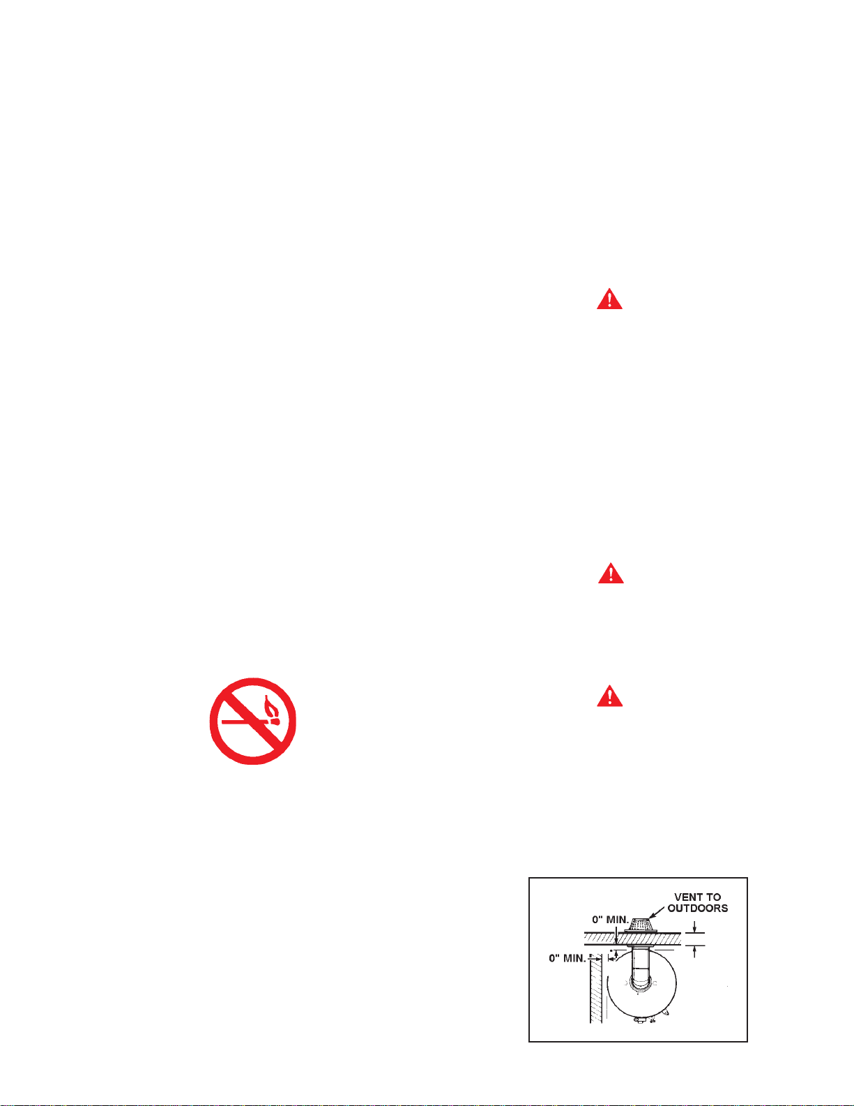
WARNING
MINIMUM CLEARANCES BETWEEN THE WATER HEATER AND
COMBUSTIBLE AND NONCOMBUSTIBLE CONSTRUCTION
ARE: 0 INCHES FROM SIDES, 0 INCHES FROM BACK, 4 INCHES
FROM FRONT OF JACKET TO CLOSET DOOR AND 3 INCHES
FROM TOP OF JACKET TO COMBUSTIBLE AND
NONCOMBUSTIBLE MATERIAL. MINIMUM VENT CLEARANCE: 0
INCHES. PROVIDE 24 INCHES FRONT CLEARANCE FOR
SERVICING AND ADEQUATE CLEARANCE BETWEEN THE
JACKET TO P & CEILING FOR SERVICING THE FLUE AREA , SEE
FIGURES 3 AND 3A.
FIGURE 3
5
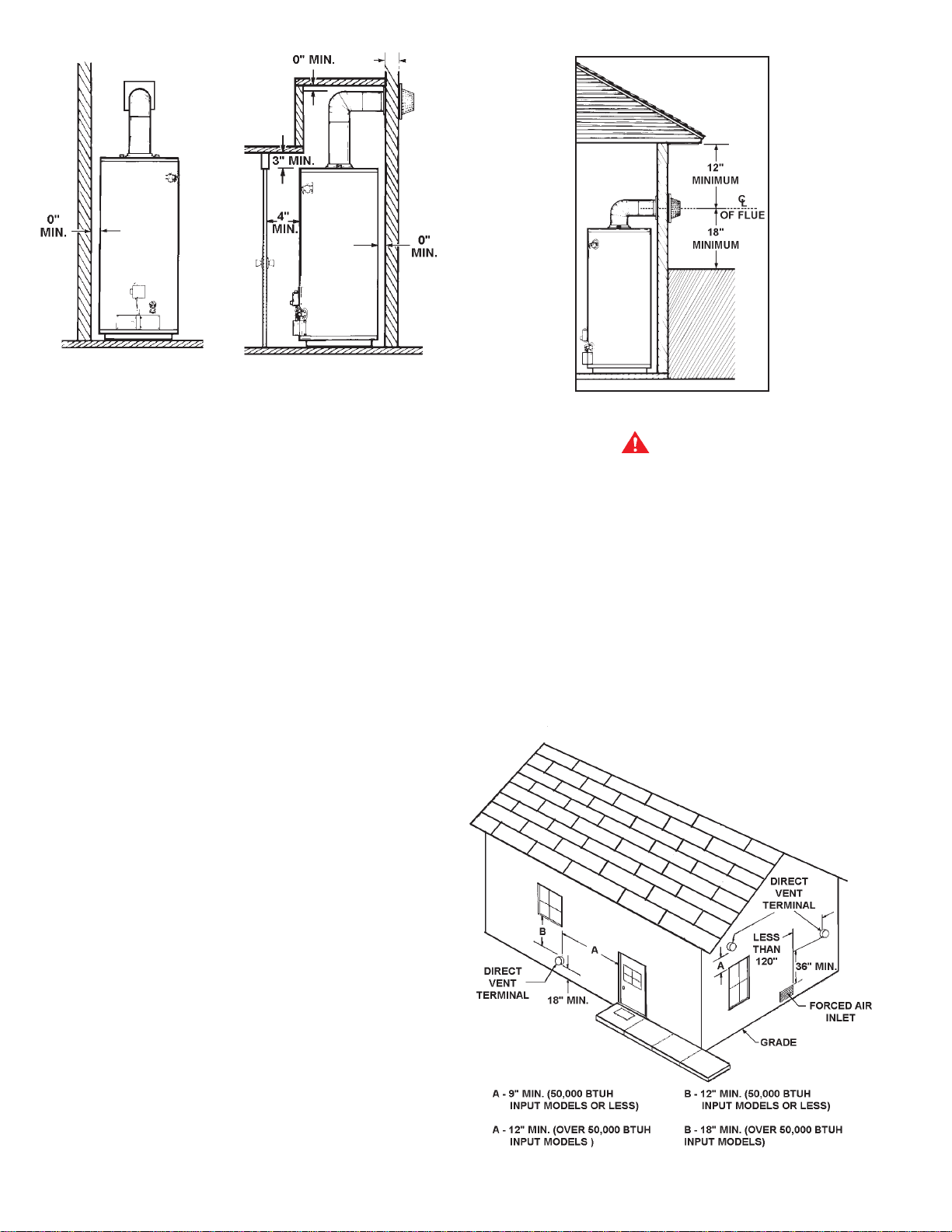
FIGURE 3A
COMBUSTION AIR AND VENTILA TION
When determining the installation location for a direct vent
water heater, snow accumulation and drifting should be
considered in areas where applicable.
VENTING CLEARANCES
• 18” minimum in all directions from any obstruction that may
interfere.
• 18” minimum from the ground and 12” from ceiling
overhangs, see Figure 4.
• The direct vent terminal shall terminate at least 3 feet above
any forced air inlet located within 10 feet, see Figure 5.
• 9” minimum horizontally from or above any door, window or
gravity air inlet into the building (50,000 BtuH input or less.)
FIGURE 4
WARNING
Vent termination must not be within 4 feet of any items such as
gas meters, gas valves or other gas regulating equipment.
OPTIONAL WIRE GRILL
When the water heater vent cap is low enough to be touched
accidentally, or is accessible to small children, installation of a
protective vent cover is recommended. Some local codes may
require a vent cap cover. Figure 9 shows the optional wire vent
cap protector available from the water heater manufacturer.
A wire mesh chain link fence (as shown in Figure 9) may be
used instead of the factory cover. Care should be taken to
maintain adequate ventilation around the vent cap. If a chain
link fence is installed, it must not be used as a storage area for
items that may block proper ventilation.
• 12” minimum horizontally from or above any door, window or
gravity air inlet into the building (over 50,000 BtuH input).
• 12” minimum below any door, window or gravity air inlet into
the building (50,000 BtuH input or less).
• 18” minimum below any door, window or gravity air inlet into
the building (over 50,000 BtuH input).
• 18” minimum from other gravity or natural appliance outlet
vents when directly above or 135° to either side of center
line, see Figure 6.
• 36” minimum from any outlet vents when directly below or
45° to either side of center line, see Figure 7.
• 36” minimum in all directions from any other forced air
appliance outlet vent, see Figure 7.
• The location selection must provide clearances for
servicing and proper operation of the water heater, see
Figure 8.
• Vent termination must not be within 4 feet of any items such
as gas meters, gas valves or other gas regulating
equipment.
FIGURE 5
6
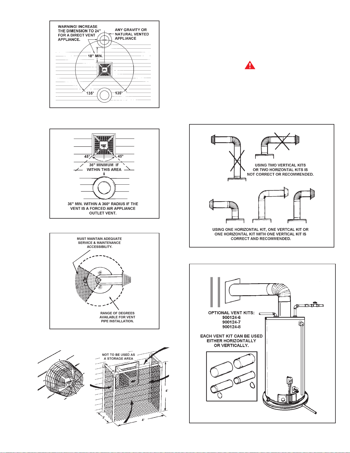
FLUE EXTENSIONS
There are three optional extension kits available. Any
combination of the three kits can be chosen; however, only one
kit can be used vertically and/or horizontally, see Figures 10
and 11.
WARNING
At no time can more than one Vertical and/or one Horizontal
Vent Kit be used.
Unless otherwise specified at the time of ordering, a standard
extension kit is individually packaged and shipped within the
water heater carton.
FIGURE 6
FIGURE 7
POSSIBLE EXTENSION COMBINA TIONS
FIGURE 10
FIGURE 8
FIGURE 9
FIGURE 11
7
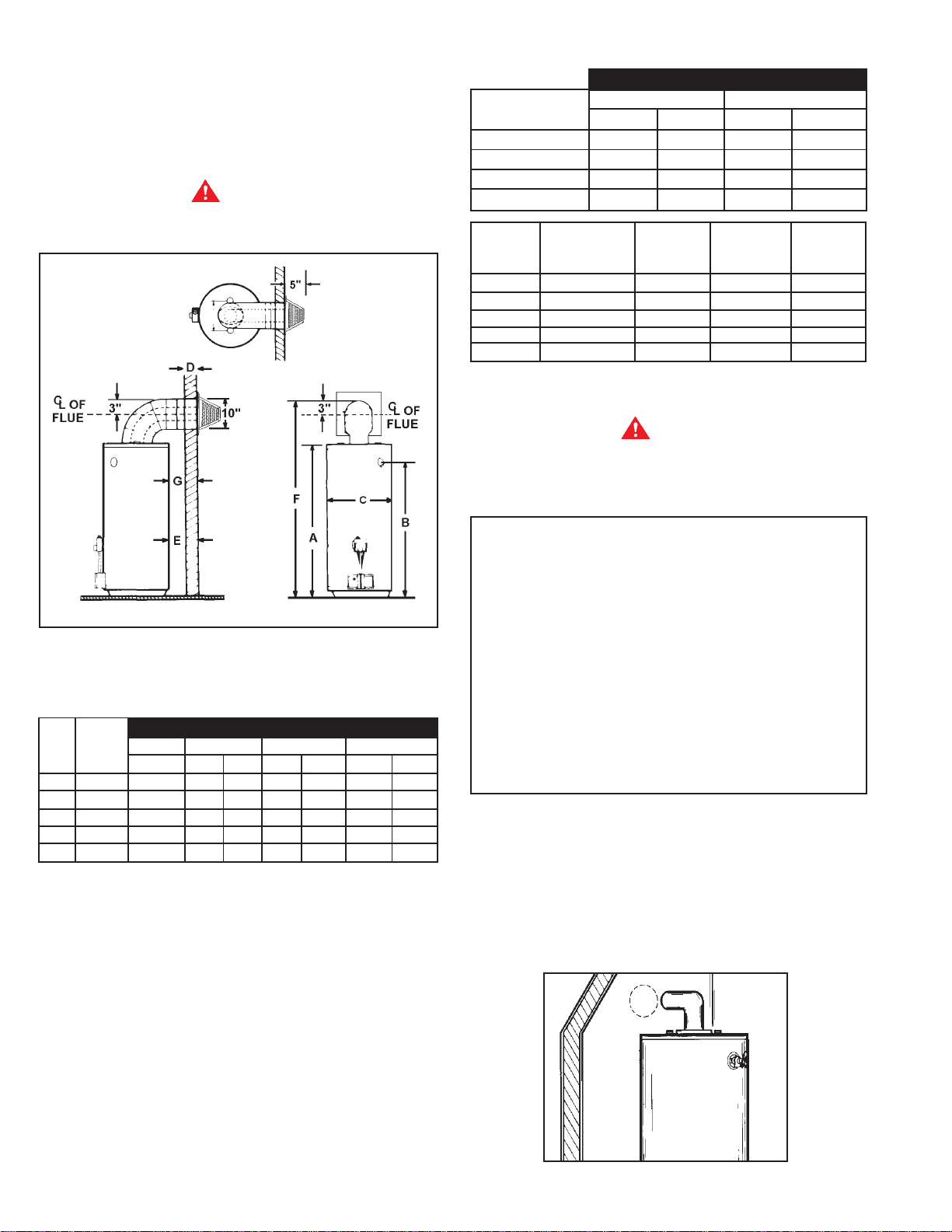
VERTICAL (EXTENSION KIT) HEIGHT
It is simple to determine which kit is needed for vertical height.
Take the total height (to the top of the flue) required and
comparing that to “F DIMENSION” in TABLE 1, it can be
determined which kit needs to be used vertically.
WARNING
Obstructions and deteriorated vent systems may present
serious health risk or asphyxiation.
T ABLE 2.
E DIMENSIONS
40-50 Gal. 75 Gal.
VENT KITS MIN. MAX. MIN. MAX.
900068-7-STD. 3-1/2 10 7/8 7-3/8
900124-6 10 15-1/2 7-3/8 12-7/8
900124-7 15-1/2 26-1/2 12-7/8 23-7/8
900124-8 26-1/2 48 23-7/8 45-3/8
*BTU’S in
*GAL. 1000’s
CAP. NAT/L.P. A B C
40 36/36 48-3/4 41-3/4 21
50 38/38 57-1/2 50-1/2 21
40 40/40 48-3/4 41-3/4 21
50 48/44 61 54 21
75 55 NA T. 63 54-3/4 26-1/4
*See models and rating plate attached to the water heater for
specific model number and other detailed information.
WARNING
Be sure vent pipe is properly connected to prevent escape of
dangerous flue gases which could cause deadly asphyxiation.
ALL INST ALLA TIONS
FIGURE 12
T ABLE 1.
BTU’s F DIMENSION
*GAL. in 1000’s900068-7 900124-6 900124-7 900124-8
CAP . NAT/L.P. STD. MIN. MAX. MIN. MAX. MIN. MAX.
40 36/36 63-3/4 72 77 77 88 88 110
50 38/38 72 80-3/4 86 86-1/4 97-1/4 97-1/4 118-3/4
40 40/40 63-3/4 72 77 77 88 88 110
50 48/44 76 84-1/4 89-3/4 89-3/4 100-3/4 100-3/4 122-3/4
75 55 NAT. 76-1/4 84-1/2 89-1/2 89-1/2 100-1/2 100-1/2 122-1/2
* See models and rating plate attached to the water heater for
specific model number and other detailed information.
HORIZONTAL (EXTENSION KIT)
To determine the horizontal length and extension kit needed,
simply plug the dimensions “D” and “G” into the equation
below. The answer “E” should then be located in TABLE 2. The
size range in which “E” dimension falls indicates the kit that
should be used horizontally to obtain the desired length.
For ease of assembly the installation of the various kit
combinations has been broken into individual sections.
The two steps below are common to all installations. Once
these have been performed, you need only to refer to the
type installation that pertains to you.
Installation Using V ent Kits:
1. Standard V ent Kit..................................... Page 8
2. Optional Vertical V ent Kit ....................... Page 10
with Standard V ent Kit
3. Optional Horizontal Vent Kit ................... Page 13
4. Optional Horizontal and .......................... Page 15
Vertical Vent Kits
CUTTING THE OPENING THROUGH
THE OUTSIDE WALL
After thoroughly reading the “Locating the New Water Heater”
section of this manual and you have chosen a suitable water
heater installation site, use the chart below to determine
dimensions for the opening in the wall.
Cut a 6
1
/4” diameter hole completely through the outside wall.
EQUATION: D + G = E
“D” = The wall thickness
“G” = The distance wanted between the edge of the water
heater and the inside edge of the wall
“E” = The distance the extension kit must be able to extend
FIGURE 13
8
WATER HEATER ATTITUDE
There is a certain amount of variation permissible with regard
to the direction the water heater faces.
Standing in front of the water heater (gas control facing you), set
the 3” diameter elbow (slotted end) on the flue. This will give
you a better understanding of the relation of the vent assembly
to the opening in the wall and more importantly any possibly of
interference of venting and water piping.
The direction of the water heater can now be made. Also
consider the gas control valve to insure installation, lighting,
and maintenance accessibility are retained.
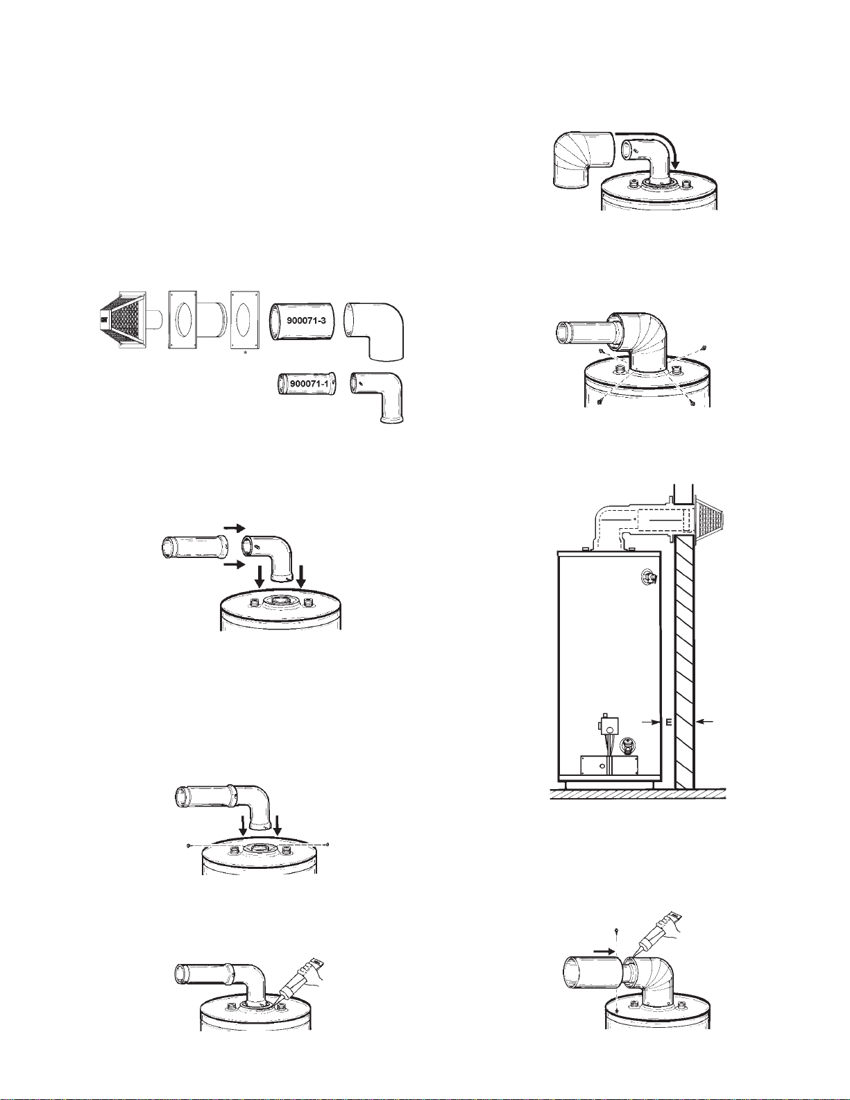
STANDARD VENT KIT INSTALLATION #1
4. First remove the 3” horizontal extension from the elbow.
Starting with the long end (with four securing holes), place
the 6” diameter vent elbow over the 3” diameter elbow.
Bend the round end “oval” to fit the flared oval end of the
jacket top.
FIGURE 18
5. Making sure the 6” diameter elbow is centered around the
3” diameter flue, secure the 6” diameter vent pipe using
four sheet metal screws at the connection of the jacket top.
* Each part is stamped with a
part number.
FIGURE 14
The opening through the wall should be cut at this time. If it
hasn’t been, refer back to that section.
1. Lock the elbow to the straight 3” flue pipe. Set this assembly
in place on the end of the water heater’sflue collar.
FIGURE 15
2. Mark the flue collar at the slots in the elbow. Using a #22 drill
bit, drill holes into the flue collar at the two
slots and secure the elbow to the flue collar using the
screws provided.
NOTE: Make sure elbow is properly aligned to opening in
the outside wall.
FIGURE 19
V
6. The standard vent kit includes a 6” diameter extension pipe
which is used when “E” dimension is over 6 1/2”.
FIGURE 16
3. Using the tube of sealant supplied, run an ample amount
around the oval flare of the jacket.
FIGURE 17
FIGURE 20
7. If “E” is less than 6 1/2” move to next step.
If “E” dimension is over 6 1/2”, assemble the 6” diameter
extension pipe (crimped end) to the 6” diameter vent elbow
and secure using two sheet metal screws.
FIGURE 21
9
 Loading...