

A.O. Smith GDV-40, GDV-50, GDVT-50, GDV-75 DATASHEET
Residential Gas Water Heaters
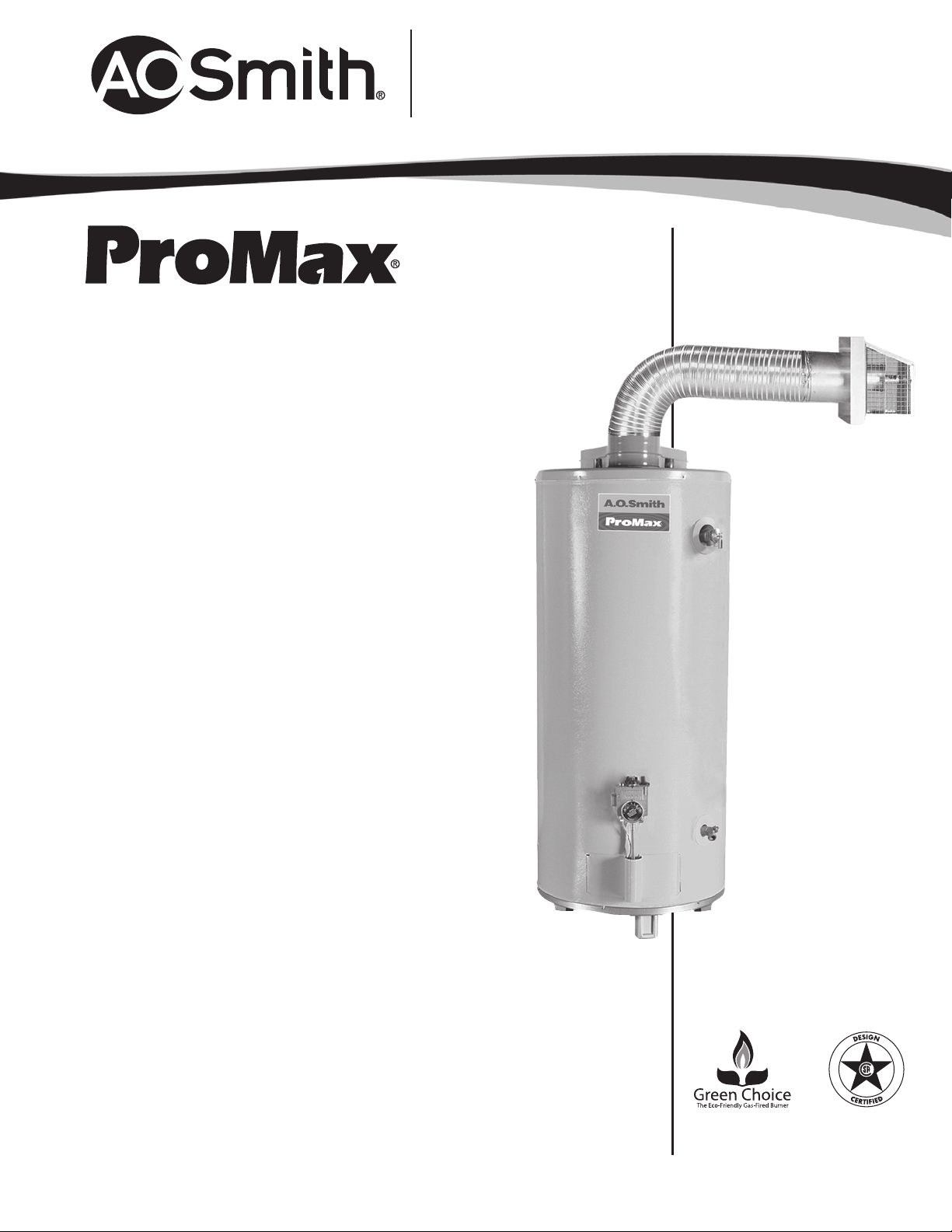
DIRECT-VENT
Features
DIRECT-VENT DESIGN
One-pipe, dual-channel closed system draws all make-up air from outside
the home, eliminating problems caused by insufficient indoor
ventilation and is FVIR compliant.
Horizontal air intake and venting on all models up to 80 inches from
outside wall with no electrical power needed.
DYNACLEAN™ DIFFUSER DIP TUBE
Helps reduce lime and sediment buildup, maximizes hot water output.
Made from long-lasting PEX cross-linked polymer.
GREEN CHOICE® GAS BURNER
Patented “Eco-Friendly” design reduces NOx emissions up to 33% and
complies with requirements for less than 40ng/j for low NOx.
PUSH BUTTON PIEZO IGNITOR
Makes lighting pilot fast and easy with one hand push button spark
ignition.
HEAT TRAP NIPPLES
Factory-installed.
DURABLE TAMPER-RESISTANT BRASS DRAIN VALVE
PERMAGLAS®GLASS COATING
Protects steel tank from buildup.
CSA CERTIFIED AND ASME RATED T&P
RELIEF VALVE
6-YEAR LIMITED TANK & PARTS WARRANTY
For complete information, consult written warranty or A. O. Smith Water
Products Company.
CODE COMPLIANCE
UBC, CEC, SBCC, HUD and BOCA National Codes. Meets or exceeds
the thermal efficiency and standby loss requirements of the U.S.
Department of Energy and current edition of ASHRAE/IESNA 90.1.
Meets or exceeds the Federal Energy Efficiency Standards effective
January 20, 2004, according to the National Appliance Energy
Conservation Act (NAECA) of 1992.
DESIGN-CERTIFIED BY CSA INTERNATIONAL
According to ANSI Z21.10.1– CSA 4.1 Standards governing storage-type water
heaters.
September 2010R
®
Page 1 of 2
AOSRG45700

Residential Gas Water Heaters
DIRECT-VENT
MODEL
NUMBER
FIRST
HOUR
RATING
GALLONS
ENERGY
FACTOR
GAL.
CAP.
BTU
INPUT
PER HOUR
RECOVERY
90ºF RISE
GALLONS
PER HOUR
DIMENSIONS IN INCHES
A B C** D E F
VENT
OUTLET*
APPROX.
SHIPPING
WEIGHT
(LBS)
GDV-40 73 .62 40 38,000 41 68 54-3/4 22-1/4 16 12-1/4 45-1/4 Co-Axial 167
GDV-50 87 .60 50 42,000 45 76 63-3/4 22-1/4 16 12-1/4 54 Co-Axial 185
GDVT-50 88 .59 50 50,000 55 76 64-3/4 22-1/4 16-1/4 12-1/2 55-1/2 Co-Axial 187
GDV-75 131 .59 75 55,000 60 76 65-3/4 26-1/4 16-1/4 12-1/2 55-1/2 Co-Axial 310
Recovery capacities based on actual performance tests.
* Dual-channel system has 3˝ vent pipe inside 6˝ air intake pipe, for the 40 & 50–gallon models.
The 75 gallon model uses a 4” x 7” co-axial pipe.
All Models Have 2” Foam Cavity.
Water connection 3/4” male all models.
75 gallon water connections are 12” on center.
** Allow 25 1/4¨ for 40 and 50–gallon models and 29 1/2¨ for 75–gallon models for
front–to–back dimensions for air intake at the rear of the heater.
GDV–40 Models are ENERGY STAR
®
qualified.
Important! Vent Installation and Termination Requirements
Maximum horizontal vent distance is 80” to outside of exterior wall.
Minimum horizontal vent distance is 17” to outside of exterior wall.
Vent pipes may be trimmed (cut) for short vent installations.
For vent installation less than 30” the vent restrictor is required.
Place restrictor over the flue outlet on heater before installing the outlet vent
pipe to the heater.
Recommended installation height for the heater vent pipe should be
68” for 40 gallon models and 76” for the 50-gallon and 75-gallon
models (vent height).
Offset Vent Arrangement
1. When replacing an existing direct vent model,
the new vent pipe may drop from the minimum
vent height as much as 7 1/4” to exit through the
existing vent opening in the exterior wall.
2. Vent may have one horizontal 90 degree turn before
exiting through exterior wall (Do not combine both
offset vent arrangements in one installation) (See
examples in the installation manual)
High Rise Vent Arrangement
3. When vent termination is more than 80” above the
base of the heater. The horizontal vent run must be
a minimum of 22” from the center of the heater to
the outside exterior wall surface. (See example in the
installation manual)
Vent termination clearance hole through the exterior
wall should be approximately 7” diameter.
Snow accumulation and drifting should be considered
when locating the termination.
An optional wire grill vent cap protector is available
through the parts department. Part number 9006627005.
See the installation manual for complete installation
and venting requirements.
A
B
D
6” DIA. on 40 & 50 Gal. Models
7” DIA. on 75 Gal. Models
C
E
40 & 50 gal.
MIN VENT
17
MAX VENT
80
6 DIA.
F
25-1/4
25-1/4
75 gal.
29-1/2
KFG
T&P
42°
47°
EXTERIOR
WALL
DRA
IN
75 gal. vent
termination
cap is not
interchangeable
with vent cap
on 40 & 50 gal.
models
FRONT
For Technical Information and Automated Fax Service, call 800-527-1953. A.O. Smith Corporation reserves the right to make produ ct changes or improvements without prior notice.
September 2010R
www.hotwater.com
Page 2 of 2
AOSRG45700
 Loading...