

A.O. Smith ELECTRIC WATER HEATERS User Manual
MODELS DEN AND DEL
COMMERCIAL ELECTRIC WATER HEATERS
• Installation • Electrical • Wiring Diagrams • Replacement Parts
• Operation • Maintenance • Leakage Checkpoints • Limited W arranty
A DIVISION OF A. O. SMITH CORPORA TION
McBee, South Carolina, USA
www.hotwater.com
CAUTION
TEXT PRINTED OR OUTLINED IN RED CONT AINS INFORMA TION RELA TIVE TO YOUR SAFETY.
PLEASE READ THOROUGHLY BEFORE INST ALLING AND USING THIS APPLIANCE.
PLACE THESE INSTRUCTIONS ADJACENT TO HEATER AND NOTIFY OWNER TO KEEP FOR FUTURE REFERENCE.
Printed in U.S.A. 0106 PART NO. 195201-002
SUPERSEDES PART NO. 195201-001
1
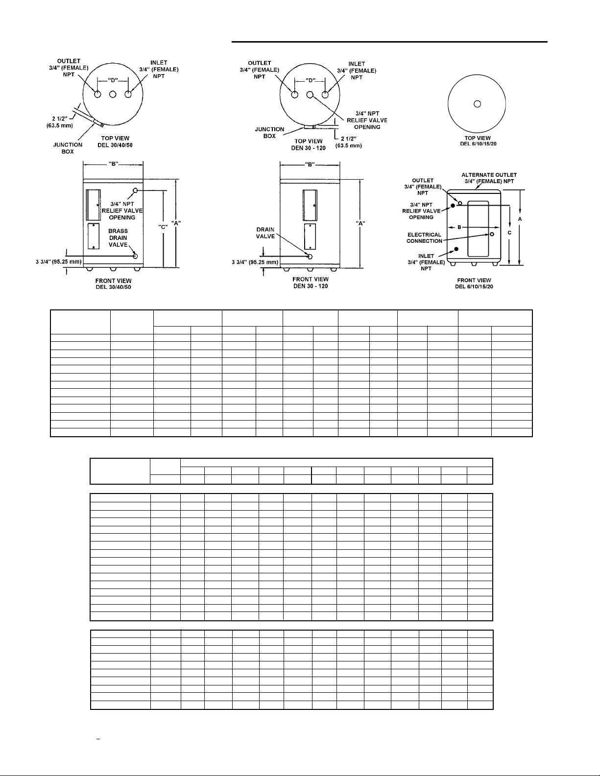
ROUGH-IN DIMENSIONS
ROUGH-IN DIMENSIONS
Models No. of Tank Capacity A B C D Shipping Weight.
Dimensions Elements US Gals. Litres inches mm inches mm inches mm inches mm Lbs. Kg.
DEL-6 1 6 23 15 1/2 394 14 1/4 362 11 279 - - 35 15.9
DEL-10 1 10 38 18 1/4 464 18 457 12 1/2 318 - - 54 24.5
DEL-15 1 15 57 26 660 18 457 20 1/2 521 - - 58 26.3
DEL-20 1 20 76 22 1/4 565 21 3/4 552 15 3/8 391 - - 73 33.1
DEL-30 2 30 114 30 7/8 784 21 3/4 552 24 1/8 613 8 203 100 45.4
DEL-40 2 40 151 32 1/4 819 24 610 25 9/16 649 8 203 12 5 56.7
DEL-50 2 50 189 32 1/4 819 26 1/2 673 25 1/8 638 8 203 166 75.3
DEN-30 2 30 114 34 1/2 876 20 1/2 521 - - 8 203 98 44.5
DEN-40 2 40 151 45 1/8 1146 20 1/2 521 - - 8 203 113 51.3
DEN-52 2 50 189 54 7/8 1394 20 1/2 521 - - 8 203 131 59.4
DEN-66 2 66 250 60 3/4 1543 21 3/4 552 - - 8 203 176 79.8
DEN-80 2 80 303 59 3/8 1508 24 610 - - 8 203 211 95.7
DEN-120 2 119 450 62 7/16 1586 29 3/8 746 - - 8 203 326 147.9
Approx.
RECOVERY CAP ACITIES
Element U.S. Gallons/Hr and Litres/Hr at TEMPERATURE RISE INDICATED
Wattage INPUT F° 36F° 40F° 54F° 60F° 72F° 80F° 90F° 100F° 108F° 120F° 126F°
(Upper/Lower) KW C° 20C° 22.2C° 30C° 33.3C° 40C° 44.4C° 50C° 55.5C° 60C° 66.6C° 70C°
NON-SIMULAT ANEOUS OPE RATION
/1500 GPH 17 15 11 10 8 8 7 6 6 5 5
/2000 GPH 23 20 15 14 11 10 9 8 8 7 6
/2500 GPH 28 25 19 17 14 13 11 10 9 8 8
3000/3000 GPH 34 30 23 20 17 15 14 12 11 10 10
4000/4000 GPH 45 41 30 27 23 20 18 16 15 14 13
4500/4500 GPH 51 46 34 30 25 23 20 18 17 15 14
5000/5000 GPH 56 51 38 34 28 25 23 20 19 17 16
6000/6000 GPH 68 61 45 41 34 30 27 24 23 20 19
SIMULAT ANEOUS OPERATION
3000/3000 GPH 68 61 45 41 34 30 27 24 23 20 19
4000/4000 GPH 90 81 60 54 45 41 36 32 30 27 26
4500/4500 GPH 101 91 68 61 51 46 41 36 34 30 29
5000/5000 GPH 113 101 75 68 56 51 45 41 38 34 32
6000/6000 GPH 135 122 90 81 68 61 54 49 45 41 39
1.5 LPH 64 58 43 38 32 29 26 23 21 19 18
2.0 LPH 85 77 57 51 43 38 34 31 28 26 24
2.5 LPH 107 96 71 64 53 48 43 38 36 32 30
3.0LPH1281158577645851 46433837
4.0 LPH 170 153 114 102 85 77 68 61 57 51 49
4.5 LPH 192 173 128 115 96 86 77 69 64 58 55
5.0 LPH 213 192 142 128 107 96 85 77 71 64 61
6.0 LPH 256 230 170 153 128 1 1 5 102 92 85 77 73
6 LPH 256 230 170 153 128 1 1 5 102 92 85 77 73
8 LPH 341 307 227 205 170 153 136 123 114 102 97
9 LPH 384 345 256 230 192 173 153 138 128 115 110
10 LPH 426 384 284 256 213 192 170 153 142 128 122
12 LPH 511 460 341 307 256 230 205 184 170 153 146
Recovery capacities at 100° F rise equal: for non-simultaneous element operation = 4.1 gal. x KW of one element; for simultaneous element operation
= 4.1 gal. x 2/3 KW of both elements. For other rises multiply element KW as previously explained by 410 and divide by temperature rise. Full load current for single
phase = total watts : voltage.
2
FOREWORD
Thank you for buying this energy efficient water heater from
State. We appreciate your confidence in our products. Detailed
installation diagrams are in this manual. These diagrams will
serve to provide the installer with a reference for the materials
and method of piping suggested. IT IS NECESSARY THAT ALL
WA TER PIPING AND THE ELECTRICAL WIRING BE INST ALLED
AND CONNECTED AS SHOWN IN THE DIAGRAMS.
In addition to these instructions, the water heater must be
installed in accordance with local codes and the authority having
jurisdiction.
GENERAL SAFETY INSTRUCTIONS
BE SURE TO TURN OFF POWER WHEN WORKING ON OR
NEAR THE ELECTRICAL SYSTEM OF THE HEATER. NEVER
TOUCH ELECTRICAL COMPONENTS WITH WET HANDS OR
WHEN STANDING IN WATER. WHEN REPLACING FUSES
AL WAYS USE THE CORRECT SIZE FOR THE CIRCUIT .
The principal components of the heater are identified on page 6.
The model and rating plate on page 5 interprets certain markings
into useful information. Both of these references should be
used to identify the heater, its components and optional
equipment.
reduce the risk of injury under these conditions, it is recommended
that the hot water faucet be opened for several minutes at a nearby
kitchen sink before using any electrical appliance connected to
the hot water system. If hydrogen is present, there will probably
be an unusual sound such as air escaping through the pipe as
the water begins to flow. THERE SHOULD BE NO SMOKING OR
OPEN FLAME NEAR THE F AUCET A T THE TIME IT IS OPENED.
CAUTION
AN ELECTRICAL GROUND IS REQUIRED TO REDUCE RISK
OF ELECTRIC SHOCK OR POSSIBLE ELECTROCUTION. THE
GROUND SCREW AT THE JUNCTION BOX IS FOR BONDING
THE HEATER TO A GROUNDED SERVICE ENTRANCE
CONDUCTOR, A GROUNDED SERVICE ENTRANCE RACEW A Y ,
OR AN EAR TH GROUNDING ELECTRODE CONDUCTOR.
WARNING
FAILURE TO FOLLOW THESE INSTRUCTIONS CAN RESULT
IN SERIOUS PERSONAL INJURY OR DEATH.
REQUIRED ABILITY
INSTALLATION OR SERVICE OF THIS WATER HEATER
REQUIRES ABILITY EQUIVALENT TO THAT OF A LICENSED
TRADESMAN IN THE FIELD INVOLVED. PLUMBING AND
ELECTRICAL WORK ARE REQUIRED.
WARNING
FOR CALIFORNIA INST ALLA TION THIS W A TER HEA TER MUST
BE BRACED, ANCHORED, OR STRAPPED TO A VOID FALLING
OR MOVING DURING AN EAR THQUAKE. SEE INSTRUCTIONS
FOR CORRECT INSTALLATION AND PROCEDURES.
INSTRUCTIONS MAY BE OBTAINED FROM YOUR LOCAL
DEALER, WHOLESALER, PUBLIC UTILITIES OR CALIFORNIA ’S
OFFICE OF STA TE ARCHITECT , 400 P STREET, SACRAMENTO,
CALIFORNIA 95814.
INSULA TION BLANKETS
Insulation blankets available to the general public for external
use on electric water heaters are not approved for use on your
State water heater. The purpose of an insulation blanket is to
reduce the standby heat loss encountered with storage tank
water heaters. Your State water heater meets or exceeds the
National Appliance Energy Act standards with respect to
insulation and standby loss requirements, making an insulation
blanket unnecessary.
Should you choose to apply an insulation blanket to this heater,
you should follow these instructions (See page 5 for identification
of components mentioned below). Failure to follow these
instructions can result in fire, serious personal injury or death.
• Do not cover the temperature & pressure relief valve.
• Do not cover the instruction manual. Keep it on the side of
the water heater or nearby for future reference.
• Do obtain new labels from State Water Heaters for placement
on the blanket directly over the existing labels.
WARNING
EXTENDED NON-USE PERIODS
HYDROGEN GAS CAN BE PRODUCED IN A HOT WATER
SYSTEM SERVED BY THIS HEA TER THA T HAS NOT BEEN USED
FOR A LONG PERIOD OF TIME (GENERALL Y TWO WEEKS OR
MORE).
HYDROGEN GAS IS EXTREMELY FLAMMABLE. To
CAUTION
GENERAL
The installation must conform to these instructions, the local
code authority having jurisdiction, and the requirements of the
power company. In the absence of code requirements follow
the current edition of NFPA-70, The National Electrical Code
which may be ordered from: National Fire Protection Association,
1 Batterymarch Park, Quincy , MA 02269.
LOCA TION
The water heater should be located as close as possible to/or
centralized to the water piping system. The water heater should
be located in an area not subject to freezing temperatures.
The heater should be located in an area where leakage of the
tank or connections will not result in damage to the area adjacent
to the heater or to lower floors of the structure.
When such locations cannot be avoided, a suitable drain pan
should be installed under the heater.
Such pans should be at least two inches deep, have a minimum
length and width of at least two inches greater than the diameter
of the heater and should be piped to an adequate drain.
Drain pans suitable for these heaters are available from your
distributor or A.O. Smith Water Heater Parts Fulfillment, 125
Southeast Parkway, Franklin, TN 37068.
Water heater life depends upon water quality, water pressure
and the environment in which the water heater is installed. Water
heaters are sometimes installed in locations where leakage
may result in property damage, even with the use of a drain pan
piped to a drain. However, unanticipated damage can be reduced
or prevented by a leak detector or water shut-off device used in
conjunction with a piped drain pan. These devices are available
from some plumbing supply wholesalers and retailers, and
detect and react to leakage in various ways:
• Sensors mounted in the drain pan that trigger an alarm or
turn off the incoming water to the water heater when leakage
is detected.
3
• Sensors mounted in the drain pan that turn off the water supply
to the entire home when water is detected in the drain pan.
• Water supply shut-off devices that activate based on the water
pressure differential between the cold water and how water
pipes connected to the water heater.
• Devices that will turn off the gas supply to a gas water heater
while at the same time shutting off its water supply.
CLEARANCES
CALCULATING
AMPERAGE/OVERCURRENT PROTECTION
The heaters come from the factory in two configurations:
1. Two wire C-2 circuit for single element heater equipped with
a high limit control, single phase power input.
2. Four wire A-8 circuit for dual element heater equipped with
two high limit controls, single phase or three phase power
input.
A minimum clearance of 4” must be allowed for access to
replaceable parts such as thermostats, drain valve and relief valve.
Adequate clearance for servicing this appliance should be
considered before installation, such as changing the anodes, etc.
FLOOD WARNING
IF THE HEATER BECOMES IMMERSED IN WATER UP TO OR
ABOVE THE LEVEL OF THE BOTTOM OF THE ELEMENT
DOORS, THE HEATER SHOULD BE EXAMINED BY A
COMPETENT SERVICE PERSON BEFORE IT IS PLACED IN
OPERA TION.
CHEMICAL V APOR CORROSION
Water heater corrosion and component failure can be caused by
the heating and breakdown of airborne chemical vapors. Spray
can propellants, cleaning solvents, refrigerator and air
conditioning refrigerants, swimming pool chemicals, calcium
and sodium chloride, waxes, and process chemicals are typical
compounds which are potentially corrosive. These materials
are corrosive at very low concentration levels with little or no odor
to reveal their presence. Products of this sort should not be stored
near the heater.
ELECTRICAL (GENERAL)
Check the heater model and rating plate information against the
characteristics of the branch circuit electrical supply. DO NOT
CONNECT THE HEATER TO AN IMPROPER SOURCE OF
ELECTRICITY. Contact the heater supplier for conversion
information if necessary.
The heater with dual elements is factory wired for connection to
a three wire, three-phase delta branch circuit, non-simultaneous
operation. In addition a ground conductor is required.
Element connection is for non-simultaneous operation. This
means only one element at a time operates. The wiring diagram,
on page 5, shows the heater may be field converted to
simultaneous element operation by moving the red wire on
“J” terminal to L1. It is then possible for both elements to operate
at once as determined by the thermostats. Regardless of
element connection the heater operates in an “unbalanced”
fashion.
The heater may be field converted to single-phase operation by
moving the wire on L3 of the terminal block to L2. L3 is not
used, see page 5.
The heater, now in single-phase non-simultaneous operation,
may be field-converted to single phase simultaneous operation
by moving the red wire on terminal “J” to L1, see page 5.
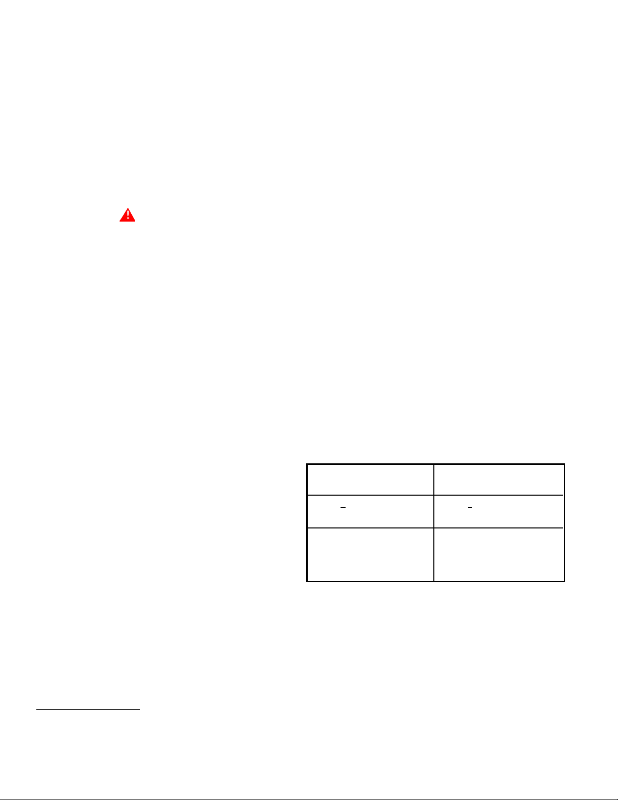
This is an example of calculating heater amperage for both
types of element operation. From this, the branch circuit
conductor and overcurrent protection sizing can be established.
The example is of a three-phase 240 volt unit with two, 6 kw
elements. The notations are for units field converted to
single-phase. Check the heater model and rating plate for actual
specifications and substitute those values in the following.
Non-simultaneous: Simultaneous:
(as factory wired) (Field conversion)
Voltage applied to the heater should not vary more than +5%
to -10% of the model and rating plate marking for satisfactory
operation.
DO NOT ENERGIZE THE BRANCH CIRCUIT FOR ANY REASON
BEFORE THE HEA TER T ANK IS FILLED WITH W A TER.
SO WILL CAUSE THE HEATING ELEMENTS TO BURN OUT.
The factory wiring is attached to a terminal block within the external
junction box unit. The branch circuit is connected to the terminal
block within this junction box. The water heater should be
connected to a separate, grounded, branch circuit with overcurrent
protection and disconnect switch. The water heater should be
grounded in accordance with national and local codes.
DOING
BRANCH CIRCUIT
The branch circuit wire size should be established through
reference to the current edition of NFPA-70, the
National Electrical Code or other locally approved source in
conjunction with the heater amperage rating. For convenience,
portions of the wire size tables from the Code are reproduced
here. The branch circuit should be sized at 125 percent of the
heater rating and further increase wire size as necessary to
compensate for voltage drop in long runs.
3000 : 240 = 12.5 amps* 3000 : 240 = 12.5 amps*
12.5 x 1.73 = 21.6 amps
*NOTE: as a single-phase *NOTE: as a single-phase
non-simultaneous unit. simultaneous unit the
total is:
12.5 x 2 = 25 amps
The rating of the overcurrent protection should be computed on
the basis of 125 percent of the total connected load amperage.
Where the standard ratings and settings do not correspond
with this computation, the next higher standard rating or setting
should be selected.
Portion of T able 310-16 (NFPA-70) follows:
Allowable Ampacities of Insulated Copper Conductors. Not
more than three conductors in Raceway or Cable or Direct Burial
(Based on Ambient Temperature of 30° C, 86° F).
These ampacities relate only to conductors described in Table
310-13 in Code.
For ambient temperatures over 30° C (86° F), see Correction
Factors, Note 13 in Code.
4
For ambient temperatures over 30° C (86° F), see Correction
Factors, Note 13 in Code.
Size Temperature Rating of Conductor
See Table 310-13 in Code
AMG 60° C 75° C
MCM (140° F) (167° F)
TYPES: TYPES:
RU W RH, RHW , RUH,
(14-2), (14-2), THW
T, TW, THWN, XHHW ,
UF USE
18 - - - - - 16 - - - - - 14 15 15
12 20 20
10 30 30
840 45
655 65
470 85
3 8 0 100
Portion of T able 310-18 follows:
Allowable Ampacities of Insulated Aluminum and Copper -Clad
Aluminum Conductors.
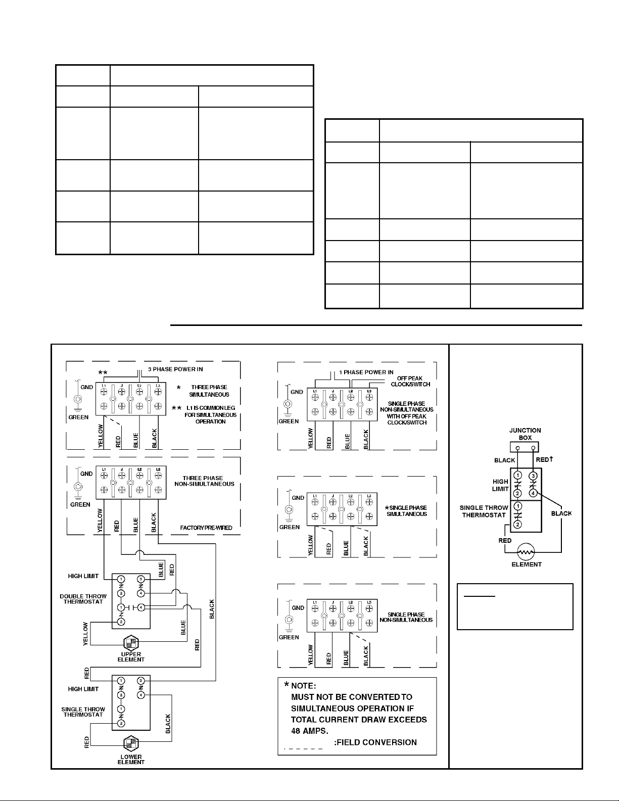
WIRING DIAGRAMS
Not more than three conductors in Raceway or Cable or Direct
Burial (Based on Ambient Temperature of 30° C, 86° F. These
ampacities relate only to conductors described in Table 310-13
in Code.
For ambient temperatures over 30° C (86° F), see Correction
Factors, Note 13 in Code.
Size Temperature Rating of Conductor
See Table 310-13 in Code
AMG 60° C 75° C
MCM (140° F) (167° F)
TYPES: TYPES:
RUW RH, RHW, RUH,
(12-2), (12-2), THW
T, TW, THWN, XHHW,
UF USE
12 15 15
10 25 25
830 40
640 50
455 65
365 75
275 90
1 85 100
A-8 CIRCUIT FOR DUAL ELEMENT HEA TER
C-2 CIRCUIT
FOR SINGLE
ELEMENT HEA TERS
EQUIPPED WITH HIGH
LIMIT CONTROL
FACTOR Y WIRED
---------- FIELD WIRING
† WHITE FOR 120V
5
 Loading...