

A.O. Smith ACI-CRS-24IL-N, ACI-CRS-24IL-P, ACI-CRS-26IL-N, ACI-CRS-26IL-P, ACI-CRS-36IL-N User Manual
...Page 1
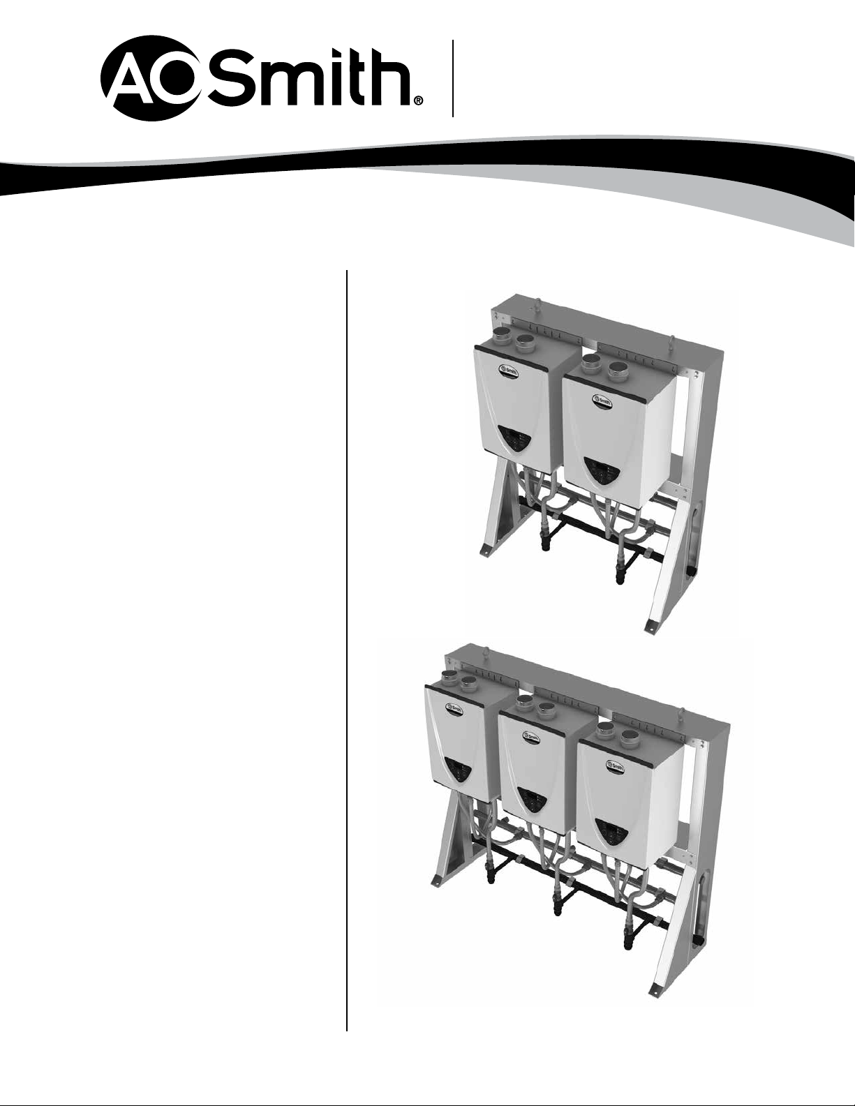
TANKLESS FREE STANDING IN-LINE
LIGHTWEIGHT
• Constructed of sturdy metal frame
• Utilizes the industry’s lightest 199,000 BTU
high efficiency condensing tankless heater
EXPANDABLE
• Multiple design and installation
configurations
• Up to 597,000 BTU on a single rack system
• Able to link up to 20 heaters together with
multi-link system
Commercial Tankless
Rack System
REDUNDANCY
• Multiple combustion systems provide peace
of mind
• Easily isolate a unit for maintenance which
extends the life of the heaters
EASY FIELD INSTALLATION
• Reduce installation costs with three simple
connections (cold water, hot water, and gas)
EASILY INTEGRATE STORAGE
• As the world’s largest water heater
manufacturer, we can easily integrate
storage into the design
WARRANTY
• 6 year heat exchanger
• 5 year parts
• 1-year limited warranty on rack parts
© July 2017 A. O. Smith Corporation. All Rights Reserved
www.hotwater.com | 800-527-1953 Toll-Free USA | A. O. Smith Corporation | 500 Tennessee Waltz Parkway | Ashland City, TN 37015
Page 1 of 5
AOSCG14003
Page 2
Commercial Tankless
Rack System
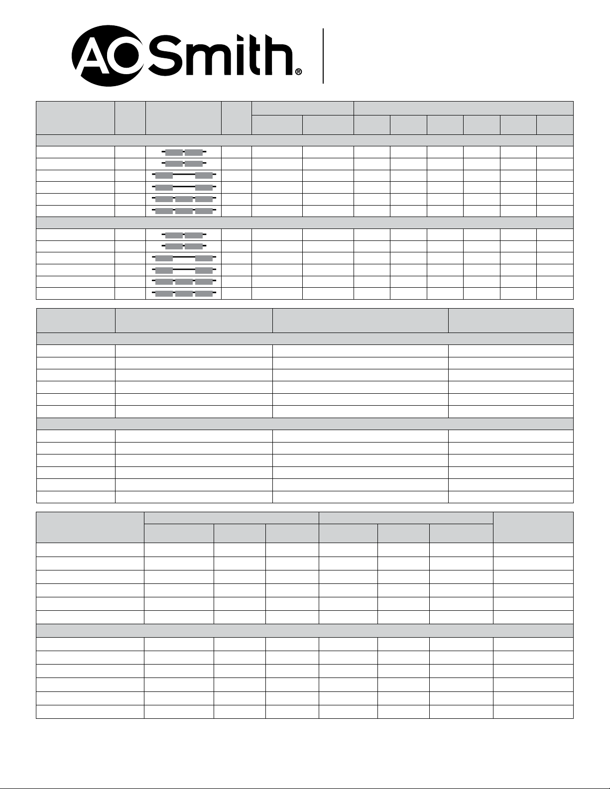
Model Number
Indoor Models
ACI-CRS-24IL-N 2 Natural 15,000 398,000 15.2 12.6 10.8 9.4 8.4 7.6
ACI-CRS-24IL-P 2 Propane 13,000 398,000 15.2 12.6 10.8 9.4 8.4 7.6
ACI-CRS-26IL-N 2 Natural 15,000 398,000 15.2 12.6 10.8 9.4 8.4 7.6
ACI-CRS-26IL-P 2 Propane 13,000 398,000 15.2 12.6 10.8 9.4 8.4 7.6
ACI-CRS-36IL-N 3 Natural 15,000 597,000 22.8 18.9 16.2 14.1 12.6 11.4
ACI-CRS-36IL-P 3 Propane 13,000 597,000 22.8 18.9 16.2 14.1 12.6 11.4
Outdoor Models
ACO-CRS-24IL-N 2 Natural 15,000 398,000 15.2 12.6 10.8 9.4 8.4 7.6
ACO-CRS-24IL-P 2 Propane 13,000 398,000 15.2 12.6 10.8 9.4 8.4 7.6
ACO-CRS-26IL-N 2 Natural 15,000 398,000 15.2 12.6 10.8 9.4 8.4 7.6
ACO-CRS-26IL-P 2 Propane 13,000 398,000 15.2 12.6 10.8 9.4 8.4 7.6
ACO-CRS-36IL-N 3 Natural 15,000 597,000 22.8 18.9 16.2 14.1 12.6 11.4
ACO-CRS-36IL-P 3 Propane 13,000 597,000 22.8 18.9 16.2 14.1 12.6 11.4
Model Number Gas Manifold Connection Hot/Cold Manifold Connection Power
Indoor Models
ACI-CRS-24IL-N 1-1/2” Schedule 40 pipe 2” Copper tube 120 V, 60 Hz, 4.5 A
ACI-CRS-24IL-P 1-1/2” Schedule 40 pipe 2” Copper tube 120 V, 60 Hz, 4.5 A
ACI-CRS-26IL-N 1-1/2” Schedule 40 pipe 2” Copper tube 120 V, 60 Hz, 6.75 A
ACI-CRS-26IL-P 1-1/2” Schedule 40 pipe 2” Copper tube 120 V, 60 Hz, 6.75 A
ACI-CRS-36IL-N 1-1/2” Schedule 40 pipe 2” Copper tube 120 V, 60 Hz, 6.75 A
ACI-CRS-36IL-P 1-1/2” Schedule 40 pipe 2” Copper tube 120 V, 60 Hz, 6.75 A
Outdoor Models
ACO-CRS-24IL-N 1-1/2” Schedule 40 pipe 2” Copper tube 120 V, 60 Hz, 4.5 A
ACO-CRS-24IL-P 1-1/2” Schedule 40 pipe 2” Copper tube 120 V, 60 Hz, 4.5 A
ACO-CRS-26IL-N 1-1/2” Schedule 40 pipe 2” Copper tube 120 V, 60 Hz, 6.75 A
ACO-CRS-26IL-P 1-1/2” Schedule 40 pipe 2” Copper tube 120 V, 60 Hz, 6.75 A
ACO-CRS-36IL-N 1-1/2” Schedule 40 pipe 2” Copper tube 120 V, 60 Hz, 6.75 A
ACO-CRS-36IL-P 1-1/2” Schedule 40 pipe 2” Copper tube 120 V, 60 Hz, 6.75 A
Number
of
Heaters
Configurations
Fuel
Type
Gas Consumption Input Max Flow (GPM)
Minimum
BTU/h
Maximum
BTU/h
50 F Rise 60 F Rise 70 F Rise 80 F Rise 90 F Rise 100 F Rise
Model Number
ACI-CRS-24IL-N 46 20 53.09 49.5 39 69.5 330
ACI-CRS-24IL-P 46 20 53.09 49.5 39 69.5 330
ACI-CRS-26IL-N 66 20 53.09 69.5 39 69.5 396
ACI-CRS-26IL-P 66 20 53.09 69.5 39 69.5 396
ACI-CRS-36IL-N 66 20 53.09 69.5 39 69.5 448
ACI-CRS-36IL-P 66 20 53.09 69.5 39 69.5 448
Outdoor Models
ACO-CRS-24IL-N 46 20 53.09 49.5 39 69.5 330
ACO-CRS-24IL-P 46 20 53.09 49.5 39 69.5 330
ACO-CRS-26IL-N 66 20 53.09 69.5 39 69.5 396
ACO-CRS-26IL-P 66 20 53.09 69.5 39 69.5 396
ACO-CRS-36IL-N 66 20 53.09 69.5 39 69.5 448
ACO-CRS-36IL-P 66 20 53.09 69.5 39 69.5 448
* Line drawings on pages 3 and 4.
Dimensions and specifications subject to change without notice in accordance with our policy of continuous product improvement.
Model numbers- First number 2/3/4/5/6 = number of tankless units mounted.
Model numbers - Second number 2/3/4/5/6 = rack size (max units that could fit on that rack).
Dimensions in Inches Shipping Dimensions in Inches
A
Length
B
Width
C
Height
Length Width Height
Approx. Shipping
Weight (lbs)
Page 2 of 5
AOSCG14003
Page 3

Commercial Tankless
Rack System
2 Unit Free Standing In-Line
Pipe Lengths:
53.09 in.
20.75 in.
(INLETS)
41.54 in.
SEE NOTE 1.
20.75 in.
(EXHAUSTS)
Front
Notes:
1. TOP-MOUNTED AIR SUPPLY INLET/EXHAUST VENT ARE USED WITH INDOOR MODELS ONLY.
2. INDOOR AND OUTDOOR RACK SYSTEMS HAVE IDENTICAL DIMENSIONS. EXCEPTION: INDOOR
MODELS HAVE TOP-MOUNTED INTAKES AND EXHAUSTS. OUTDOOR MODELS DO NOT.
Page 3 of 5
AOSCG14003
Page 4

Commercial Tankless
Front
Rack System
3 Unit Free Standing In-Line
Pipe Lengths:
53.09 in.
20.75 in.
(INLETS)
SEE NOTE 1.
20.75 in.
(EXHAUSTS)
62.29 in.
Notes:
1. TOP-MOUNTED AIR SUPPLY INLET/EXHAUST VENT ARE USED WITH INDOOR MODELS ONLY.
2. INDOOR AND OUTDOOR RACK SYSTEMS HAVE IDENTICAL DIMENSIONS. EXCEPTION: INDOOR
MODELS HAVE TOP-MOUNTED INTAKES AND EXHAUSTS. OUTDOOR MODELS DO NOT.
Page 4 of 5
AOSCG14003
Page 5

Commercial Tankless
Rack System
TANKLESS COMMERCIAL RACK SYSTEMS
The Tankless Commercial Rack System model # __________ shall be factory assembled pre-plumbed system and includes A. O. Smith CT-199
Condensing Tankless Water Heaters. The Commercial Rack System shall include 2 inch copper water supply lines, 2 foot long ¾ inch flexible stainless
steel water lines to the heaters, 1 ½ inch schedule 40 gas supply pipe with 3 foot long ¾ inch CSST flexible gas lines to the heaters, and isolation
valves with 150 psi pressure relief valves for each heater. The rack shall be assembled as an in-line floor standing design.
The fully modulating, on-demand, condensing gas fired tankless water heater(s) shall be A. O. Smith Tankless Water Heater model CT-199, having a
maximum input rating of 199,000 Btu/h and available in NG or LP. The heater shall have ¾ in. male NPT water and gas connections. The inlet gas
supply pressures shall be 4.0 in. WC (min.) up to 10.5 in. WC (max.) for NG and 8.0 in. WC (min.) up to 14 in. WC (max.) for LP. The indoor heater(s)
shall incorporate an integrated temperature controller that will provide diagnostic information, fault history, and heater set temperature. The outdoor
heater(s) shall be factory supplied with a temperature remote, 9009069005, that can be installed up to 400 ft. from the heater using 20 gauge
(minimum) control wire. The temperature remote shall provide diagnostic information, fault history, and additional temperature settings. The heater(s)
shall operate using 120 V / 60 Hz power source. The indoor heater(s) will incorporate a factory installed
power cord.
The indoor heater(s) shall be vented with 3” or 4” diameter schedule 40 PVC, CPVC, ABS, or Category IV vent pipe with a length not to exceed 70 ft.
(equivalent) for 3” vent or 100 ft. (equivalent) for 4” vent, terminating horizontally or vertically. The intake pipe may use material such as PVC, ABS,
aluminum, or Category IV pipe and cannot exceed 70 ft. (equivalent) for 3” vent or 100 ft. (equivalent) for 4” vent. The indoor heaters shall be able
to be common vented with schedule 40 PVC pipe with a length not exceed 100 ft. (equivalent) using up to10 inch pipe. Proper sizing is provided in
the heater’s installation manual. The outdoor heater(s) shall be constructed with an integral exhaust vent on the front of the heater.
The water heater(s) shall use a commercial grade copper, fin tube primary heat exchanger with quick release brass or bronze waterways. The
secondary heat exchanger shall be constructed from stainless steel 316L. The heater(s) shall be controlled by an onboard solid-state printed circuit
board which uses the following factory installed components: thermistors to monitor water temperature and exhaust temperature; a flow sensor
to measure flow rate; a flame sensor to monitor combustion; an air-fuel ratio rod to measure and adjust air inputs in order to maintain optimal
combustion efficiency. The heater also consists of in-line fusing and surge absorbers for electrical surge protection, an electronic spark igniter,
aluminized stainless steel burners, hi-limit temperature switches to monitor water and exhaust temperatures, modulating gas valve, dual freeze
protection that will automatically fire the heater (indoor model only) and use heating blocks to protect the heat exchanger, and an overheat
cutoff fuse.
The heaters can manifold to Easy-Link up to 4 heaters to provide additional capacity. The Easy-Link controls shall be built onto the onboard solidstate printed circuit board and does not require external controls. The linking control wire shall be supplied with the heater. The heaters can use
a Multi-Unit controller, 9008300005, to manifold 5-20 heaters. The Easy-Link and Multi-Unit Controller shall modulate the system for the most
efficient performance. The Easy-Link and Multi-Unit Controller shall rotate the priority heater every 12 hours of operation time or 100 starts for
balanced duty/cycle operation.
The heater models are design certified by CSA according to ANSI Z21.10.3-2013, approved for sale in the United States, ENERGY STAR® qualified,
has a minimum energy factor of 0.95, meets the energy efficiency requirements of the U. S. Department of Energy and ASHRAE 90.1, complies with
SCAQMD Rule 1146.2 and other air quality districts with similar requirements for low NOx emissions of 14 ng/J or 20 ppm, and shall be certified to
NSF 5 Standards.
For Technical Information call 800-527-1953. A. O. Smith Corporation reserves the right to make product changes or improvements without prior notice.
© July 2017 A. O. Smith Corporation. All Rights Reserved
www.hotwater.com | 800-527-1953 Toll-Free USA | A. O. Smith Corporation | 500 Tennessee Waltz Parkway | Ashland City, TN 37015
Page 5 of 5
AOSCG14003
 Loading...