

Page 1
100298550_2000552608_Rev B
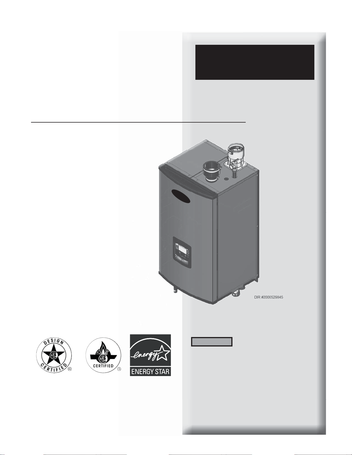
ProLine® XE
Combi Boiler
ProLine® XE Combi Boiler
Installation & Service Manual
Models: 110 - 150 - 199
WARNING
Save this manual for future reference.
This manual must only be used
by a qualified heating installer
/ service technician. Read all
instructions, in this manual before
installing. Perform steps in the
order given. Failure to comply
could result in severe personal
injury, death, or substantial
property damage.
Page 2

Contents
HAZARD DEFINITIONS................................................................. 2
PLEASE READ BEFORE PROCEEDING .............................. 3
THE COMBI BOILER -- HOW IT WORKS ............................... 4-5
RATINGS ............................................................................................ 6
1. DETERMINE BOILER LOCATION
Provide Clearances .............................................................................. 7
Provide Air Openings to Room ......................................................... 9
Wall Mounting Location ................................................................... 9
Residential Garage Installation .......................................................... 9
Vent and Air Piping ............................................................................ 9
Prevent Combustion Air Contamination ........................................ 9
Corrosive Contaminants and Sources ............................................ 10
Using an Existing Vent System to Install a New Boiler ............... 10
Removing a Boiler from Existing Common Vent ........................ 11
2. PREPARE BOILER
Remove Boiler from Wood Pallet ................................................... 12
Gas Conversions .......................................................................... 12-13
Mounting the Boiler .......................................................................... 13
3. GENERAL VENTING
Direct Venting Options .................................................................... 14
Install Vent and Combustion Air Piping ....................................... 15
Sizing ................................................................................................... 16
Max. Allowable Vent Piping Lengths ............................................. 16
Materials .............................................................................................. 16
Optional Room Air ............................................................................ 17
PVC/CPVC ......................................................................................... 18
Polypropylene ......................................................................................19
Stainless Steel Vent ............................................................................ 20
4. SIDEWALL DIRECT VENTING
Vent/Air Termination - Sidewall .............................................. 21-23
Determine Location ............................................................... 21-22
Prepare Wall Penetrations .......................................................... 23
Multiple Vent/Air Terminations ..................................................... 23
Sidewall Termination - Optional Concentric Vent ................ 24-26
5. VERTICAL DIRECT VENTING
Vent/Air Termination - Vertical ............................................... 27-28
Determine Location ..................................................................... 27
Prepare Roof Penetrations .......................................................... 28
Multiple Vent/Air Terminations ..................................................... 28
Vertical Termination - Optional Concentric Vent ................. 29-30
Alternate Vertical Concentric Venting .................................... 31-32
6A. HYDRONIC PIPING
System Water Piping Methods ........................................................ 33
Low Water Cutoff Device ................................................................. 33
Chilled Water System ........................................................................ 33
Freeze Protection ............................................................................... 33
General Piping Information ............................................................. 33
Near Boiler Piping Components ..................................................... 34
Hydronic Piping Diagrams ......................................................... 36-39
6B. DOMESTIC WATER PIPING
Scalding ............................................................................................... 40
Water Chemistry ................................................................................ 40
Near Heater Piping Components .................................................... 40
Domestic Water Piping Diagrams ............................................ 41-43
7. GAS CONNECTIONS
Connecting Gas Supply Piping ........................................................ 44
Natural Gas ......................................................................................... 45
Pipe Sizing for Natural Gas ........................................................ 45
Natural Gas Supply Pressure Requirements ............................ 45
Propane Gas ........................................................................................ 45
Pipe Sizing for Propane Gas ....................................................... 45
Propane Supply Pressure Requirements ................................... 45
Check Inlet Gas Supply ............................................................... 46-47
Gas Pressure ....................................................................................... 47
Gas Valve Replacement .................................................................... 47
8. FIELD WIRING
Line Voltage Connections ................................................................ 48
Low Voltage Connections ................................................................ 48
9. CONDENSATE DISPOSAL
Condensate Drain .............................................................................. 51
10. STARTUP ............................................................................ 52-60
11. OPERATING INFORMATION
General ................................................................................................ 61
Menus ............................................................................................. 61-62
Control Inputs and Outputs .......................................................63-64
Cascade ................................................................................................. 65
Protection Features ....................................................................... 65-66
Sequence of Operation ................................................................ 66-68
12. MAINTENANCE
Maintenance and Annual Startup ............................................. 69-75
13. TROUBLESHOOTING .................................................... 76-87
14. DIAGRAMS
Ladder Diagram (Standard) ............................................................. 88
Wiring Diagram (Standard) ............................................................. 89
Revision Notes .................................................................... Back Cover
Hazard definitions
The following defined terms are used throughout this manual to bring attention to the presence of hazards of various risk levels or
to important information concerning the life of the product.
DANGER
WARNING
CAUTION
CAUTION
NOTICE
2
DANGER indicates an imminently hazardous situation which, if not avoided, will result in death or serious
injury.
WARNING indicates a potentially hazardous situation which, if not avoided, could result in death or serious
injury.
CAUTION indicates a potentially hazardous situation which, if not avoided, may result in minor or moderate
injury.
CAUTION used without the safety alert symbol indicates a potentially hazardous situation which, if not
avoided, may result in property damage.
NOTICE indicates special instructions on installation, operation, or maintenance that are important but not
related to personal injury or property damage.
Page 3
Please read before proceeding
ProLine® XE
Combi Boiler
Installation & Service Manual
WARNING
NOTICE
WARNING
WARNING
Installer – Read all instructions, in this
manual before installing. Perform steps
in the order given.
User – This manual is for use only
by a qualified heating installer/
service technician. Refer to the User’s
Information Manual for your reference.
Have this boiler serviced/inspected by
a qualified service technician, at least
annually.
Failure to comply with the above could
result in severe personal injury, death or
substantial property damage.
When calling or writing about the boiler
– Please have the boiler model and serial
number from the boiler rating plate.
Consider piping and installation when
determining boiler location.
Any claims for damage or shortage in
shipment must be filed immediately
against the transportation company by
the consignee.
Factory warranty (shipped with unit) does
not apply to units improperly installed or
improperly operated.
Failure to adhere to the guidelines on this
page can result in severe personal injury,
death, or substantial property damage.
If the information in this manual is not
followed exactly, a fire or explosion may
result causing property damage, personal
injury or loss of life.
This appliance MUST NOT be installed in
any location where gasoline or flammable
vapors are likely to be present.
WHAT TO DO IF YOU SMELL GAS
WARNING
DO NOT install units in rooms or
environments that contain corrosive
contaminants (see Table 1A on page 10).
Failure to comply could result in severe
personal injury, death, or substantial
property damage.
When servicing boiler –
• To avoid electric shock, disconnect electrical supply
before performing maintenance.
• To avoid severe burns, allow boiler to cool before
performing maintenance.
Boiler operation –
• Do not block flow of combustion or ventilation air to
the boiler.
• Should overheating occur or gas supply fail to shut off,
do not turn off or disconnect electrical supply to
circulator. Instead, shut off the gas supply at a location
external to the appliance.
• Do not use this boiler if any part has been under water.
The possible damage to a flooded appliance can be
extensive and present numerous safety hazards. Any
appliance that has been under water must be replaced.
Boiler water –
• Thoroughly flush the system to remove debris. Use
an approved pre-commissioning cleaner (see Start-Up
Section), without the boiler connected, to clean the
system and remove sediment. The high efficiency heat
exchanger can be damaged by build-up or corrosion
due to sediment.
NOTE: Cleaners are designed for either new systems or
pre-existing systems. Choose accordingly.
Freeze protection fluids –
• NEVER use automotive antifreeze. Use only inhibited
propylene glycol solutions, which are specifically
formulated for hydronic systems. Ethylene glycol is
toxic and can attack gaskets and seals used in hydronic
systems.
• Do not try to light any appliance.
• Do not touch any electric switch; do
not use any phone in your building.
• Immediately call your gas supplier
from a near by phone. Follow the
gas supplier’s instructions.
• If you cannot reach your gas supplier,
call the fire department.
• Installation and service must be
performed by a qualified installer,
service agency, or the gas supplier.
3
Page 4

ProLine® XE
Combi Boiler
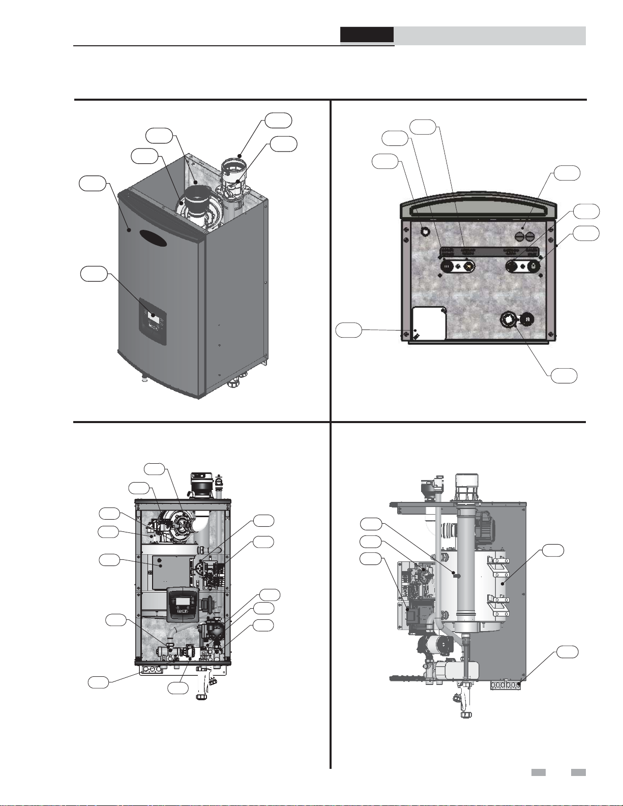
The Combi Boiler - How it works...
Installation & Service Manual
1. Heat exchanger
Allows system water to flow through specially designed
coils for maximum heat transfer, while providing
protection against flue gas corrosion. The coils are
encased in a jacket that contains the combustion process.
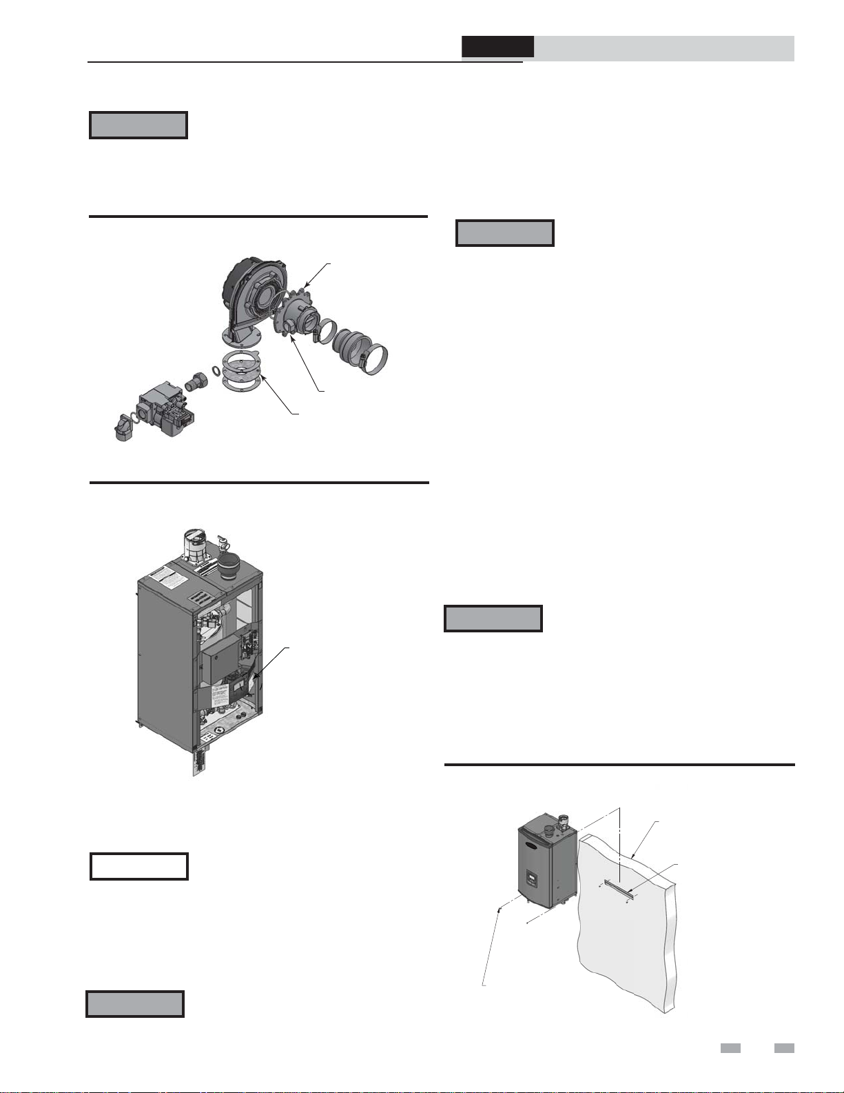
2. Blower
The blower pulls in air and gas through the venturi (item
5). Air and gas mix inside the blower and are pushed into the
burner, where they burn inside the combustion chamber.
3. Gas valve
The gas valve senses the negative pressure created by the
blower, allowing gas to flow only if the gas valve is
powered and combustion air is flowing.
4. Venturi
The venturi controls air and gas flow into the burner.
5. Flue gas sensor (limit rated)
This sensor monitors the flue gas exit temperature. The control
module will modulate and shut down the boiler if flue gas
temperature gets too hot. This protects the flue pipe from
overheating.
6. Boiler outlet temperature sensor (limit rated)
This sensor monitors boiler outlet water temperature (system
supply). The control module will adjust boiler firing rate so the
outlet temperature is correct.
7. Boiler inlet temperature sensor
This sensor monitors return water temperature (system
return).
8. Temperature and pressure gauge (field installed, not
shown)
Monitors the outlet temperature of the boiler as well as the
system water pressure.
9. Electronic LCD display
The electronic display consists of five (5) buttons, and a liquid
crystal display. The display is used to make adjustments and
read boiler status.
10. Flue pipe adapter
Allows for the connection of the vent pipe system to the
boiler.
11. Burner (not shown)
Made with metal fiber and stainless steel construction,
the burner uses pre-mixed air and gas and provides a
wide range of firing rates.
12. Boiler water outlet
The boiler water outlet is the boiler water connection for water
leaving the boiler and entering the system.
13. DHW water outlet
The DHW water outlet is the DHW water connection for water
leaving the boiler and entering the system.
14. Boiler water inlet
The boiler water inlet is the boiler water connection for water
entering the boiler from the system.
15. DHW water inlet
The DHW water inlet is the DHW water connection for water
entering the boiler from the system.
16. Gas connection pipe
Threaded pipe connection of 1/2". This pipe should be
connected to the incoming gas supply for the purpose of
delivering gas to the boiler.
17. Boiler control module
The boiler control responds to internal and external signals
and controls the blower, gas valve, and pumps to meet the
demand.
18. Air intake adapter
Allows for the connection of the air intake pipe to
the boiler.
19. High voltage junction box
The junction box contains the connection points for the line
voltage power and all pumps.
20. Low voltage connection board
The connection board is used to connect external low voltage
devices.
21. Low voltage wiring connections
Conduit connection points for the low voltage
connection board.
22. Condensate drain connection
The condensate drain connection provides a connection
point to install a condensate drain line.
23. Front access cover
Provides access to all internal components.
24. Ignition / flame sense electrode
Used by the control module to detect the presence of burner
flame.
25. Flame inspection window
The quartz glass window provides a view of the burner
surface and flame.
26. Relief valve
Protects the heat exchanger from an over pressure condition.
The relief valve provided with the unit is set at 50 psi.
27. Line voltage wiring connections (inside junction box)
Conduit connection points for the high voltage junction box.
28. Air pressure switch
The air pressure switch detects blocked conditions.
29. Transformer
The transformer provides 24V power to the integrated control.
30. Pump with automatic air vent
Provides flow through the unit for space heating and domestic
water applications. Serves as the boiler and DHW pump.
31. Diverter valve
Diverts boiler water from the heating loop to the DHW heat
exchanger.
32. Flow switch
The flow switch detects a DHW draw, and signals the
boiler to fire.
33. DHW sensor
This sensor monitors DHW water temperature.
The control module will adjust boiler firing rate so the
DHW temperature is correct.
4
Page 5
ProLine® XE
Combi Boiler
Installation & Service Manual
The Combi Boiler - How it works... (continued)
18
2
23
9
Front Outside View
10
26
DIR #2000528036
16
LEFT RIGHT
19
DIR #2000528036 00
Bottom View
12
13
FRONT
BACK
21
15
14
22
3
25
24
17
6
33
Front Inside View
4
28
20
30
32
7
DIR #2000528036 00
31
5
28
1
29
27
DIR #2000528036 00
Side_Rear View
5
Page 6
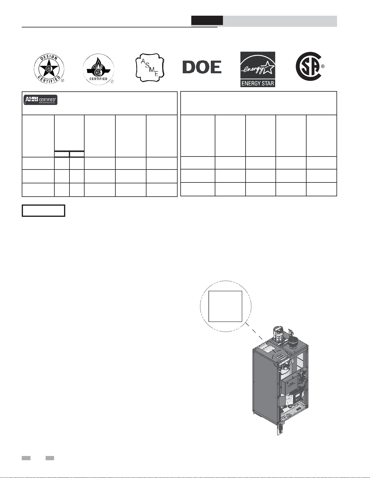
Ratings
A
S
M
E
H
ProLine® XE
Combi Boiler
Installation & Service Manual
LOW LEAD CONTENT
Combi
AHRI Rating
Model Number
Note: Change “N”
to “L” for L.P. gas
models.
110(N,L) 11 110 102 89 95.0
150(N,L) 15 150 139 121 95.0
199(N,L) 20 199 185 161 95.0
NOTICE
Input
MBH
(Note 5)
Min
Max
Maximum allowed working pressure is located on the rating plate.
Heating
Capacity
MBH
(Note 2, 7)
Net
AHRI
Ratings
Water,
MBH
(Note 3, 7)
Notes:
1. As an Energy Star Partner, the manufacturer has determined
that Combi Boilers meet the Energy Star guidelines for
energy efficiency.
2. The ratings are based on standard test procedures prescribed
by the United States Department of Energy.
3. Net AHRI ratings are based on net installed radiation of
sufficient quantity for the requirements of the building
and nothing need be added for normal piping and pickup.
Ratings are based on a piping and pickup allowance of 1.15.
4. Combi Boilers require special gas venting. Use only the
vent materials and methods specified in the Combi Boiler
Installation and Service Manual.
5. Standard Combi Boilers are equipped to operate from sea
level to 4,500 feet only with no adjustments. The boiler will
de-rate by 4% for each 1,000 feet above sea level up to 4,500
feet.
6. High altitude Combi Boilers are equipped to operate from
3,000 to 9,600 feet only. The boiler will not de-rate up to
5,000 feet and will de-rate 4.45% for each 1,000 feet above
5,000 feet. The operation given in this manual remains the
same as the standard boilers. A high altitude label (as shown
in FIG. A) is also affixed to the unit.
De-rate values are based on proper combustion calibration
and
CO2’s adjusted to the recommended levels.
AFUE
%
(Note 1, 7)
Other Specifications
Boiler Water
Content Gallons
1.4 1" 3/4" 1/2" 3"
2.0 1" 3/4" 1/2" 3"
2.7 1" 3/4" 1/2" 3"
SH Water
Connections
DHW Water
Connections
Gas
Connections
7. Ratings have been confirmed by the Hydronics Institute,
Section of AHRI.
8. The manual reset high limit provided with the Combi
Boiler is listed to UL353.
UNIT EQUIPPED FOR
HIGH ALTITUDE
3,000 FT. TO 9,600 FT.
Vent/Air
Size
(Note 4)
For installations above 9,600 feet, please consult the factory.
Figure A High Altitude Label Location
6
Page 7

1 Determine boiler location
ProLine® XE
Combi Boiler
Installation & Service Manual
Installation must comply with:
• Local, state, provincial, and national codes, laws,
regulations, and ordinances.
• National Fuel Gas Code, ANSI Z223.1 – latest edition.
• National Electrical Code.
• For Canada only: B149.1 Installation Code, CSA C22.1
Canadian Electrical Code Part 1 and any local codes.
NOTICE
The Combi Boiler gas manifold and
controls met safe lighting and other
performance criteria when the boiler
underwent tests specified in ANSI Z21.13
– latest edition.
Before locating the boiler, check:
1. Check for nearby connection to:
• System water piping
• Venting connections
• Gas supply piping
• Electrical power
2. Locate the appliance so that if water connections should
leak, water damage will not occur. When such locations
cannot be avoided, it is recommended that a suitable
drain pan, adequately drained, be installed under the
appliance. The pan must not restrict combustion air
flow. Under no circumstances is the manufacturer to be
held responsible for water damage in connection with
this appliance, or any of its components.
3. Check area around the boiler. Remove any combustible
materials, gasoline and other flammable liquids.
WARNING
4. The Combi Boiler must be installed so that gas control
system components are protected from dripping or
spraying water or rain during operation or service.
5. If a new boiler will replace an existing boiler, check for
and correct system problems, such as:
• System leaks causing oxygen corrosion or heat
exchanger cracks from hard water deposits.
• Incorrectly-sized expansion tank.
• Lack of freeze protection in boiler water causing system
and boiler to freeze and leak.
• Debris left from existing piping, if not flushed and
cleaned with an appropriate cleaner.
6. Check around the boiler for any potential air
contaminants that could risk corrosion to the boiler or
the boiler combustion air supply (see Table 1A on page
10). Prevent combustion air contamination. Remove
any of these contaminants from the boiler area.
WARNING
Failure to keep boiler area clear and free
of combustible materials, gasoline, and
other flammable liquids and vapors can
result in severe personal injury, death, or
substantial property damage.
DO NOT install units in rooms or
environments that contain corrosive
contaminants (see Table 1A on page 10).
Failure to comply could result in severe
personal injury, death, or substantial
property damage.
WARNING
WARNING
This appliance is certified as an indoor
appliance. Do not install the appliance
outdoors or locate where the appliance will
be exposed to freezing temperatures or to
temperatures that exceed 100°F.
Failure to install the appliance indoors
could result in severe personal injury,
death, or substantial property damage.
This appliance requires a special venting
system. The vent connection to the
appliance is made of CPVC. Field supplied
vent fittings must be cemented to the CPVC
fitting on the boiler. Use only the vent
materials, primer, and cement specified in
the manual to make the vent connections.
Failure to follow this warning could result
in fire, personal injury, or death.
Closet and alcove installations
A closet is any room the boiler is installed in which is less
than 93 cubic feet for 110 models, and 102 cubic feet for 150
- 199 models.
An alcove is any room which meets the criteria for a closet
with the exception that it does not have a door.
Example: Room dimensions = 4 feet long, 3 feet wide, and
7 foot ceiling = 4 x 3 x 7 = 84 cubic feet. This would be
considered a closet for a Combi Boiler.
WARNING
For closet and alcove installations as
shown in FIG.’s 1-1 and 1-2, CPVC,
polypropylene or stainless steel vent
material must be used inside the structure.
The two ventilating air openings shown in
FIG. 1-1 are required for this arrangement.
Failure to follow this warning could result
in fire, personal injury, or death.
Provide clearances:
Clearances from combustible materials
1. Hot water pipes—at least 1/4" from combustible materials.
2. Vent pipe – at least 1" from combustible materials.
3. See FIG.’s 1-1 and 1-2 on page 8 for other clearance
minimums.
Clearances for service access
1. See page 9 for recommended service clearances. If you
do not provide the minimum clearances shown, it may
not be possible to service the boiler without removing it
from the space.
7
Page 8
A
1 Determine boiler location
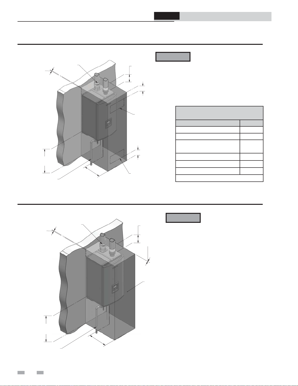
Figure 1-1 Closet Installation - Minimum Required Clearances
LEFT
0"
MINIMUM
1" MINIMUM CLEARANCE
AROUND VENT PIPE
TOP
6"
MINIMUM
6"
ProLine® XE
Combi Boiler
WARNING
Installation & Service Manual
For closet installations, CPVC,
polypropylene, or stainless steel
vent material MUST BE used in
a closet structure due to elevated
temperatures. Failure to follow
this warning could result in fire,
personal injury, or death.
VENTING*
OPENING
BOTTOM
0"
MINIMUM
1/4"MINIMUM CLEARANCE
ROUND HOT WATER PIPES
FRONT
6"
MINIMUM
6"
VENTING*
OPENING
DIR #2000534543 00
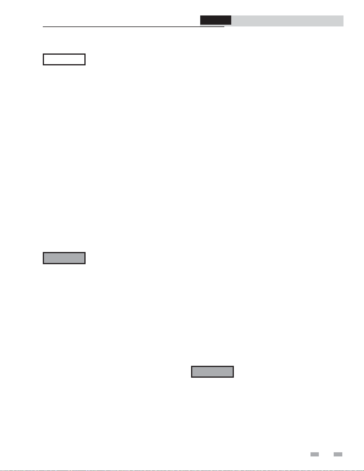
Figure 1-2 Alcove Installation - Minimum Required Clearances
1" MINIMUM CLEARANCE
LEFT
0"
MINIMUM
AROUND VENT PIPE
TOP
6"
MINIMUM
Minimum Clearances to Combustible
Materials
Location Clearances
From Top of the Unit 6"
From Front of the Unit 6"
From Flue or Vent Connector
in any Direction
From Back of the Unit 0"
From the Left Side of the Unit 0"
From the Right Side of the Unit 0"
Type of Floor - Combustible
Note: Service clearances are recommendations only.
WARNING
For alcove installations, CPVC,
polypropylene, or stainless steel
vent material MUST BE used in
an alcove structure due to elevated
temperatures. Failure to follow
RIGHT
0" MINIMUM
this warning could result in fire,
personal injury, or death.
1"
OPEN DOOR
BOTTOM
0"
MINIMUM
1/4"MINIMUM CLEARANCE
AROUND HOT WATER PIPES
FRONT
6"
MINIMUM
DIR #2000534544 00
Note: Service clearances are recommendations only.
8
Page 9
ProLine® XE
Combi Boiler
1 Determine boiler location (continued)
Installation & Service Manual
NOTICE
Recommended clearances for service access
- Front ............................................................................. 24"
- Left ................................................................................ 12"
- Right ............................................................................. 12"
- Bottom .......................................................................... 24"
If you do not provide the recommended
service clearances shown, it may not be
possible to service the boiler without
removing it from the space.
Provide air openings to room:
Boiler alone in boiler room
1. No air ventilation openings into the boiler room are
needed when clearances around the Combi Boiler are
at least equal to the SERVICE clearances shown in
FIG.’s 1-1 and 1-2. For spaces that do NOT supply this
clearance, provide two openings as shown in FIG. 1-1.
Each opening must provide one square inch free area
per 1,000 Btu/hr of boiler input.
Boiler in same space with other gas or oil-fired
appliances
1. Follow the National Fuel Gas Code (U.S.) or CSA
B149.1 (Canada) to size/verify size of the combustion/
ventilation air openings into the space.
WARNING
2. Size openings only on the basis of the other appliances
in the space. No additional air opening free area
is needed for the Combi Boiler because it takes its
combustion air from outside (direct vent installation).
The space must be provided with
combustion/ventilation air openings
correctly sized for all other appliances
located in the same space as the Combi
Boiler.
Do not install the boiler in an attic.
Failure to comply with the above
warnings could result in severe personal
injury, death, or substantial property
damage.
Wall mounting location
Ensure the wall for which the boiler is intended to be
mounted is comprised of either, cement, brick, block, or
wooden studs spaced 16" apart from center. Ensure the
wall is capable of supporting at least 200 pounds.
If flooding is possible, elevate the boiler sufficiently to
prevent water from reaching the boiler.
Ensure the boiler is installed in a location that minimizes
the risk of water damage due to valves, pumps, etc.
Residential garage installation
Precautions
Take the following precautions when installing the appliance in
a residential garage. If the appliance is located in a residential
garage, it should be installed in compliance with the latest
edition of the National Fuel Gas Code, ANSI Z223.1 and/or
CAN/CGA-B149 Installation Code.
• Appliances located in residential garages and in
adjacent spaces that open to the garage and are not part
of the living space of a dwelling shall be installed so that
all burners and burner ignition devices are located not
less than 18 inches (46 cm) above the floor.
• The appliance shall be located or protected so that it is
not subject to physical damage by a moving vehicle.
Vent and air piping
The Combi Boiler requires a special vent system, designed for
pressurized venting.
The boiler is to be used for either direct vent installation or for
installation using indoor combustion air. When room air is
considered, see Section 3, General Venting. Note prevention of
combustion air contamination below when considering vent/
air termination.
Vent and air must terminate near one another and may be
vented vertically through the roof or out a side wall, unless
otherwise specified. You may use any of the vent/air piping
methods covered in this manual. Do not attempt to install the
Combi Boiler using any other means.
Be sure to locate the boiler such that the vent and air piping can
be routed through the building and properly terminated. The
vent/air piping lengths, routing and termination method must
all comply with the methods and limits given in this manual.
Prevent combustion air contamination
Install air inlet piping for the Combi Boiler as described in
this manual. Do not terminate vent/air in locations that can
allow contamination of combustion air. Refer to Table 1A,
page 10 for products and areas which may cause contaminated
combustion air.
WARNING
You must pipe combustion air to the boiler
air intake. Ensure that the combustion air will
not contain any of the contaminants in Table
1A, page 10. Contaminated combustion air
will damage the boiler, resulting in possible
severe personal injury, death or substantial
property damage. Do not pipe combustion
air near a swimming pool, for example.
Also, avoid areas subject to exhaust fumes
from laundry facilities. These areas will
always contain contaminants.
9
Page 10
1 Determine boiler location
ProLine® XE
Combi Boiler
Installation & Service Manual
Table 1A Corrosive Contaminants and Sources
Products to avoid:
Spray cans containing chloro/fluorocarbons
Permanent wave solutions
Chlorinated waxes/cleaners
Chlorine-based swimming pool chemicals
Calcium chloride used for thawing
Sodium chloride used for water softening
Refrigerant leaks
Paint or varnish removers
Hydrochloric acid/muriatic acid
Cements and glues
Antistatic fabric softeners used in clothes dryers
Chlorine-type bleaches, detergents, and cleaning solvents
found in household laundry rooms
Adhesives used to fasten building products and other
similar products
Areas likely to have contaminants
Dry cleaning/laundry areas and establishments
Swimming pools
Metal fabrication plants
Beauty shops
When using an existing vent system to
install a new boiler:
WARNING
Check the following venting components before installing:
• Material - For materials listed for use with this appliance,
see Section 3 - General Venting.
• Size - To ensure proper pipe size is in place, see Table 3A.
Check to see that this size is used throughout the vent
system.
• Manufacturer - For a polypropylene or stainless steel
application, you must use only the listed manufacturers
and their type product listed in Tables 3D and 3F for CAT
IV positive pressure venting with flue producing
condensate.
• Supports - Non-combustible supports must be in place
allowing a minimum 1/4" rise per foot. The supports
should adequately prevent sagging and vertical slippage,
by distributing the vent system weight. For additional
information, consult the vent manufacturer’s
instructions for installation.
• Terminations - Carefully review Sections 3 through 5 to
ensure requirements for the location of the vent and air
terminations are met and orientation of these fit the
appropriate image from the Sidewall or Vertical
options listed in the General Venting Section. For
stainless steel vent, only use terminations listed in Table
3B for the manufacturer of the installed vent.
Failure to follow all instructions can result
in flue gas spillage and carbon monoxide
emissions, causing severe personal injury
or death.
Refrigeration repair shops
Photo processing plants
Auto body shops
Plastic manufacturing plants
Furniture refinishing areas and establishments
New building construction
Remodeling areas
Garages with workshops
10
• Seal - With prior requirements met, the system should be
tested to the procedure listed in parts (c) through (f) of
the Removal of an Existing Boiler Section on page 11.
With polypropylene and stainless steel vent, seal and connect
all pipe and components as specified by the vent manufacturer
used; with PVC/CPVC vent, see the Installing Vent or Air
Piping Section on page 18.
WARNING
If any of these conditions are not met,
the existing system must be updated or
replaced for that concern. Failure to
follow all instructions can result in flue gas
spillage and carbon monoxide emissions,
causing severe personal injury or death.
Page 11

ProLine® XE
Combi Boiler
Installation & Service Manual
1 Determine boiler location (continued)
When removing a boiler from existing common vent system:
DANGER
WARNING
At the time of removal of an existing boiler, the following steps
shall be followed with each appliance remaining connected
to the common venting system placed in operation, while the
other appliances remaining connected to the common venting
system are not in operation.
a. Seal any unused openings in the common venting system.
b. Visually inspect the venting system for proper size and
horizontal pitch and determine there is no blockage or
restriction, leakage, corrosion, or other deficiencies, which
could cause an unsafe condition.
c. Test vent system – Insofar as is practical, close all building
doors and windows and all doors between the space in
which the appliances remaining connected to the common
venting system are located and other spaces of the building.
Turn on clothes dryers and any appliance not connected
to the common venting system. Turn on any exhaust fans,
such as range hoods and bathroom exhausts, so they will
operate at maximum speed. Do not operate a summer
exhaust fan. Close fireplace dampers.
Do not install the Combi Boiler into a
common vent with any other appliance.
This will cause flue gas spillage or appliance
malfunction, resulting in possible severe
personal injury, death, or substantial
property damage.
Failure to follow all instructions can result
in flue gas spillage and carbon monoxide
emissions, causing severe personal injury
or death.
g. Any improper operation of the common venting system
should be corrected so the installation conforms with
the National Fuel Gas Code, ANSI Z223.1/NFPA 54
and/or CAN/CSA B149.1, Natural Gas and Propane
Installation Code. When resizing any portion of the
common venting system, the common venting system
should be resized to approach the minimum size as
determined using the appropriate tables in Part 11
of the National Fuel Gas Code, ANSI Z223.1/NFPA
and/or CAN/CSA B149.1, Natural Gas and Propane
Installation Code.
d. Place in operation the appliance being inspected. Follow
the lighting instructions. Adjust thermostat so appliance
will operate continuously.
e. Test for spillage at the draft hood relief opening after
5 minutes of main burner operation. Use the flame of a
match or candle, or smoke from a cigarette, cigar, or pipe.
f. After it has been determined that each appliance remaining
connected to the common venting system properly vents
when tested as outlined herein, return doors, windows,
exhaust fans, fireplace dampers, and any other gas-burning
appliance to their previous conditions of use.
11
Page 12
2 Prepare boiler
ProLine® XE
Combi Boiler
Installation & Service Manual
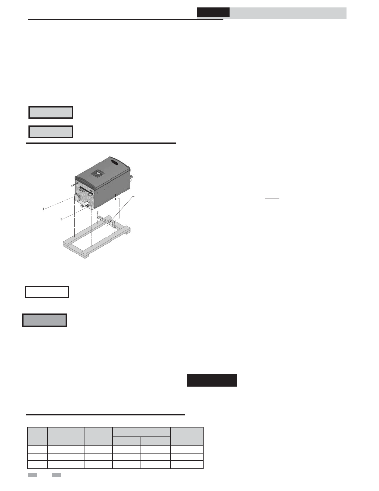
Remove boiler from wood pallet
1. After removing the outer shipping carton from the
boiler, remove the parts box.
2. To remove the boiler from the pallet:
a. Remove the two (2) lag bolts securing the
bottom of the unit to the pallet.
b. Lift the boiler off the wall bracket mounted to
the pallet (FIG. 2-1).
CAUTION
Do not attempt to use the water pipe
fittings or gas pipe to lift the boiler.
CAUTION
Do not attempt to lift the boiler using the
gas pipe as a handle.
Figure 2-1 Boiler Mounted on Shipping Pallet
REMOVE SHIPPING
(WALL) BRACKET
DO NOT DISCARD.
WILL BE NEEDED TO
SECURE THE BOILER
TO THE WALL.
DIR #2000528206 00
3. Remove the two (2) lag bolts securing the wall bracket to the
wood pallet. Be certain not to lose the wall bracket as it will
be needed for securing the boiler to the wall (FIG. 2-4).
NOTICE
Do not drop the boiler. Damage to the
boiler can result.
Gas conversions
WARNING
You must install a propane venturi to operate the Combi
Boiler on propane gas. Verify when installing that the venturi
label marking matches the boiler size (see Table 2A).
Table 2A LP Conversion Table
Model Kit #
110 100296965 20 mm 2.45 mm 2.55 mm 100150947
150 100296966 24 mm 3.20 mm 2.95 mm 100150472
199 100296970 24 mm 3.30 mm 3.10 mm 100150434
For a boiler already installed, you must
turn off gas supply, turn off power and
allow boiler to cool before proceeding.
You must also completely test the boiler
after conversion to verify performance as
described under Start-up, Section 10 of
this manual.
Failure to comply could result in severe
personal injury, death, or substantial
property damage.
Venturi Ø
(mm)
Orifice Ø
Bottom Top
1. If boiler is already installed, you must turn off the gas
supply, turn off the power, and allow the boiler to cool
before proceeding.
2. Remove the front access cover from the unit (no tools
required for removal).
3. Using a 5/16" nut driver, loosen the rachet clamp securing
the air intake fitting to the venturi assembly. Slide the
rubber boot off the venturi.
4. Using an adjustable wrench, loosen the union between the
gas valve adapter and the venturi assembly. Remove the
gasket between the gas piping and venturi (FIG. 2-2).
5. Using a 3 mm Allen wrench, remove the three (3) screws
securing the venturi to the fan assembly and proceed to
remove the natural gas venturi from the unit, making sure
not to damage the blower O-ring gasket (FIG. 2-2).
6. Install the air shutter (reference Table 2A for the model
specific air shutter to be installed).
a. Disconnect the wiring from the fan and remove the
bolts securing the fan to the heat exchanger top plate.
b. Remove the fan and gasket, and install the air shutter
provided in the kit. Note: On 110 models, the air
shutter MUST be installed in the proper direction.
Install the air shutter so that the hole in the corner is
oriented towards the back right corner of the unit
(opposite the front door and gas piping).
c. Replace all torn or damaged gaskets. Reassemble the
fan assembly and reconnect the wiring harnesses
before operation.
7. Install the propane venturi and verify the following:
a. The UP arrow on the plastic housing is pointing
upward.
b. The threaded connection for the gas piping is facing
towards the LEFT of the unit.
8. Reassemble the unit by following the previous steps in
reverse order, taking care to ensure that the venturi adapter
gasket is seated properly before tightening the nut on the
venturi. NOTE: Replace any torn or damaged gasket(s) that
may have been damaged or torn during installation.
9. After installation is complete, fill out the gas conversion
label (in the conversion kit bag) and affix it to the unit to the
right of the control display as shown in FIG. 2-3.
10. Replace the front access cover removed in Step 2 and
resume operation.
DANGER
When removing the natural gas venturi,
inspect the gasket at the gas connection
and the O-ring at the blower. These
gaskets must be in good condition and
must be installed. Failure to comply
will cause a gas leak, resulting in severe
personal injury or death.
Air
Shutter
12
Page 13
ProLine® XE
Combi Boiler
Installation & Service Manual
2 Prepare boiler (continued)
WARNING
Figure 2-2 Remove Natural Gas Venturi
Figure 2-3 Gas Conversion Label Location
After converting to LP, check combustion
per the Start-up procedure in Section 10
of this manual. Failure to check and
verify combustion could result in severe
personal injury, death, or substantial
property damage.
NATURAL GAS
VENTURI
DISCONNECT
GAS PIPING
AIR SHUTTER
DIR #2000534767 00
GAS CONVERSION LABEL
(AFFIX TO UNIT AS SHOWN)
DIR #2000536093 00
2. Mount the wall bracket using the 2 1/4" lag bolts
provided. Make sure the top edge of the bracket is away
from the wall. Ensure the bracket is level when mounted.
Extreme care is needed to ensure the bolts are secured in
the center of the studs.
3. Hang the boiler on the bracket and secure the bottom of
the boiler with two (2) additional lag bolts provided.
WARNING
The boiler is too heavy for a single person
to lift. A minimum of two people is
needed for mounting the boiler onto the
bracket.
Mounting to a concrete wall:
1. Mount the wall bracket using the two (2) wedge anchor
bolts provided with the bracket (FIG. 2-4). To mount the
wedge anchor bolts, drill a 1/4" diameter hole 1 1/8" deep
and insert anchor. Hang the bracket from the anchor and
secure with the two nuts provided. Make sure the top edge
of the bracket is away from the wall. Ensure bracket is level
when mounted.
Note: If wall thickness does not allow a 1 1/8" deep hole,
field supplied hardware suitable for the application should be
provided.
2. Hang the boiler on the bracket and secure the bottom of the
boiler with two (2) remaining anchors, following the
instructions above.
Mounting to a metal studded wall:
1. The wall mount bracket is designed for a stud spacing of 16
inches from center (FIG. 2-4). For other stud spacing a
solid mounting surface must be provided by the installer.
WARNING
Do not mount the boiler to a hollow wall. Be
sure to mount the boiler to the studs only.
2. Mount the wall bracket using two (2) field supplied toggle
bolts capable of supporting 100 pounds each. Ensure the
top edge of the bracket is away from the wall. Ensure the
bracket is level when mounted. Extreme care is needed to
ensure the bolts are secured in the center of the studs.
3. Hang the boiler on the bracket and secure the bottom of the
boiler with two (2) field supplied toggle bolts.
Mounting the boiler
See page 9 of this manual for boiler mounting location
instructions.
NOTICE
Mounting to a wood studded wall:
1. The wall mount bracket is designed for a stud spacing of
16 inches from center (FIG. 2-4). For other stud spacing
a solid mounting surface must be provided by the
installer.
WARNING
The Combi Boiler is not intended for floor
installation.
Do not mount the boiler to a hollow wall.
Be sure to mount the boiler to the studs
only.
Figure 2-4 Mounting the boiler
FASTENERS
APPROPRIATE
FOR WALL TYPE
QTY: 4
WALL:
WOOD OR METAL STUDS
ON 16" CENTERS -ORMASONRY / POURED CONCRETE
MOUNTING BRACKET
(FACTORY SUPPLIED)
DIR #2000528235 00
13
Page 14
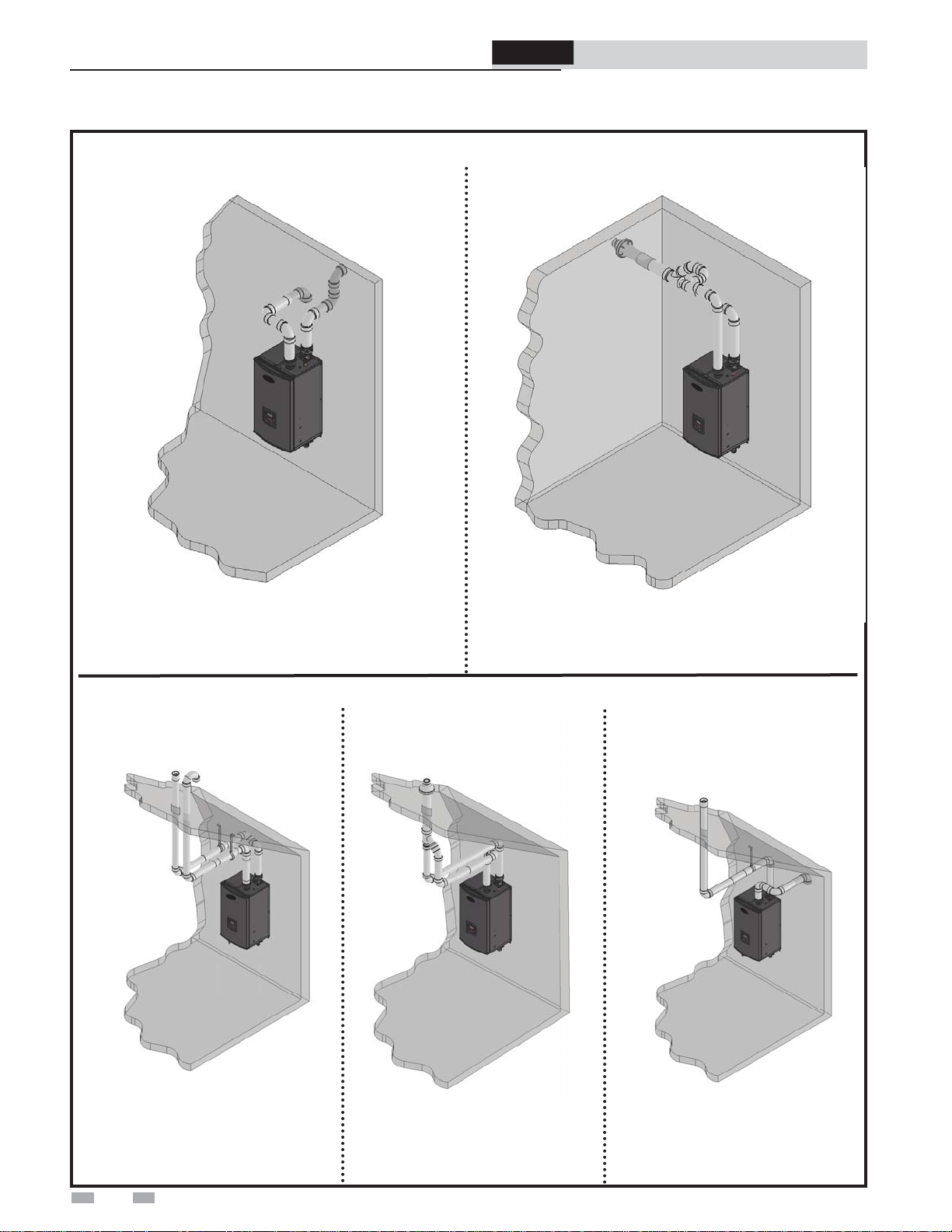
3 General venting
Direct venting options - Sidewall Vent
ProLine® XE
Combi Boiler
Installation & Service Manual
DIR #2000534593 00
Figure 3-1 Two-Pipe Sidewall Termination - See
page 22 for more details
Direct venting options - Vertical Vent
DIR #2000534592 00
Figure 3-2 PVC/CPVC Concentric Sidewall
Termination - See page 25 for more details
DIR #2000534588 00
Figure 3-3 Two-Pipe Vertical
Termination - See page 28 for more
details
14
DIR #2000534590 00
Figure 3-4 PVC/CPVC Concentric
Vertical Termination - See page 30
for more details
DIR #2000534587 00
Figure 3-5 Vertical Vent, Sidewall
Air
Page 15
3 General venting (continued)
Install vent and combustion air piping
ProLine® XE
Combi Boiler
Installation & Service Manual
DANGER
WARNING
WARNING
NOTICE
WARNING
CAUTION
The Combi Boiler must be vented and
supplied with combustion and ventilation
air as described in this section. Ensure the
vent and air piping and the combustion
air supply comply with these instructions
regarding vent system, air system, and
combustion air quality. See also Section 1
of this manual.
Inspect finished vent and air piping
thoroughly to ensure all are airtight and
comply with the instructions provided and
with all requirements of applicable codes.
Failure to provide a properly installed vent
and air system will cause severe personal
injury or death.
This appliance requires a special venting
system. Use only approved PVC, CPVC,
polypropylene or stainless steel pipe and
fittings listed in Tables 3C, 3D, and 3F for
vent pipe, and fittings. Failure to comply
could result in severe personal injury,
death, or substantial property damage.
DO NOT mix components from different
systems. The vent system could fail,
causing leakage of flue products into the
living space. Mixing of venting materials
will void the warranty and certification of
the appliance.
Installation must comply with local
requirements and with the National
Fuel Gas Code, ANSI Z223.1 for U.S.
installations or CSA B149.1 for Canadian
installations.
For closet and alcove installations, CPVC,
polypropylene or stainless steel material
MUST BE used in a closet/alcove structure.
Failure to follow this warning could result
in fire, personal injury, or death.
Improper installation of venting systems
may result in injury or death.
The Combi Boiler vent and air piping can be installed through
the roof or through a sidewall. Follow the procedures in this
manual for the method chosen. Refer to the information
in this manual to determine acceptable vent and air piping
length.
You may use any of the vent/air piping methods covered in
this manual. Do not attempt to install the Combi Boiler using
any other means.
You must also install air piping from outside to the boiler
air intake adapter unless following the Optional Room Air
instructions on page 17 of this manual. The resultant
installation is direct vent (sealed combustion) .
Air intake/vent connections
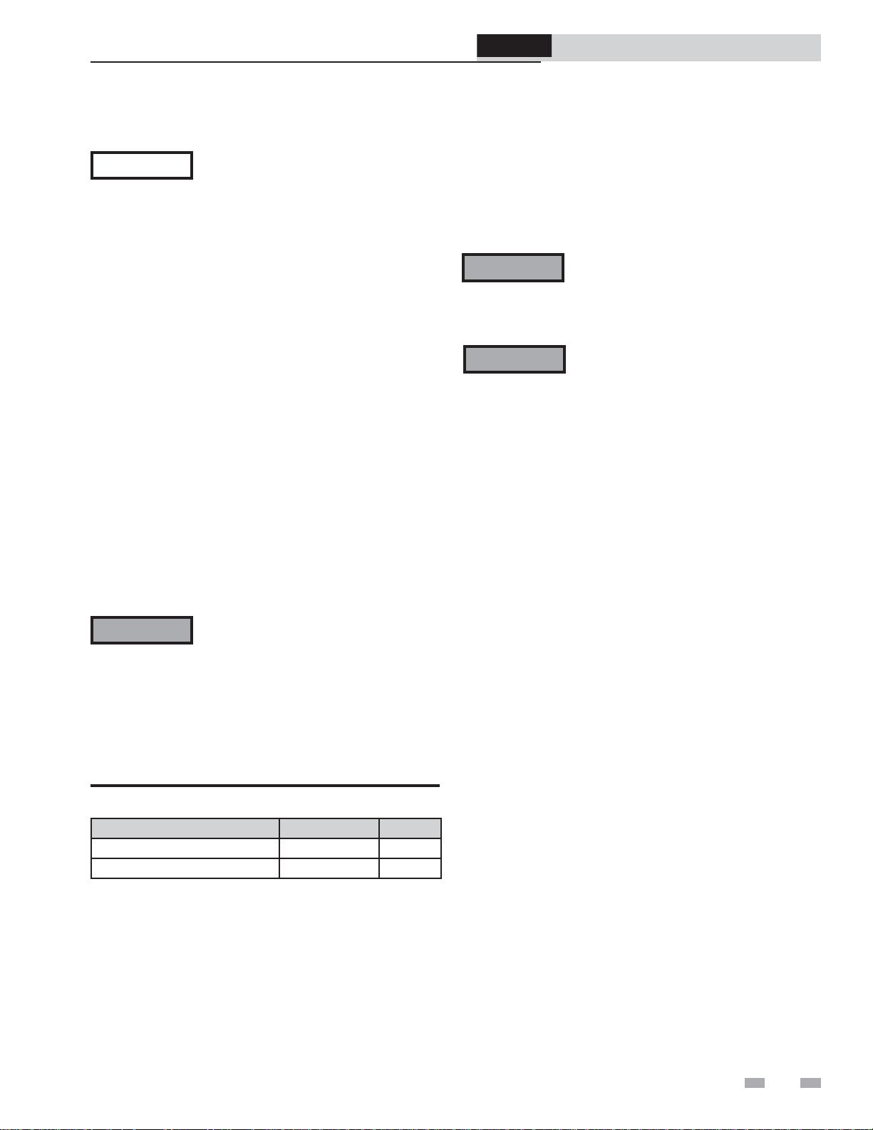
1. Combustion Air Intake Connector (FIG. 3-6)
- Used to provide combustion air directly to the unit from
outdoors. A fitting is provided on the unit for final
connection. Combustion air piping must be supported
per guidelines listed in the National Mechanical Code,
Section 305, Table 305.4 or as local codes dictate.
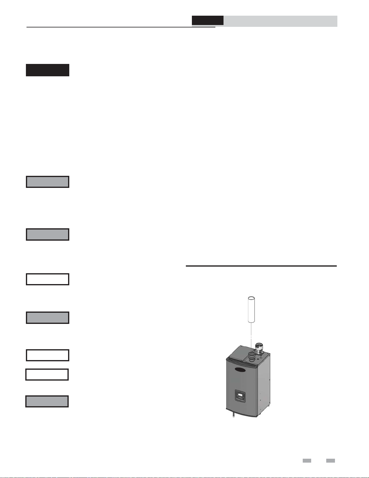
2. Vent Connector (FIG.'s 3-6 thru 3-10) - Used to provide a
passageway for conveying combustion gases to the
outside. A transition fitting is provided on the unit for
final connection. Vent piping must be supported per the
National Building Code, Section 305, Table 305.4 or as
local codes dictate.
Figure 3-6 Near Boiler Air Piping
AIR
NOTICE
WARNING
Follow the instructions in Section 1, page
11 of this manual when removing a boiler
from an existing vent system.
Do not connect any other appliance to the
vent pipe or multiple boilers to a common
vent pipe. Failure to comply could result in
severe personal injury, death, or substantial
property damage.
DIR #2000528317 00
15
Page 16
3 General venting
ProLine® XE
Combi Boiler
Installation & Service Manual
Sizing
The Combi Boiler uses model specific combustion air intake
and vent piping sizes as detailed in Table 3A below.
Table 3A Air Intake/Vent Piping Sizes
Model 2" Max Vent/Air 3" Max Vent/Air
110 100 feet 100 feet
150 60 feet 100 feet
199 N/A 100 feet
NOTICE
Minimum / Maximum allowable combustion
air and vent piping lengths are as follows:
Combustion Air = 7 equivalent feet minimum / 100 equivalent
feet maximum
Vent = 7 equivalent feet minimum / 100 equivalent feet
maximum
When determining equivalent combustion air and vent length,
add 5 feet for each 90° elbow and 3 feet for each 45° elbow.
EXAMPLE: 20 feet of PVC pipe + (4) 90° elbows + (2) 45°
elbows + (1) concentric vent kit (100140480) = 49 equivalent
feet of piping.
NOTICE
Table 3B Concentric Vent Kit Equivalent Vent Lengths
Model
110 - 150 100140485 3 feet 2 inch
110 - 199 100140480 3 feet 3 inch
Increasing or decreasing combustion air
or vent piping sizes is not authorized.
The appliance output rating will reduce by
up to 1.5% for each 25 feet of vent length.
Kit
Number
Equivalent Vent
Length
Vent
Size
Materials
Air inlet pipe materials:
The air inlet pipe(s) must be sealed. Choose acceptable
combustion air inlet pipe materials from the following list:
PVC, CPVC, Polypropylene or ABS
Galvanized steel vent pipe with joints and seams sealed as
specified in this section.
Type “B” double-wall vent with joints and seams sealed as
specified in this section.
AL29-4C, stainless steel material to be sealed to
specification of its manufacturer.
WARNING
NOTICE
Sealing of Type “B” double-wall vent material or galvanized
vent pipe material used for air inlet piping on a sidewall or
vertical rooftop Combustion Air Supply System:
a. Seal all joints and seams of the air inlet pipe using either
Aluminum Foil Duct Tape meeting UL Standard 723 or
181A-P or a high quality UL Listed silicone sealant such as
those manufactured by Dow Corning or General Electric.
b. Do not install seams of vent pipe on the bottom of
horizontal runs.
c. Secure all joints with a minimum of three (3) sheet metal
screws or pop rivets. Apply Aluminum Foil Duct Tape or
silicone sealant to all screws or rivets installed in the vent
pipe.
d. Ensure that the air inlet pipes are properly supported.
The PVC, CPVC, or ABS air inlet pipe should be cleaned and
sealed with the pipe manufacturer’s recommended solvents
and standard commercial pipe cement for the material used.
The PVC, CPVC, ABS, or Flex Duct air inlet pipe should
use a silicone sealant to ensure a proper seal at the appliance
connection and the air inlet cap connection. Dryer vent or
flex duct should use a screw type clamp to seal the vent to
the appliance air inlet and the air inlet cap. Proper sealing of
the air inlet pipe ensures that combustion air will be free of
contaminants and supplied in proper volume.
When a sidewall or vertical rooftop combustion air supply
system is disconnected for any reason, the air inlet pipe
must be resealed to ensure that combustion air will be free of
contaminants and supplied in proper volume.
DANGER
Using air intake materials other than those
specified can result in personal injury,
death or property damage.
The use of double-wall vent or insulated
material for the combustion air inlet pipe is
recommended in cold climates to prevent
the condensation of airborne moisture in
the incoming combustion air.
Failure to properly seal all joints and seams
as required in the air inlet piping may
result in flue gas recirculation, spillage
of flue products and carbon monoxide
emissions causing severe personal injury
or death.
*Plastic pipe may require an adapter (not provided) to
transition between the air inlet connection on the appliance
and the plastic air inlet pipe.
16
Page 17
3 General venting (continued)
Optional room air
NOTICE
Commercial applications utilizing the Combi Boiler may
be installed with a single pipe carrying the flue products to
the outside while using combustion air from the equipment
room. In order to use the room air venting option the
following conditions and considerations must be followed.
• The unit MUST be installed with the appropriate
room air kit (Table 3C).
• The equipment room MUST be provided with
properly sized openings to assure adequate
combustion air. Please refer to instructions provided
with the room air kit.
• There will be a noticeable increase in the noise level
during normal operation from the inlet air opening.
• Using the room air kit makes the unit vulnerable to
combustion air contamination from within the
building. Please review Section 1, Prevent
Combustion Air Contamination, to ensure proper
installation.
• Vent system and terminations must comply with the
standard venting instructions set forth in this
manual.
Optional room air is intended for
commercial applications. Combustion air
piping to the outside is recommended for
residential applications.
ProLine® XE
Combi Boiler
Please read the information given in Table 1A, page 10,
listing contaminants and areas likely to contain them. If
contaminating chemicals will be present near the location of the
boiler combustion air inlet, have your installer pipe the boiler
combustion air and vent to another location, per this manual.
WARNING
WARNING
Installation & Service Manual
If the boiler combustion air inlet is located
in a laundry room or pool facility, for
example, these areas will always contain
hazardous contaminants.
To prevent the potential of severe personal
injury or death, check for areas and products
listed in Table 1A, page 10 before installing
the boiler or air inlet piping.
If contaminants are found, you MUST:
• Remove contaminants permanently.
—OR—
• Relocate air inlet and vent
terminations to other areas.
WARNING
Table 3C Optional Room Air Kit
Air contamination
Pool and laundry products and common household and hobby
products often contain fluorine or chlorine compounds.
When these chemicals pass through the boiler, they can form
strong acids. The acid can eat through the boiler wall, causing
serious damage and presenting a possible threat of flue gas
spillage or boiler water leakage into the building.
When utilizing the single pipe method,
provisions for combustion and ventilation
air must be in accordance with Air for
Combustion and Ventilation, of the
latest edition of the National Fuel Gas
Code, ANSI Z223.1, in Canada, the latest
edition of CGA Standard B149 Installation
Code for Gas Burning Appliances and
Equipment, or applicable provisions of the
local building codes.
Model Kit Number Air Size
110 - 150 100297259 2"
110 - 199 100296893 3"
17
Page 18
3 General venting
PVC/CPVC:
This product has been approved for use with the PVC/CPVC
vent materials listed in Table 3D.
Installing vent and air piping
WARNING
NOTICE
NOTICE
WARNING
WARNING
WARNING
Examples: 1. Seven (7) feet vertical
2. Connector + 90° elbow + 2 feet horizontal
3. One (1) foot vertical + 90° elbow + 1 foot
horizontal
Use only the vent materials, primer, and
cement specified in Table 3D to make the vent
connections. Failure to follow this warning
could result in fire, personal injury, or death.
Use only cleaners, primers, and solvents that
are approved for the materials which are joined
together.
All PVC vent pipes must be glued, properly
supported, and the exhaust must be pitched
a minimum of a 1/4 inch per foot back to the
boiler (to allow drainage of condensate).
Insulation should not be used on PVC or CPVC
venting materials. The use of insulation will
cause increased vent wall temperatures, which
could result in vent pipe failure.
For installations using 2" vent, the first seven
(7) equivalent feet of vent must be CPVC (field
supplied). See examples below.
When transitioning from 2" to 3" vent diameter,
a 2" pipe section and 2" to 3" increaser are
required to be CPVC when PVC/CPVC vent
is used.
ProLine® XE
Combi Boiler
Installation & Service Manual
1. Work from the boiler to vent or air termination. Do
not exceed the lengths given in this manual for the air
or vent piping.
2. Cut pipe to the required lengths and deburr the inside
and outside of the pipe ends.
3. Chamfer outside of each pipe end to ensure even
cement distribution when joining.
4. Clean all pipe ends and fittings using a clean dry rag.
(Moisture will retard curing and dirt or grease will
prevent adhesion.)
5. Dry fit vent or air piping to ensure proper fit up before
assembling any joint. The pipe should go a third to
two-thirds into the fitting to ensure proper sealing after
cement is applied.
6. Priming and Cementing:
a. Handle fittings and pipes carefully to prevent
contamination of surfaces.
b. Apply a liberal even coat of primer to the fitting
socket and to the pipe end to approximately 1/2"
beyond the socket depth.
c. Apply a second primer coat to the fitting socket.
d. While primer is still wet, apply an even coat of
approved cement to the pipe equal to the depth of
the fitting socket along with an even coat of
approved cement to the fitting socket.
e. Apply a second coat of cement to the pipe.
f. While the cement is still wet, insert the pipe into
the fitting, if possible twist the pipe a 1/4 turn as
you insert it. NOTE: If voids are present,
sufficient cement was not applied and joint could
be defective.
g. Wipe excess cement from the joint removing ring
or beads as it will needlessly soften the pipe.
Table 3D PVC/CPVC Vent Pipe and Fittings
Approved PVC/CPVC Vent Pipe and Fittings
Item Material Standard
PVC Schedule 40, 80 ANSI/ASTM D1785
Vent pipe
PVC - DWV ANSI/ASTM D2665
CPVC Schedule 40, 80 ANSI/ASTM F441
PVC Schedule 40 ANSI/ASTM D2466
Vent fittings
PVC Schedule 80 ANSI/ASTM D2467
CPVC Schedule 80 ANSI/ASTM F439
PVC - DWV ANSI/ASTM D2665
Pipe Cement /
Primer
NOTICE: DO NOT USE CELLULAR (FOAM) CORE PIPE
PVC ANSI/ASTM D2564
CPVC ANSI/ASTM F493
NOTE: In Canada, CPVC and PVC vent pipe, ttings and cement/
primer must be ULC-S636 certi ed.
18
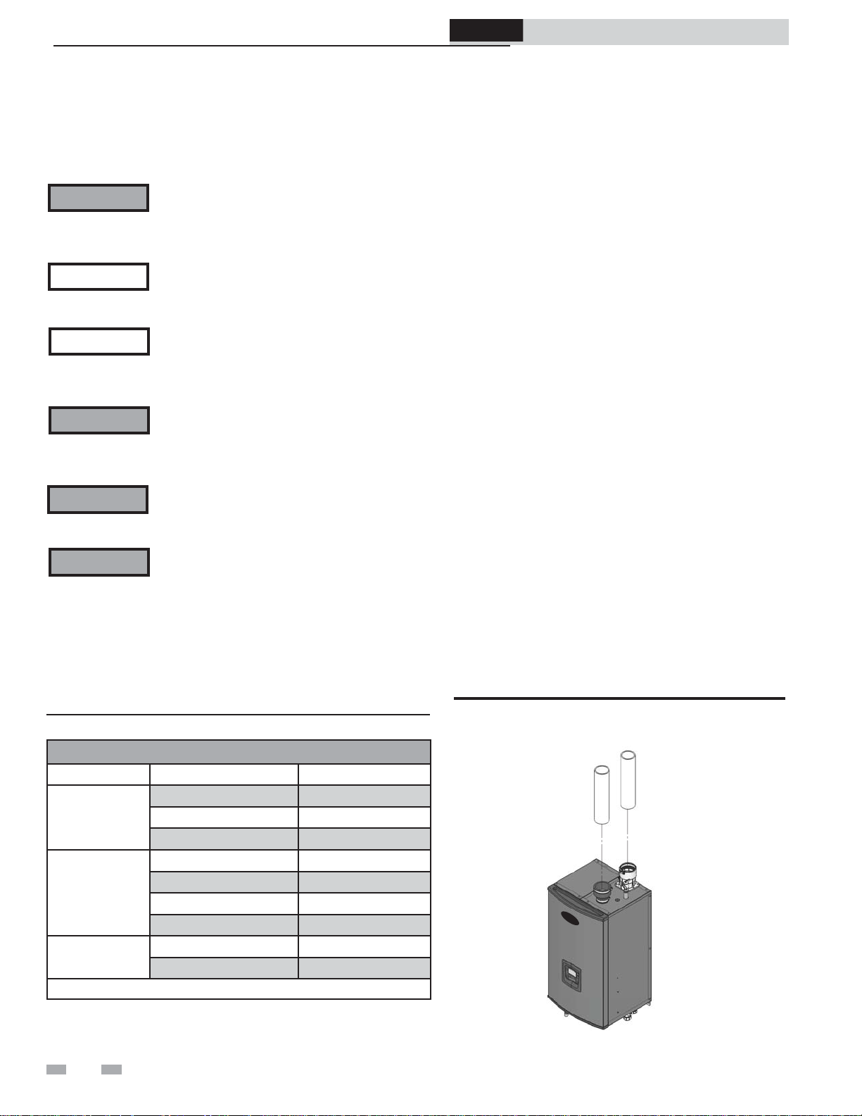
Figure 3-7 Near Boiler PVC/CPVC Venting
VENT
AIR
DIR #2000528318 00
Page 19
3 General venting (continued)
Polypropylene:
This product has been approved for use with polypropylene
vent with the manufacturers listed in Table 3E.
All terminations must comply with listed options in this
manual and be a single-wall vent offering.
For support and special connections required, see the
manufacturer's instructions. All vent is to conform to standard
diameter and equivalent length requirements established.
When determining equivalent combustion air and vent length
for polypropylene single-wall piping:
• 1 foot of Duravent 4 inch single-wall pipe is equivalent
to 1.6 feet of piping
Flexible polypropylene
For use of flex pipe, it is recommended to have the vent material
in 32°F or higher ambient space before bending at installation.
No bends should be made to greater than 45° and ONLY
installed in vertical or near vertical installations (FIG. 3-8).
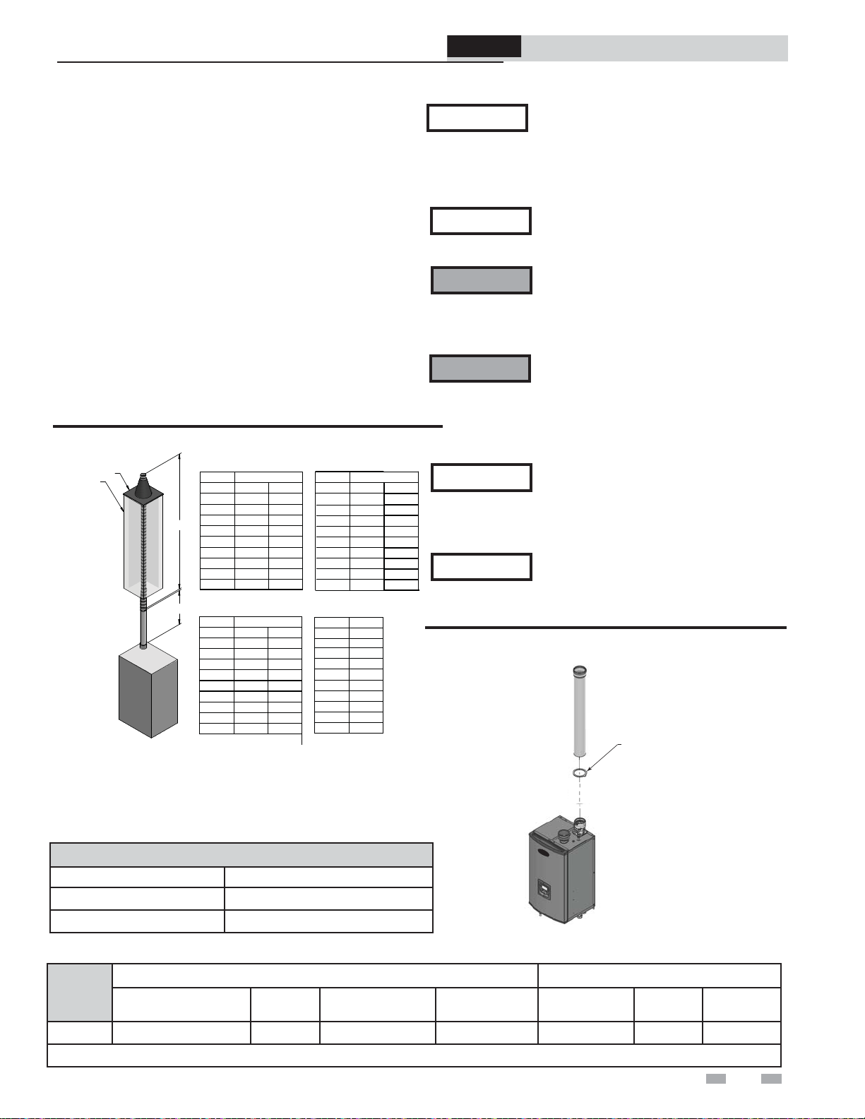
Figure 3-8 Near Boiler Flexible Polypropylene Venting
Duravent 3”
“A” DIM
3” FLEX
3” RIGID
10 FT
20 FT
30 FT
40 FT
50 FT
60 FT
70 FT
80 FT
90 FT
Centrotherm 3”
“A” DIM
3” FLEX
3” RIGID
10 FT
20 FT
30 FT
40 FT
50 FT
60 FT
70 FT
80 FT
90 FT
60 FT
53 FT
47 FT
40 FT
33 FT
27 FT
20 FT
13 FT
7 FT
45 FT
40 FT
35 FT
30 FT
25 FT
20 FT
15 FT
10 FT
5 FT
“B” DIM
4” FLEX
“B” DIM
4” FLEX
90 FT
80 FT
70 FT
60 FT
50 FT
40 FT
30 FT
20 FT
10 FT
90 FT
80 FT
70 FT
60 FT
50 FT
40 FT
30 FT
20 FT
10 FT
CHIMNEY
CAP
B
A
*NOTES: 1) FLEX PIPE MAY ONLY BE RUN IN A VERTICAL ORIENTATION
2) ALL VENT LENGTHS REPRESENTED IN ABOVE CHARTS ARE
EQUIVALENT LENGTHS.
3) SECTION A IS EQUIVALENT FEET OF RIGID PIPE, WHICH MAY
INCLUDE 45 AND 90° ELBOWS. PLEASE SEE SIZING SECTION
FOR DETERMINING EQUIVALENT FEET.
Table 3E Polypropylene Vent Pipe and Fittings
Approved Polypropylene Vent Manufacturers
Make Model
Centrotherm Eco Systems
Duravent (M & G Group)
PolyPro Single-Wall / PolyPro Flex
InnoFlue SW/Flex
Duravent 4”
“A” DIM
4” RIGID
10 FT
20 FT
30 FT
40 FT
50 FT
60 FT
70 FT
80 FT
90 FT
Centrotherm 4”
“A” DIM
4” RIGID
10 FT
20 FT
30 FT
40 FT
50 FT
60 FT
70 FT
80 FT
90 FT
“B” DIM
4” FLEX
30 FT
27 FT
23 FT
20 FT
17 FT
13 FT
10 FT
7 FT
3 FT
“B” DIM
4” FLEX
33 FT
29 FT
26 FT
22 FT
18 FT
15 FT
11 FT
7 FT
4 FT
5” FLEX
90 FT
80 FT
70 FT
60 FT
50 FT
40 FT
30 FT
20 FT
10 FT
IMG00840
ProLine® XE
Combi Boiler
NOTICE
Installation & Service Manual
The installer must use a specific vent
starter adapter at the flue collar connection,
supplied by the vent manufacturer to
adapt to its vent system. See Table 3F for
approved vent adapters. Discard CPVC
starter piece.
NOTICE
All vent connections MUST be secured by
the vent manufacturer's joint connector
(FIG. 3-9).
WARNING
Insulation should not be used on
polypropylene venting materials. The use
of insulation will cause increased vent wall
temperatures, which could result in vent
pipe failure.
WARNING
Use only the adapters and vent system listed
in Tables 3E and 3F. DO NOT mix vent
systems of different types or manufacturers,
unless listed in this manual. Failure to
comply could result in severe personal injury,
death, or substantial property damage.
NOTICE
Installations must comply with applicable
national, state, and local codes. For
Canadian installation, polypropylene vent
must be listed as a ULC-S636 approved
system.
NOTICE
Installation of a polypropylene vent system
should adhere to the vent manufacturer’s
installation instructions supplied with the
vent system.
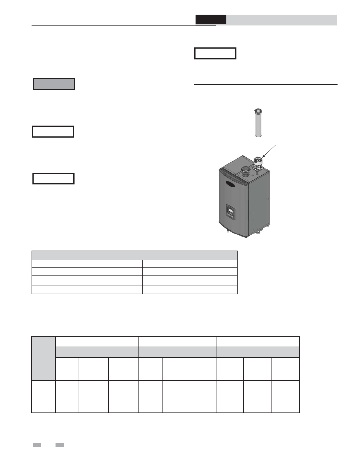
Figure 3-9 Near Boiler Polypropylene Venting Model 199
JOINT CONNECTOR REQUIRED
AT ALL COMPONENT CONNECTIONS
OF VENT SYSTEM
DIR #2000528329 00
Table 3F Approved Polypropylene Terminations and Adapters
Centrotherm InnoFlue SW
Model
110 - 199
* These parts are only needed if the alternate sidewall termination assembly is used.
Polypropylene Adapter/
Flue Clamp
Joint
Connector
Sidewall Retaining
Bracket*
Sidewall Adapter*
ISAG0303 w/IAFC03 IANS03 IATP0303 ISTAGL0303 3PPS-AD 3PPS-LB 3PPS-HLK
Duravent Polypro
Polypropylene
Adapter
Joint
Connector
Sidewall Kit
19
Page 20
3 General venting
ProLine® XE
Combi Boiler
Installation & Service Manual
Stainless steel vent:
This product has been approved for use with stainless steel
using the manufacturers listed in Table 3G.
WARNING
NOTICE
NOTICE
Use only the materials, vent systems, and
terminations listed in Tables 3G and 3H.
DO NOT mix vent systems of different
types or manufacturers. Failure to comply
could result in severe personal injury,
death, or substantial property damage.
The installer must use a specific vent
starter adapter at the flue collar connection,
supplied by the vent manufacturer to
adapt to its vent system. See Table 3H for
approved vent adapters. Discard CPVC
starter piece.
Installations must comply with applicable
national, state, and local codes. Stainless
steel vent systems must be listed as a
UL-1738 approved system for the United
States and a ULC-S636 approved system
for Canada.
NOTICE
Installation of a stainless steel vent system
should adhere to the stainless steel vent
manufacturer’s installation instructions
supplied with the vent system.
Figure 3-10 Near Boiler Stainless Steel Venting
VENT
UNIVERSAL ADAPTER
(FACTORY SUPPLIED)
DIR #2000528338 00
Table 3G Stainless Steel Vent Pipe and Fittings
Approved Stainless Steel Vent Manufacturers
Make Model
Dura Vent (M & G Group) FasNSeal Vent / FasNSeal Flex* Vent
Z-Flex (Nova Flex Group) Z-Vent
Heat Fab (Selkirk Corporation) Saf-T Vent
*Use of FasNSeal Flex smooth inner wall vent is to be used in vertical or near vertical sections only, taking precaution to ensure
no sagging occurs of the vent system. Connect to the FasNSeal rigid vent using specially designed adapters and sealing method,
see manufacturer’s instructions.
Table 3H Approved Stainless Steel Terminations and Adapters
ProTech Heat Fab Z Flex
FasNSeal Saf-T Vent Z-Vent
Model
110 - 199
**Boiler
Adapter
300715
(Intake Air)
Flue
Termination
FSBS3
FSRC3(R.C)
Intake
Air
Termination
303889 --
*Boiler
Adapter
Flue
Termination
9392
5300CI
Intake
Air
Termination
9314TERM --
**Boiler
Adapter
Flue
Termination
2SVSTP03
2SVSRCX03
Intake Air
Termination
2SVSTEX0390
*The stainless steel venting option is only available in 3" vent diameters.
20
Page 21
4 Sidewall direct venting
-
ProLine® XE
Combi Boiler
Installation & Service Manual
Vent/air termination – sidewall
WARNING
WARNING
Determine location
Locate the vent/air terminations using the following
guidelines:
1. The total length of piping for vent or air must not exceed
the limits given in the General Venting Section on page
16 of this manual.
2. You must consider the surroundings when terminating
the vent and air:
a. Position the vent termination where vapors will
not damage nearby shrubs, plants or air
conditioning equipment or be objectionable.
b. The flue products will form a noticeable plume as
they condense in cold air. Avoid areas where the
plume could obstruct window views.
c. Prevailing winds could cause freezing of
condensate and water/ice buildup where flue
products impinge on building surfaces or plants.
d. Avoid possibility of accidental contact of flue
products with people or pets.
e. Do not locate the terminations where wind eddies
could affect performance or cause recirculation,
such as inside building corners, near adjacent
buildings or surfaces, window wells, stairwells,
alcoves, courtyards, or other recessed areas.
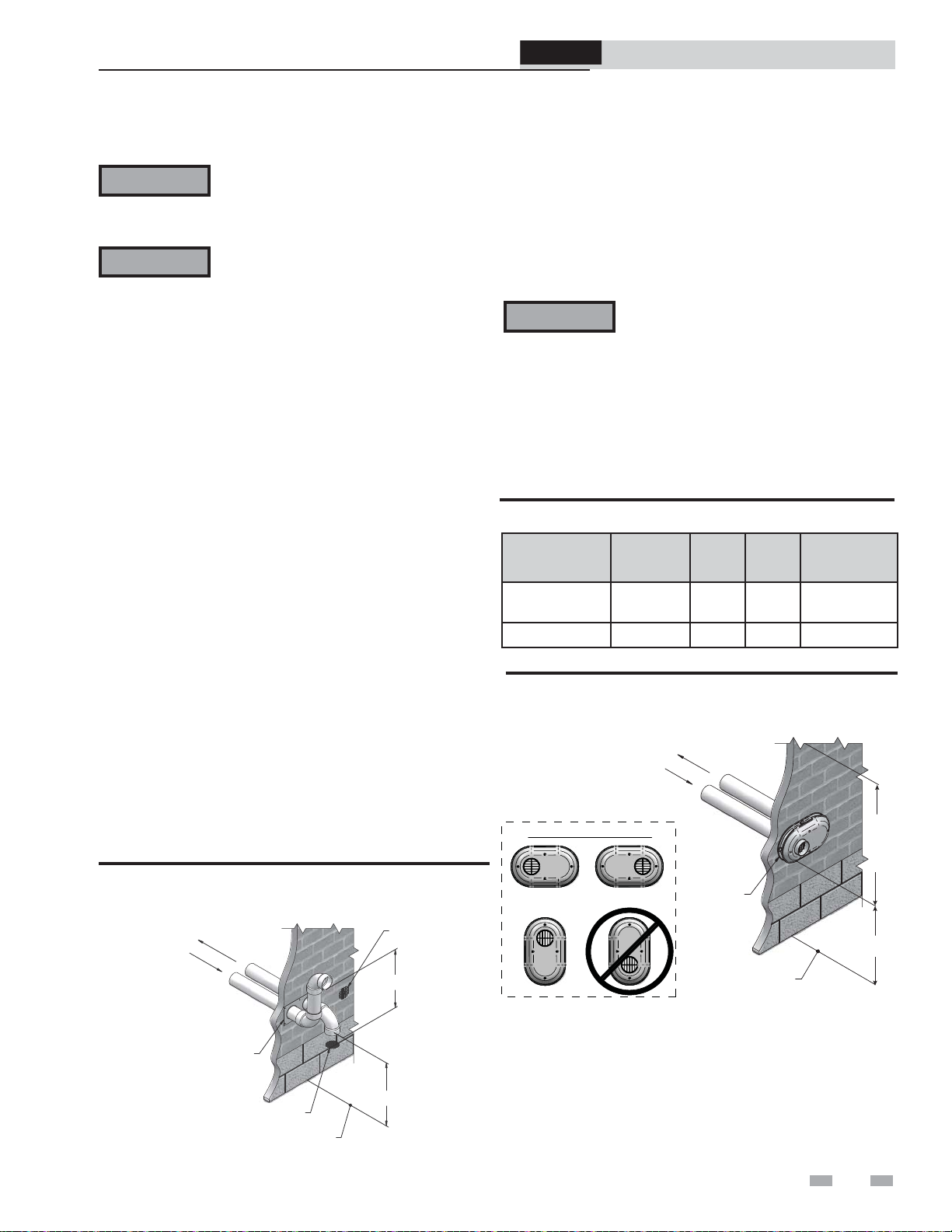
Figure 4-1A PVC/CPVC/Polypropylene Sidewall
Termination of Air and Vent w/Field Supplied Fittings
FROM BOILER
VENT PIPE
CONNECTION
Follow instructions below when
determining vent location to avoid
possibility of severe personal injury, death,
or substantial property damage.
A gas vent extending through an exterior
wall shall not terminate adjacent to a wall
or below building extensions such as eaves,
parapets, balconies, or decks. Failure to
comply could result in severe personal
injury, death, or substantial property
damage.
TO BOILER
INTAKE AIR
CONNECTION
BIRD SCREEN
12” MIN
15” MAX
If using the sidewall termination:
3. The air piping must terminate in a down-turned elbow
as shown in FIG. 4-1A. This arrangement avoids
recirculation of flue products into the combustion air
stream.
4. The vent piping must terminate in an elbow pointed
outward or away from the air inlet, as shown in FIG. 4-1A.
WARNING
Do not exceed the maximum lengths of
the outside vent piping shown in FIG.
4-1A. Excessive length exposed to the
outside could cause freezing of condensate
in the vent pipe, resulting in potential boiler
shutdown.
When venting out a sidewall using PVC, CPVC, or
Polypropylene vent materials, an optional sidewall vent
termination kit can be ordered (reference Table 4A for kit
numbers).
Table 4A Alternate Sidewall Vent Kit
Model
Kit
Number
Air
Size
Vent
Size
Centerline
Width
110 - 150 100297260 2" 2" 5 5/8"
110 - 199 100296897 3" 3" 5 5/8"
Figure 4-1B Alternate PVC/CPVC/ Polypropylene
Sidewall Termination of Air and Vent
TO BOILER
INTAKE AIR
CONNECTION
FROM BOILER
VENT PIPE
CONNECTION
POSSIBLE ORIENTATIONS
VENT / AIR
TERMINATION
GRADE OR
SNOW LINE
12"
MIN
TO
OVER
HANG
12"
MIN
TERMINATION
PLATE
BIRD SCREEN
GRADE OR
SNOW LINE
12”
MIN
21
Page 22
4 Sidewall direct venting
ProLine® XE
Combi Boiler
Installation & Service Manual
Vent/air termination – sidewall
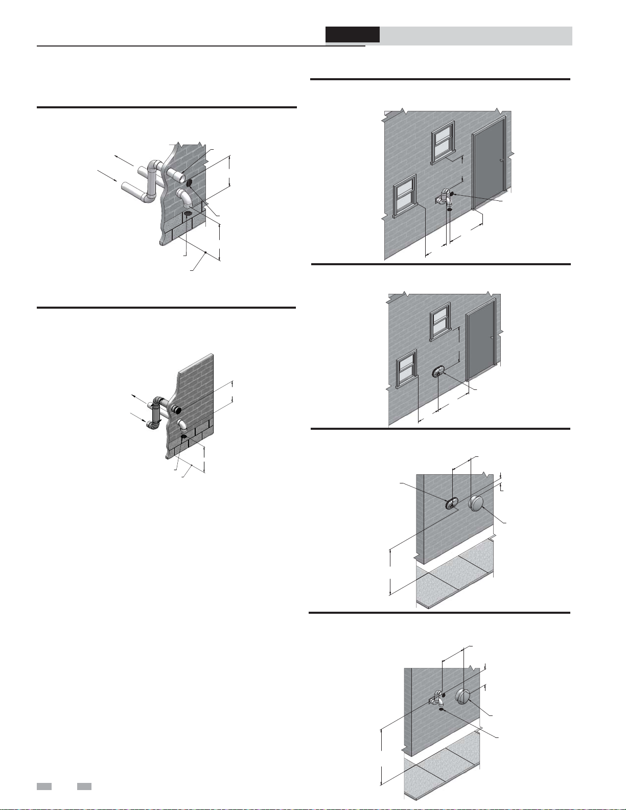
Figure 4-1C Alternate Venting Arrangement (if Space
Allows) w/Field Supplied Fittings
TO BOILER
INTAKE AIR
CONNECTION
FROM BOILER
VENT PIPE
CONNECTION
BIRD
SCREEN
GRADE OR
SNOW LINE
ALTERNATE VENTING ARRANGEMENT
(IF SPACE PERMITS)
Figure 4-1D Alternate Venting Arrangement - Typical
Stainless Steel Sidewall Termination of Air and Vent w/
Field Supplied Fittings
TO BOILER
INTAKE AIR
CONNECTION
FROM
BOILER
VENT PIPE
CONNECTION
BIRD SCREEN
GRADE OR SNOW LINE
5. Maintain clearances as shown in FIG.’s 4-1A thru 4-3B,
pages 21 and 22. Also maintain the following:
a. Vent must terminate:
• At least 6 feet from adjacent walls.
• No closer than 12 inches below roof overhang.
• At least 7 feet above any public walkway.
• At least 3 feet above any forced air intake within
10 feet.
• No closer than 12 inches below or horizontally
from any door or window or any other gravity air
inlet.
b. Air inlet must terminate at least 12 inches above
grade or snow line; at least 12 inches below the vent
termination (FIG. 4-1B); and the vent pipe must not
extend more than 24 inches vertically outside the
building.
c. Do not terminate closer than 4 feet horizontally
from any electric meter, gas meter, regulator, relief
valve, or other equipment. Never terminate above or
below any of these within 4 feet horizontally.
6. Locate terminations so they are not likely to be damaged by
foreign objects, such as stones or balls, or subject to buildup
of leaves or sediment.
12" MIN
COUPLING
12” MIN
15” MAX
BIRD SCREEN
12”
MIN
12" MIN
15" MAX
Figure 4-2A Clearance to Gravity Air Inlets w/Field
Supplied Fittings
12”
MIN
BIRD
SCREEN
(TYPICAL)
12”
MIN
12”
MIN
Figure 4-2B Clearance to Gravity Air Inlets using an
Optional Vent Kit
12"
MIN.
VENT / AIR
TERMINATION
12"
MIN.
12"
MIN.
Figure 4-3A Clearance to Forced Air Inlets using an
Optional Vent Kit
VENT / AIR
TERMINATION
7' MIN. ABOVE ANY
PUBLIC WALKWAY
IF LESS
THAN 10’
36"
MIN.
FORCED AIR
INLET
Figure 4-3B Clearance to Forced Air Inlets w/Field
Supplied Fittings
IF LESS
THAN 10’
36”
MIN
FORCED AIR
INLET
BIRD
SCREEN
7’ MIN ABOVE ANY
PUBLIC WALKWAY
(TYPICAL)
22
Page 23
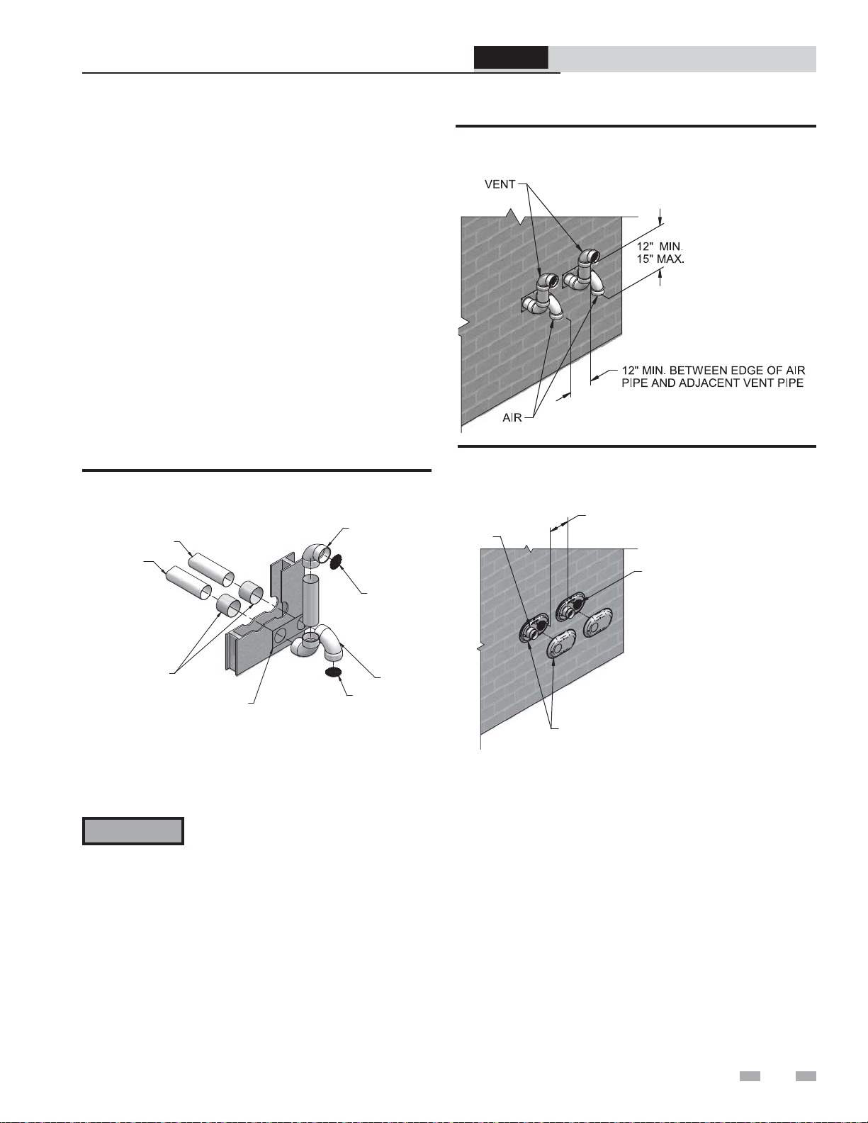
ProLine® XE
Combi Boiler
4 Sidewall direct venting (continued)
Installation & Service Manual
Prepare wall penetrations
1. Air pipe penetration:
a. Cut a hole for the air pipe. Size the air pipe hole as
close as desired to the air pipe outside diameter.
2. Vent pipe penetration:
a. Cut a hole for the vent pipe. For either combustible
or noncombustible construction, size the vent pipe
hole with at least a 1/2 inch clearance around the vent
pipe outer diameter:
• 3½ inch hole for 2 inch vent pipe
• 4½ inch hole for 3 inch vent pipe
b. Insert a galvanized metal thimble in the vent pipe
hole as shown in FIG. 4-4A.
3. Use the sidewall termination plate as a template for
correct location of hole centers.
4. Follow all local codes for isolation of vent pipe when
passing through floors or walls.
5. Seal exterior openings thoroughly with exterior caulk.
Figure 4-4A Sidewall Termination Assembly w/Field
Supplied Fittings
ELBOW
AIR PIPING
VENT PIPING
BIRD SCREEN
Figure 4-5A Multiple Vent Terminations w/Field Supplied
Fittings (must also comply with Figure 4-1A)
Figure 4-5B Alternate Multiple Vent Terminations (must
also comply with Figure 4-1B)
12" MIN. BETWEEN EDGE OF AIR
INLET AND ADJACENT VENT OUTLET
VENT
AIR
GALVANIZED
THIMBLE
SIDEWALL
TERMINATION PLATE
ELBOW
BIRD SCREEN
Multiple vent/air terminations
1. When terminating multiple boilers terminate each vent/
air connection as described in this manual (FIG. 4-5A).
WARNING
2. Place wall penetrations to obtain minimum clearance
of 12 inches between edge of air inlet and adjacent vent
outlet, as shown in FIG. 4-5A for U.S. installations. For
Canadian installations, provide clearances required by
CSA B149.1 Installation Code.
3. The air inlet of a Combi Boiler is part of a direct vent
connection. It is not classified as a forced air intake with
regard to spacing from adjacent boiler vents.
All vent pipes and air inlets must terminate
at the same height to avoid possibility
of severe personal injury, death, or
substantial property damage.
VENT / AIR
TERMINATION
23
Page 24
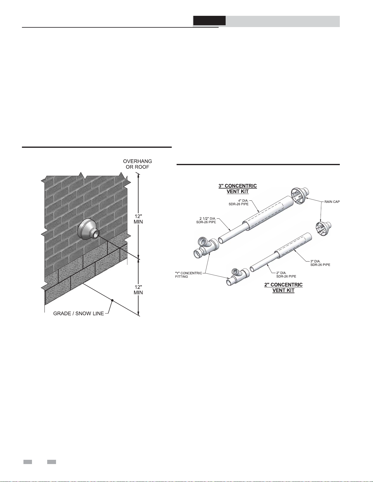
ProLine® XE
Combi Boiler
4 Sidewall direct venting
Sidewall termination – optional concentric vent
Description and usage
The manufacturer offers optional concentric combustion air
and vent pipe termination kits (Factory Kit #100140480 - 3"
or #100140485 - 2"). Both combustion air and vent pipes
must attach to the termination kit. The termination kit must
terminate outside the structure and must be installed as shown
below in FIG. 4-6.
The required combustion vent pipe and fittings are listed in
Table 3B, on page 16 of this manual.
Figure 4-6 Concentric Sidewall Termination
3. Cut one (1) hole (5 inch diameter for #100140480
installations or 4 inch diameter for #100140485 installations)
into the structure to install the termination kit.
4. Partially assemble the concentric vent termination kit.
Clean and cement using the procedures found in these
instructions.
a. Cement the Y concentric fitting to the larger kit pipe
(FIG. 4-7).
b. Cement the rain cap to the smaller diameter kit pipe
(FIG. 4-7).
Figure 4-7 Kit Contents
Installation & Service Manual
Sidewall termination installation
1. Determine the best location for the termination kit (see
FIG. 4-6).
2. Reference the Determine Location Section on page 21 of
this manual for general termination considerations.
24
Page 25
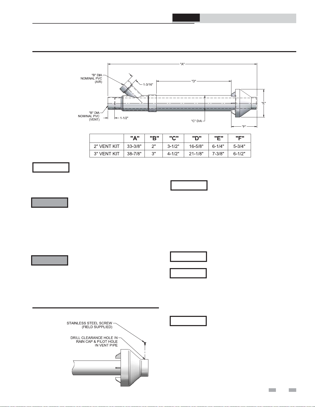
ProLine® XE
Combi Boiler
Installation & Service Manual
4 Sidewall direct venting (continued)
Sidewall termination – optional concentric vent models
Figure 4-8 Concentric Vent Dimensional Drawing
NOTICE
WARNING
WARNING
Figure 4-9 Rain Cap to Vent Pipe Alternate Assembly
Instead of cementing the smaller pipe to
the rain cap, a field-supplied stainless steel
screw may be used to secure the two (2)
components together when field disassembly
is desired for cleaning (see FIG. 4-9).
When using the alternate screw assembly
method, drill a clearance hole in the rain
cap and a pilot hole in the vent pipe for
the screw size being used. Failure to drill
adequate holes may cause cracking of PVC
components, allowing combustion products
to be recirculated. Failure to follow this
warning could result in personal injury or
death.
Do not operate the appliance with the rain
cap removed or recirculation of combustion
products may occur. Water may also collect
inside the larger combustion air pipe and
flow to the burner enclosure. Failure to
follow this warning could result in product
damage or improper operation, personal
injury, or death.
5. Install the Y concentric fitting and pipe assembly through
the structure’s hole.
NOTICE
6. Install the rain cap and small diameter pipe assembly into
the Y concentric fitting and large pipe assembly. Ensure
small diameter pipe is bottomed and cemented in the Y
concentric fitting.
7. Secure the assembly to the structure as shown in FIG.
4-10 using field-supplied metal strapping or equivalent
support material.
NOTICE
NOTICE
NOTICE
Do not allow insulation or other materials
to accumulate inside the pipe assembly
when installing through the hole.
Ensure termination location clearance
dimensions are as shown in FIG. 4-6.
If assembly needs to be extended to
allow sidewall thickness requirement, the
two (2) pipes supplied in the kit may
be replaced by using the same diameter,
field-supplied SDR-26 PVC (D2241) pipe.
Do not extend dimension D more than 60
inches (see FIG. 4-8).
If assembly needs to be reduced, dimension
D can be as short as possible.
25
Page 26
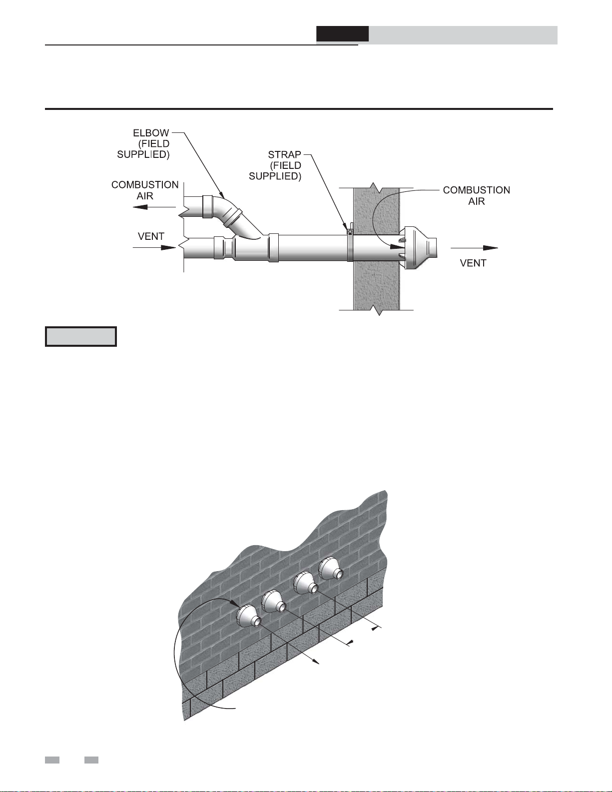
ProLine® XE
Combi Boiler
Installation & Service Manual
4 Sidewall direct venting
Sidewall termination – optional concentric vent
Figure 4-10 Concentric Vent Sidewall Attachment
CAUTION
8. Cement appliance combustion air and vent pipes to the
concentric vent termination assembly. See FIG. 4-10 for
proper pipe attachment.
9. Operate the appliance one (1) heat cycle to ensure
combustion air and vent pipes are properly connected to
the concentric vent termination connections.
DO NOT use field-supplied couplings to
extend pipes. Airflow restriction will occur
and may cause intermittent operation.
Multiventing sidewall terminations
When two (2) or more direct vent appliances are vented near
each other, each appliance must be individually vented (see FIG.
4-11). NEVER common vent or breach vent this appliance.
When two (2) or more direct vent appliances are vented near
each other, two (2) vent terminations may be installed as shown
in FIG. 4-11. It is important that vent terminations be made as
shown to avoid recirculation of flue gases.
26
12"
MINIMUM
VENT
COMBUSTION
AIR
Figure 4-11 Concentric Vent and Combustion Air Termination
Page 27
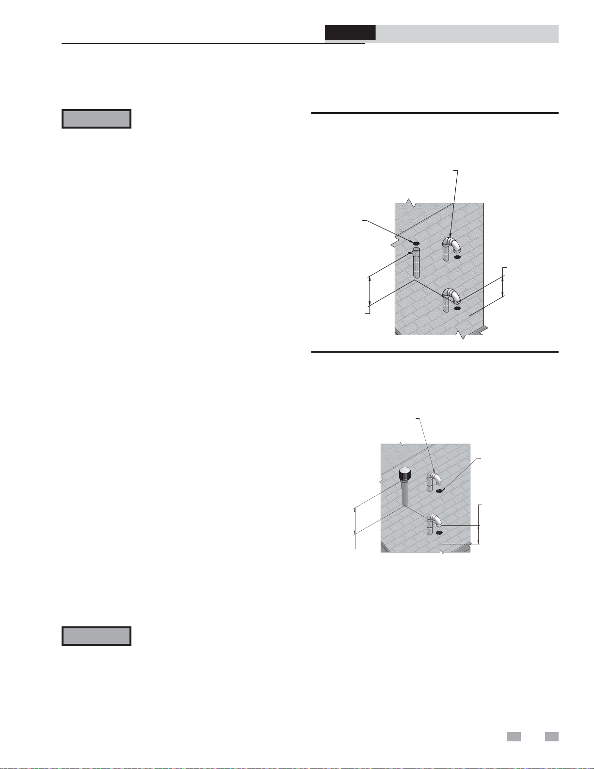
5 Vertical direct venting
/
Vent/air termination – vertical
ProLine® XE
Combi Boiler
Installation & Service Manual
WARNING
Follow instructions below when
determining vent location to avoid
possibility of severe personal injury, death
or substantial property damage.
Determine location
Locate the vent/air terminations using the following
guidelines:
1. The total length of piping for vent or air must not exceed
the limits given in the General Venting Section on page
16 of this manual.
2. Prepare the vent termination and the air termination
elbow (FIG. 5-1A) by inserting bird screens. Bird screens
should be obtained locally.
3. The vent must terminate at least 3 feet above the highest
place in which the vent penetrates the roof and at least
2 feet above any part of a building within 10 horizontal
feet.
4. The air piping must terminate in a down-turned 180°
return pipe no further than 2 feet from the center of the
vent pipe. This placement avoids recirculation of flue
products into the combustion air stream.
5. The vent piping must terminate in an up-turned coupling
as shown in FIG. 5-1A. The top of the coupling must
be at least 1 foot above the air intake. When the vent
termination uses a rain cap as illustrated in FIG. 5-1B
maintain at least 36" (914 mm) above the air inlet. The
air inlet pipe and vent pipe can be located in any desired
position on the roof, but must always be no further than
2 feet (.6 m) apart and with the vent termination at least
1 foot for PVC and 3 feet for stainless steel, above the air
intake.
6. Maintain the required dimensions of the finished
termination piping as shown in FIG. 5-1A.
Figure 5-1A PVC/CPVC/Polypropylene Vertical
Termination of Air and Vent
ALTERNATE INTAKE LOCATIONS:
INTAKE PIPES MAY BE LOCATED
ANYWHERE WITHIN 24” OF VENT
PIPE
BIRD SCREEN
(TYPICAL)
VENT
COUPLING
(FIELD SUPPLIED)
VENT OUTLET
12” MINIMUM
ABOVE AIR INLET
COMBUSTION
AIR
6” MINIMUM
ABOVE ROOF
SNOW LINE
Figure 5-1B Stainless Steel Vertical Termination of Air
and Vent
ALTERNATE INTAKE LOCATIONS:
INTAKE PIPES MAY BE LOCATED
ANYWHERE WITHIN 24” (610 MM)
OF VENT PIPE
BIRD SCREEN
(TYPICAL)
6" (152 MM) MINIMUM
ABOVE ROOF /
SNOW LINE
VENT OUTLET
36” (914 MM) MINIMUM
ABOVE AIR INLET
VENT
COMBUSTION
AIR
7. Do not extend exposed vent pipe outside of building
more than shown in this document. Condensate could
freeze and block vent pipe.
WARNING
Rooftop vent and air inlet terminations
must terminate in the same pressure
zone, unless vertical vent sidewall air is
set up, reference this section, page 28 and
Section 4 - Air Intake Clearances.
8. Locate terminations so they are not likely to be damaged by
foreign objects, such as stones or balls, or subject to buildup
of leaves or sediment.
27
Page 28
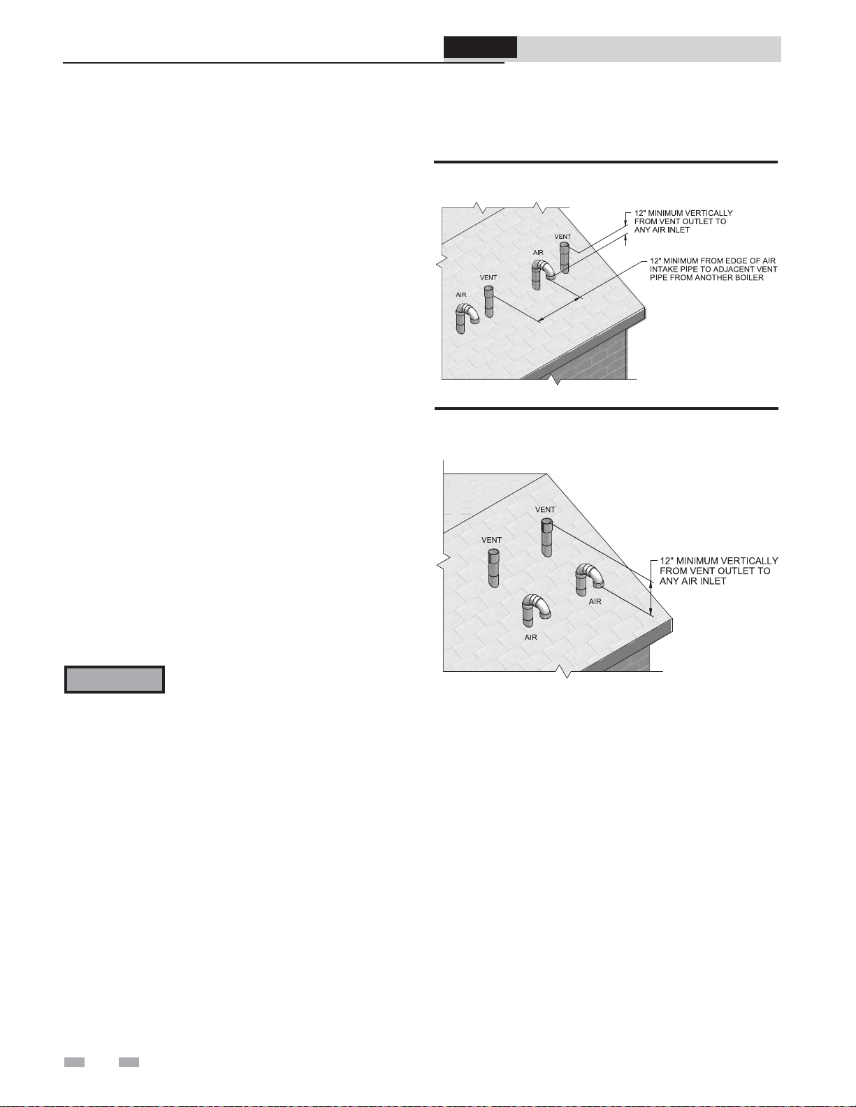
5 Vertical direct venting
Vent/air termination – vertical
ProLine® XE
Combi Boiler
Installation & Service Manual
Prepare roof penetrations
1. Air pipe penetration:
a. Cut a hole for the air pipe. Size the air pipe hole as
close as desired to the air pipe outside diameter.
2. Vent pipe penetration:
a. Cut a hole for the vent pipe. For either combustible
or noncombustible construction, size the vent pipe
hole with at least a 1/2 inch clearance around the
vent pipe outer diameter:
• 4½ inch hole for 3 inch vent pipe
• 5½ inch hole for 4 inch vent pipe
b. Insert a galvanized metal thimble in the vent pipe
hole.
3. Space the air and vent holes to provide the minimum
spacing shown in FIG. 5-1A, page 27.
4. Follow all local codes for isolation of vent pipe when
passing through floors, ceilings, and roofs.
5. Provide flashing and sealing boots sized for the vent pipe
and air pipe.
Figure 5-2 Vertical Terminations with Multiple Boilers
Figure 5-3 Alternate Vertical Terminations with Multiple
Boilers
Multiple vent/air terminations
1. When terminating multiple boilers, terminate each vent/
air connection as described in this manual (FIG. 5-2).
WARNING
2. Place roof penetrations to obtain minimum clearance of
12 inches between edge of air intake elbow and adjacent
vent pipe of another boiler for U.S. installations (see
FIG. 5-2). For Canadian installations, provide clearances
required by CSA B149.1 Installation Code.
3. The air inlet of a Combi Boiler is part of a direct vent
connection. It is not classified as a forced air intake with
regard to spacing from adjacent boiler vents.
Terminate all vent pipes at the same height
and all air pipes at the same height to
avoid possibility of severe personal injury,
death, or substantial property damage.
28
Page 29

ProLine® XE
Combi Boiler
Installation & Service Manual
5 Vertical direct venting (continued)
Vertical termination – optional concentric vent
Description and usage
The manufacturer offers an optional concentric combustion
air and vent pipe termination kit. Both combustion air
and vent pipes must attach to the termination kit. The
termination kit must terminate outside the structure and
must be installed as shown in FIG. 5-4.
Field supplied pipe and fittings are required to complete
the installation.
The required combustion air and vent pipe fittings are
listed in Table 3B, on page 16 of this manual.
Vertical termination installation
1. See Section 5, Vertical Direct Venting - Determine
Location (where applicable).
Figure 5-4 Concentric Vertical Termination
2. Cut one (1) hole (5 inch diameter for #100140480 installations
or 4 inch diameter for #100140485 installations) into the
structure to install the termination kit.
3. Partially assemble the concentric vent termination kit.
Clean and cement following the cleaning procedures in
these instructions.
a. Cement the Y concentric fitting to the larger
diameter kit pipe (see FIG. 4-7, page 24).
b. Cement rain cap to the smaller diameter kit pipe (see
FIG. 4-7, page 24).
NOTICE
WARNING
Instead of cementing the smaller pipe to
the rain cap, a field supplied stainless steel
screw may be used to secure the two (2)
components together when field disassembly
is desired for cleaning (see FIG. 4-9, page
25).
When using the alternate screw assembly
method, drill a clearance hole in the rain
cap and a pilot hole in the vent pipe for
the screw size being used. Failure to drill
adequate holes may cause cracking of PVC
components, allowing combustion products
to be recirculated. Failure to follow this
warning could result in personal injury or
death.
Figure 5-5 Do Not Install U-Bend to Rain Cap
29
Page 30

ProLine® XE
Combi Boiler
Installation & Service Manual
5 Vertical direct venting
Vertical termination – optional concentric vent
WARNING
Do not operate the appliance with
the rain cap removed or recirculation
of combustion products may occur.
Water may also collect inside the larger
combustion air pipe and flow to the
burner enclosure. Failure to follow this
warning could result in product damage
or improper operation, personal injury,
or death.
4. Install the Y concentric fitting pipe assembly through the
structure’s hole and field supplied roof boot/flashing.
NOTICE
Do not allow insulation or other materials
to accumulate inside the pipe assembly
when installing through the hole.
5. Secure the assembly to the roof structure as shown
below in FIG. 5-6 using field supplied metal strapping or
equivalent support material.
Figure 5-6 Concentric Vent Roof Installation
CAUTION
DO NOT use field-supplied couplings to
extend pipes. Airflow restriction will occur.
6. Install the rain cap and the small diameter pipe assembly
into the roof penetration assembly. Ensure the small
diameter pipe is cemented and bottomed in the Y concentric
fitting.
7. Cement the appliance combustion air and vent pipes to
the concentric vent termination assembly. See FIG. 5-6 for
proper pipe attachment.
8. Operate the appliance through one (1) heat cycle to ensure
combustion air and vent pipes are properly connected to
the concentric vent termination connections.
Multiventing vertical terminations
When two (2) or more direct vent appliances are vented near
each other, each appliance must be individually vented (see
FIG. 5-7). NEVER common vent or breach vent this appliance.
When two (2) or more direct vent appliances are vented near
each other, two (2) vent terminations may be installed as shown
in FIG. 5-7. It is important that vent terminations be made as
shown to avoid recirculation of flue gases.
Figure 5-7 Concentric Vent and Combustion Air Vertical
Termination
NOTICE
NOTICE
Ensure termination height is above the
roof surface or anticipated snow level (12
inches in U.S.A. or 18 inches in Canada) as
shown in FIG. 5-4, page 29.
If assembly is too short to meet height
requirement, the two (2) pipes supplied
in the kit may be replaced by using the
same diameter, field supplied SDR-26 PVC
(D2241) pipe. Do not extend dimension
D more than 60 inches (see FIG. 4-8, page
25).
12” (18” FOR CANADA)
MINIMUM CLEARANCE
ABOVE HIGHEST
ANTICIPATED SNOW
LEVEL. MAXIMUM OF
24” ABOVE ROOF.
12”
MINIMUM
COMBUSTION
AIR (TYPICAL)
30
Page 31

A
ProLine® XE
Combi Boiler
5 Vertical direct venting (continued)
Alternate vertical concentric venting
This appliance may be installed with a concentric vent
arrangement where the vent pipe is routed through an
existing unused venting system; or by using the existing
unused venting system as a chase for vent and combustion
air routing.
Figure 5-8 Concentric Vent Example 1
Installation & Service Manual
Concentric Venting Arrangement
The venting is to be vertical through the roof. The annular
space between the O.D. of the vent pipe and the I.D. of the
existing unused venting system is utilized for the combustion
air source.
The minimum size of the existing vent system required to
achieve enough annular space for combustion air can be
found in Table 5A below.
The upper and lower termination as well as any other unsealed
joints in the existing vent system must be sealed to ensure that
all combustion air is drawn from under the vent cap as shown
in FIG.’s 5-8 and 5-9.
Approved venting materials must be used as specified in
Table 3D on page 18.
Follow all vent / air termination and clearance requirements
per this section to the appropriate example. Installation must
comply with local requirements and with the National Fuel
Gas Code.
The maximum allowable equivalent vent and air intake
lengths for this venting arrangement are to be determined
from the General Venting Section.
If an existing unused venting system is converted for use
with this method of concentric venting, the installer must
ensure that the existing venting system is clean and free from
particulate contamination that will harm this appliance and
cause increased nuisance calls or maintenance. See Table 1A
on page 10 for a list of corrosive contaminants and sources.
FLUE EXHAUST
SEAL
AIR INLET
12”
MIN
SEALED
CAP
DIR #2000534607 00
*For concept illustration only. Individual installations may vary
due to job site specific equipment.
COMBUSTION AIR
EXISTING
Figure 5-9 Concentric Vent Example 2
FLUE EXHAUST
SEAL
COMBUSTION AIR
IR INLET
WITH SCREEN
EXISTING
SEAL
SEAL
are shown for illustrative purposes in FIG.’s 5-8 and 5-9.
Two example scenarios of a concentric venting arrangement
SEALED
CAP
Table 5A Alternate Vertical Concentric Vent / Chase Sizes
Model
Vent / Air
Inlet Size
Minimum Existing
Vent / Chase Size
DIR #2000534609 00
110 - 150 2" 4"
110 - 199 3" 5"
*For concept illustration only. Individual installations may vary
due to job site specific equipment.
31
Page 32

A
5 Vertical direct venting
Existing vent as a chase
Follow all existing termination and clearance requirements
and allowable pipe lengths. Use only approved venting
materials listed in the General Venting Section of this manual.
Figure 5-10 Existing Vent as a Chase
FLUE EXHAUST
IR INLET
WITH SCREEN
SEALED
CAP
SEAL
EXISTING
SEAL
ProLine® XE
Combi Boiler
Installation & Service Manual
DIR #2000534613 00
*For concept illustration only. Individual installations
may vary due to job site specific equipment.
32
Page 33

6A Hydronic piping
ProLine® XE
Combi Boiler
Installation & Service Manual
System water piping methods
The Combi Boiler is designed to function in a closed loop
pressurized system not less than 12 psi (Non-metallic system
piping must have an oxygen barrier to be considered a closed
loop). A temperature and pressure gauge is included to
monitor system pressure and outlet temperature and should
be located on the boiler outlet.
Each boiler installation must have an air elimination device,
which will remove air from the system. Install the boiler
so the gas ignition system components are protected from
water (dripping, spraying, etc.) during appliance operation
for basic service of circulator replacement, valves, and others.
Observe a minimum of a 1/4 inch clearance around all
un-insulated hot water pipes when openings around the
pipes are not protected by non-combustible materials.
Low water cutoff device
On a boiler installed above radiation level, some states and
local codes require a low water cutoff device at the time of
installation.
Chilled water system
If the boiler supplies hot water to heating coils in air handler
units, flow control valves or other devices must be installed to
prevent gravity circulation of heater water in the coils during
the cooling cycle. A chilled water medium must be piped in
parallel with the heater.
Freeze protection
Freeze protection for new or existing systems must use
glycol that is specially formulated for this purpose. This
includes inhibitors, which prevent the glycol from attacking
the metallic system components. Make certain to check that
the system fluid is correct for the glycol concentration and
inhibitor level. The system should be tested at least once
a year and as recommended by the producer of the glycol
solution. Allowance should be made for the expansion of the
glycol solution in the system piping.
WARNING
Use only inhibited propylene glycol
solutions, which are specifically formulated
for hydronic systems. Ethylene glycol is
toxic and can attack gaskets and seals used
in hydronic systems.
Heating fluid and Domestic Hot Water
(DHW) piping
The diameter of the heating fluid (hot boiler water) and DHW
piping will depend on the model number and size of the water
heater being installed.
General piping information
IMPORTANT
Basic steps are listed below along with illustrations on the
following pages (FIG.’s 6-2 through 6-5), which will guide you
through the installation of the Combi Boiler.
1. Connect the system return marked “Boiler Inlet”.
2. Connect the system supply marked “Boiler Outlet”.
3. Install purge and balance valve or shutoff valve and drain
on system return to purge air out of each zone.
4. Install a backflow preventer on the cold feed make-up
water line.
5. Install a pressure reducing valve on the cold feed makeup water line, (15 psi nominal). Check temperature and
pressure gauge (shipped separately), which should read a
minimum pressure of 12 psi.
6. Install a system pump if necessary as shown on the piping
diagrams in this section. Make sure the circulator is
properly sized for the system and friction loss.
7. Install an expansion tank on the system supply. Consult the
tank manufacturer’s instruction for specific information
relating to tank installation. Size the expansion tank for the
required system volume and capacity.
8. Install an air elimination device on the system supply.
9. Install a drain valve at the lowest point of the system.
Note: The boiler cannot be drained completely of water
without purging the unit with an air pressure of 15 psi.
10. This appliance is supplied with a relief valve sized in
accordance with ASME Boiler and Pressure Vessel Code,
Section IV (“Heating Boilers”). Pipe the discharge of the
safety relief valve to prevent injury in the event of pressure
relief. Pipe the discharge to a drain. Provide piping that is
the same size as the safety relief valve outlet. Never block
the outlet of the safety relief valve.
11. Install a field supplied strainer to prevent damage to the
heat exchanger caused by debris entering from the system
piping. When installing in a pre-existing system, a strainer/
filter capable of removing debris left in the system is
recommended.
See the *piping illustrations included in this section, FIG.’s 6-2
through 6-5 for suggested guidelines in piping the Combi Boiler
with either zone valves or circulator pumps.
NOTICE
All boiler piping must contain an oxygen
barrier. This will help prevent any excess
oxygen from entering the system.
*Please note that these illustrations are
meant to show system piping concept only,
the installer is responsible for all equipment
and detailing required by local codes.
33
Page 34

6A Hydronic piping
ProLine® XE
Combi Boiler
Installation & Service Manual
Near boiler piping components
1. Boiler system piping:
Boiler system piping MUST be sized per the pipe
requirements listed in Table 6A. Reducing the pipe size
can restrict the flow rate through the boiler, causing
inadvertent high limit shutdowns and poor system
performance.
2. Boiler circulating pump:
Factory supplied. System piping must be sized to meet the
minimum requirements in Table 6A on page 35.
3. Boiler isolation valves:
Field supplied. Full port ball valves are required. Failure
to use full port ball valves could result in a restricted flow
rate through the boiler.
4. Check valves:
Field supplied. Check valves are recommended for
installation as shown in FIG.’s 6-2 through 6-5. Failure
to install check valves could result in a reverse flow
condition during pump(s) off cycle.
5. Unions:
Field supplied. Recommended for unit serviceability.
6. Temperature and pressure gauge:
Factory supplied. The temperature and pressure gauge is
shipped loose. It is the responsibility of the contractor to
install the temperature and pressure gauge on the boiler
water outlet.
7. Pressure relief valve:
Factory supplied. The pressure relief valve is sized to
ASME specifications. Install the 3/4" NPT fitting on the
top right side of the boiler (images in this manual show
relief valve installed).
WARNING
10. Water Meter:
Field supplied. A water meter to monitor makeup
water is recommended. Makeup water volume should
not exceed 5% of total system per year.
11. Y-Strainer:
Field supplied. Install a Y-strainer or equivalent
multi-purpose strainer just before the boiler pump
at the inlet of the heat exchanger. This item is used to
remove system debris from older hydronic systems
and to protect newer systems.
The National Standard Plumbing
Code, the National Plumbing Code of
Canada and the Uniform Plumbing
Code limit the pressure of the heat
transfer fluid to less than the minimum
working pressure of the potable water
system up to 30 psi maximum. Also,
the heat transfer fluid must be water
or other non-toxic fluid having a
toxicity of Class 1, as listed in Clinical
Toxicology of Commercial Products,
th
5
Edition.
8. Boiler purge valve:
Field supplied. The boiler purge valve is used to
remove entrapped air from the heat exchanger during
start-up.
9. System temperature sensor (optional):
Factory supplied with the unit. The manufacturer offers
a system temperature sensor (100296899). The sensor is to
be installed in the heating loop downstream from the
boiler hot water piping and heating loop junction.
Typically the sensor will be located far enough downstream
to sense system diluted water temperature.
34
Page 35

6A Hydronic piping (continued)
Figure 6-1 Pressure Drop vs. Flow
ProLine® XE
Combi Boiler
Installation & Service Manual
Table 6A Temperature Rise Applications
110
Delta T GPM FT/HD Eq Ft of 1" Pipe
19.1°F 10.6 4.0 53
20°F 10.1 6.0 85
25°F 8.1 13.4 287
30°F 6.7 17.4 523
35°F 5.8 19.9 789
40°F 5.1 21.4 1085
45°F 4.5 22.5 1410
199
Delta T GPM FT/HD Eq Ft of 1" Pipe
34.7°F 10.6 4.0 53
40°F 9.2 9.6 162
45°F 8.2 13.1 277
150
Delta T GPM FT/HD Eq Ft of 1" Pipe
26.0°F 10.6 4.0 53
30°F 9.2 9.6 162
35°F 7.9 14.1 317
40°F 6.9 17.0 490
45°F 6.1 19.0 679
Assumed Equivalent Lengths (1" Pipe)
Fitting / Component Eq Ft
90° Elbow 2.5
45° Elbow 1.0
Tee (straight run) 0.5
Tee (side port) 4.5
Ball Valve 4.3
Swing Check 4.5
Flow Check Valve (typical) 54.0
Y-Strainer 4.5
NOTICE
NOTICE
NOTICE
All equivalent pipe lengths are based on the minimum pipe size of one inch.
The data provided takes into account the boiler and integral pump. Flow determination is based solely on
piping external to the boiler.
In Primary/Secondary, only the boiler loop is considered when determining flow. In full flow applications, all
piping and equipment must be considered.
35
Page 36

6A Hydronic piping
Figure 6-2 Single Boiler - Primary / Secondary Piping
PRESSURE
REDUCING VALVE
PRESSURE
GAUGE
WATER
METER
BACKFLOW
PREVENTER
ProLine® XE
Combi Boiler
Installation & Service Manual
MAKE UP WATER
SYSTEM SUPPLY
TO
SYSTEM
BALL VALVE
(TYPICAL)
BOILER
SENSOR
(OPTIONAL)
SYSTEM
CIRCULATOR
EXPANSION
TANK
DRAIN POINT
(TYPICAL)
AIR
SEPARATOR
MAY SUBSTITUTE LOW LOSS HEADER
FROM
SYSTEM
NOT TO EXCEED 4 PIPE DIA OR MAX. OF 12" APART
Y-STRAINER
CHECK
VALVE
NOTICE
NOTICE
36
UNION
(TYPICAL)
TEMPERATURE /
PRESSURE
GAUGE
DRAIN
DIR #2000529680
DHW piping omitted for clarity.
Please note that these illustrations are meant to show system piping concept only, the installer is responsible
for all equipment and detailing required by local codes.
Page 37

6A Hydronic piping (continued)
Figure 6-3 Single Temperature Zoned with Circulators
ProLine® XE
Combi Boiler
ZONE #1
Installation & Service Manual
BOILER
WATER
METER
MAKE UP WATER
PRESSURE
REDUCING VALVE
BACKFLOW
PREVENTER
AIR SEPARATOR
BALL VALVE
(TYPICAL)
DRAIN POINT
(TYPICAL)
PRESSURE
GAUGE
SYSTEM SUPPLY
SENSOR
(WHEN USED)
ZONE #2
EXPANSION
TANK
MAY SUBSTITUTE LOW LOSS HEADER
Y-STRAINER
CHECK
VALVE
ZONE #3
ZONE #4
FLOW CHECK
VALVE
(TYPICAL)
ZONE CIRCULATORS
(TYPICAL)
NOTICE
NOTICE
TEMPERATURE /
PRESSURE
GAUGE
UNION
(TYPICAL)
DIR #2000533824
DRAIN
DHW piping omitted for clarity.
Please note that these illustrations are meant to show system piping concept only, the installer is responsible
for all equipment and detailing required by local codes.
37
Page 38

ProLine® XE
Combi Boiler
6A Hydronic piping
Figure 6-4 Multiple Boilers - Single Temperature Zoned with Circulators
Model
110 1" 1-1/4" 1-1/4" 1-1/2" 2" 2" 2"
150 1-1/2" 2" 2" 2-1/2" 2-1/2" 3" 3"
199 2" 2" 2-1/2" 2-1/2" 3" 3" 3-1/2"
2345678
ZONE #1
Installation & Service Manual
Number of Units
Required Pipe Sizes
BOILER 2
REDUCING VALVE
BACKFLOW
PREVENTER
WATER
METER
MAKE UP
WATER
AIR SEPARATOR
BALL VALVE
(TYPICAL)
PRESSURE
SYSTEM SUPPLY
SENSOR
(OPTIONAL)
DRAIN POINT
(TYPICAL)
BOILER 1
TEMPERATURE /
PRESSURE GAUGE
EXPANSION
TANK
ZONE #2 ZONE #3 ZONE #4
FLOW CHECK
(TYPICAL)
ZONE CIRCULATORS
MAY SUBSTITUTE LOW LOSS HEADER
NOT TO EXCEED 4 PIPE DI A OR MAX. OF 12" APART
Y-STRAINER
(TYPICAL)
NOTICE:
CASCADE IS FOR
SPACE HEAT ONLY.
VALVE
(TYPICAL)
CAUTION
NOTICE
38
TEMPERATURE /
PRESSURE GAUGE
UNION
(TYPICAL)
DIR #2000529699
Mixing valves are required for the protection of low temperature loops.
Please note that these illustrations are meant to show system piping concept only, the installer is responsible
for all equipment and detailing required by local codes.
Page 39

6A Hydronic piping (continued)
Figure 6-5 Single Temperature Piped with Air Handler
ProLine® XE
Combi Boiler
Installation & Service Manual
BOILER
REDUCING VALVE
BACKFLOW
PREVENTER
WATER
METER
MAKE UP WATER
AIR SEPARATOR
BALL VALVE
(TYPICAL)
DRAIN POINT
PRESSURE
(TYPICAL)
PRESSURE
GAUGE
EXPANSION
TANK
Y-STRAINER
SYSTEM SUPPLY
SENSOR
(OPTIONAL)
AIR
HANDLER
NOTICE
NOTICE
TEMPERATURE /
PRESSURE
GAUGE
DIR #2000530076 00
UNION
(TYPICAL)
DHW piping omitted for clarity.
Please note that these illustrations are meant to show system piping concept only, the installer is
responsible for all equipment and detailing required by local codes.
39
Page 40

6B Domestic water piping
ProLine® XE
Combi Boiler
Installation & Service Manual
Scalding
This combi heater can deliver scalding temperature water
at any faucet in the system. Be careful whenever using hot
water to avoid scalding injury. Certain appliances such as
dishwashers and automatic clothes washers may require
increased temperature water. By setting the thermostat
on this combi heater to obtain the increased temperature
water required by these appliances, you may create the
potential for scald injury. To protect against injury, you
MUST install an ASSE 1070 anti-scald mixing valve in the
water system. This valve will reduce point of discharge
temperature by mixing cold and hot water in branch
supply lines. Such valves are available from the local
plumbing supplier.
WARNING
An ASSE 1070 anti-scald mixing
valve is REQUIRED. Failure to
comply could result in property
damage, severe injury, or death.
Water chemistry
Any damage or failure resulting from improper water
chemistry, or heating anything other than potable water.
DEFINITION OF POTABLE WATER - Potable water
is defined as drinkable water supplied from utility or
well water in compliance with EPA secondary maximum
contaminant levels (40 CFR Part 143.3) as shown in Table
6C - Potable Water.
Table 6C Potable Water
Potable Water Levels
Contaminant Level
Aluminum 0.05 to 0.2 mg/l
Chloride 250 mg/l
Color 15 color units
Copper 1.0 mg/l
Corrosivity Non-corrosive
Fluoride 2.0 mg/l
Foaming Agents 0.5 mg/l
Iron 0.3 mg/l
Manganese 0.05 mg/l
Odor 3 threshold odor number
pH 6.5 - 8.5
Silver 0.1 mg/l
Sulfate 250 mg/l
Total Dissolved Solids (TDS) 500 mg/l
Zinc 5 mg/l
The following table (Table 6B) details the relationship of
water temperature and time with regard to scald injury
and may be used as a guide in determining the safest water
temperature for your applications.
Table 6B Approximate Time / Temperature Scald Chart
APPROXIMATE TIME / TEMPERATURE
RELATIONSHIPS IN SCALDS
120°F More than 5 minutes
125°F 1 1/2 to 2 minutes
130°F About 30 seconds
135°F About 10 seconds
140°F Less than 5 seconds
145°F Less than 3 seconds
150°F About 1 1/2 seconds
155°F About 1 second
40
Near heater piping components
1. Recirculation pump (optional):
Field supplied. The recirculation pump shuts off flow
at the desired DHW set point.
2. Check valves:
Field supplied. Check valves are recommended for
installation as shown in FIG.’s 6-6 through 6-8. Failure
to install check valves could result in a reverse flow
condition during pump(s) off cycle.
3. Domestic hot water isolation valves:
Field supplied. Full port ball valves are
required. Failure to use full port ball valves could
result in a restricted flow rate through the boiler.
4. Anti-scald mixing valve:
Field supplied. For use when utilizing the DHW option.
An ASSE 1070 anti-scald mixing valve is required.
5. Unions:
Field supplied. Recommended for unit serviceability.
6. Temperature and pressure gauge:
Field supplied. It is the responsibility of the contractor
to provide and install the temperature and pressure
gauge on the boiler water outlet.
7. Pressure relief valve:
Field supplied. The pressure relief valve is sized to
ASME specifications.
Page 41

ProLine® XE
Combi Boiler
Installation & Service Manual
6B Domestic water piping (continued)
Figure 6-6 Combi DHW Piping
BOILER
EXPANSION
TANK
PRESSURE
RELIEF VALVE
(REQUIRED,
FIELD SUPPLIED)
ASSE 1070
ANTI-SCALD
MIXING VALVE
(REQUIRED)
UNION
(TYPICAL)
TEMPERATURE /
PRESSURE GUAGE
HOT
WATER
SUPPLY
HC
M
FLOW
CHECK
COLD
WATER
SUPPLY
NOTICE
NOTICE
WARNING
DIR #2000534676 00
Hydronic piping omitted for clarity.
Please note that these illustrations are meant to show system piping concept only, the installer is
responsible for all equipment and detailing required by local codes.
An ASSE 1070 anti-scald mixing valve is REQUIRED. Failure to comply could result in property
damage, severe injury, or death.
41
Page 42

6B Domestic water piping
A
Figure 6-7 DHW Recirculation w/Dedicated Return
BOILER
Note: Aquastat for DHW
recirculation pump or thermostatic
shut off valve must be used to
stop recirculation water fl ow once
the desired temperature has been
reached.
ProLine® XE
Combi Boiler
Installation & Service Manual
For best performance, Pre-Heat
Mode should be enabled when
using DHW recirculation.
(TYPICAL)
PRESSURE
RELIEF VALVE
(REQUIRED,
FIELD SUPPLIED)
ASSE 1070
ANTI-SCALD
MIXING VALVE
(REQUIRED)
TEMPERATURE /
PRESSURE GAUGE
HOT WATER
FIXTURES
QUASTAT
UNION
FLOW
CONTROL
VALVE
HC
M
EXPANSION
TANK
FLOW
CHECK
WATER
METER
COLD
WATER
SUPPLY
RECIRCULATION
NOTICE
WARNING
PUMP
Hydronic piping omitted for clarity.
To prevent scalding from DHW recirculation temperature creep, a suitable method to stop recirculation
flow once water in the loop has reached the desired temperature must be used. Failure to stop water
DIR #2000534677 00
flow once the desired DHW temperature has been reached can result in serious injury or death due to
NOTICE
WARNING
scalding.
Please note that these illustrations are meant to show system piping concept only, the installer is
responsible for all equipment and detailing required by local codes.
An ASSE 1070 anti-scald mixing valve is REQUIRED. Failure to comply could result in property
damage, severe injury, or death.
42
Page 43

ProLine® XE
Combi Boiler
6B Domestic water piping (continued)
Figure 6-8 DHW Piping w/Recirculation Return Through Cold Line
BOILER
Note: Aquastat for DHW
recirculation pump or thermostatic
shut off valve must be used to
stop recirculation water fl ow once
the desired temperature has been
reached.
For best performance, Pre-Heat
Mode should be enabled when
using DHW recirculation.
UNION
(TYPICAL)
Installation & Service Manual
EXPANSION
TANK
COLD
WATER
SUPPLY
RECIRCULATION
WATER
METER
FIELD SUPPLIED)
AQUASTAT
PUMP
PRESSURE
RELIEF VALVE
(REQUIRED,
HOT WATER
FIXTURES
ASSE 1070
ANTI-SCALD
MIXING VALVE
(REQUIRED)
TEMPERATURE /
PRESSURE GAUGE
FLOW
CONTROL
VALVE
HOT
WATER
SUPPLY
HC
M
DIR #2000534675 00
FLOW
CHECK
NOTICE
WARNING
NOTICE
WARNING
Hydronic piping omitted for clarity.
To prevent scalding from DHW recirculation temperature creep, a suitable method to stop recirculation
flow once water in the loop has reached the desired temperature must be used. Failure to stop water
flow once the desired DHW temperature has been reached can result in serious injury or death due to
scalding.
Please note that these illustrations are meant to show system piping concept only, the installer is
responsible for all equipment and detailing required by local codes.
An ASSE 1070 anti-scald mixing valve is REQUIRED. Failure to comply could result in property
damage, severe injury, or death.
43
Page 44

7 Gas connections
Connecting gas supply piping
ProLine® XE
Combi Boiler
Installation & Service Manual
1. Remove the front access panel and refer to FIG. 7-1
to pipe gas to the boiler.
a. Install a field supplied sediment trap / drip leg
upstream of the boiler gas controls.
Figure 7-1 Gas Supply Piping
MANUAL SHUTOFF VALVE
UNION
GAS SUPPLY
DRIP LEG
DIR #2000528364 00
2. Support piping with hangers, not by the boiler or its
accessories.
WARNING
The gas valve and blower will not support
the weight of the piping. Do not attempt
to support the weight of the piping with the
boiler or its accessories. Failure to comply
could result in severe personal injury, death,
or substantial property damage.
3. Purge all air from the gas supply piping.
4. Before placing the boiler in operation, check the boiler and
its gas connection for leaks.
a. Close manual main shutoff valve during any
pressure testing at more than 14 inches w.c.
b. Disconnect the boiler and gas valve from the gas
supply piping during any pressure testing greater
than 14 inches w.c.
WARNING
Do not check for gas leaks with an open
flame – use the bubble test. Failure to
use the bubble test or check for gas leaks
can cause severe personal injury, death, or
substantial property damage.
5. Use pipe sealing compound compatible with propane gases.
Apply sparingly only to male threads of the pipe joints so
that pipe dope does not block gas flow.
44
Page 45

7 Gas connections (continued)
ProLine® XE
Combi Boiler
Installation & Service Manual
WARNING
WARNING
WARNING
Failure to apply pipe sealing compound
as detailed in this manual can result
in severe personal injury, death, or
substantial property damage.
Combi Boilers are typically shipped
ready to fire on natural gas. Check boiler
rating plate to determine which fuel the
boiler is set for. If set to natural gas, it
may be converted to LP by installing an
LP venturi (see page 12). In order to
operate on LP gas, an LP venturi MUST
BE installed. Failure to comply could
result in severe personal injury, death, or
substantial property damage.
Use two wrenches when tightening gas
piping at boiler (FIG. 7-2), using one
wrench to prevent the boiler gas line
connection from turning. Failure to
support the boiler gas connection pipe
to prevent it from turning could damage
gas line components.
Natural gas:
Pipe sizing for natural gas
1. Refer to Table 7A for pipe length and diameter. Based on
rated boiler input (divide by 1,000 to obtain cubic feet per
hour).
a. Table 7A is only for natural gas with specific gravity
0.60 inches, with a pressure drop through the gas
piping of 0.3 inches w.c.
b. For additional gas pipe sizing information, refer to
ANSI Z223.1 (or B149.1 for Canadian installations).
Natural gas supply pressure requirements
1. Pressure required at the gas valve inlet pressure port:
• Maximum 14 inches w.c. with no flow (lockup) or with
boiler on.
• Minimum 4 inches w.c. with gas flowing (verify during
boiler startup).
2. Install 100% lockup gas pressure regulator in supply line if
inlet pressure can exceed 14 inches w.c. at any time. Adjust
lockup regulator for 14 inches w.c. maximum.
Figure 7-2 Inlet Pipe with Backup Wrench
USE BACK UP WRENCH
TO PREVENT PIPE FROM
ROTATING
NOTICE
Maximum inlet gas pressure must not
exceed the value specified. Minimum
value listed is for the purposes of input
adjustment.
DIR #2000528388 00
Propane Gas:
WARNING
Pipe sizing for propane gas
1. Contact gas supplier to size pipes, tanks, and 100%
lockup gas pressure regulator.
Propane Supply Pressure Requirements
1. Adjust propane supply regulator provided by the gas
supplier for 14 inches w.c. maximum pressure.
2. Pressure required at gas valve inlet pressure port:
• Maximum 14 inches w.c. with no flow (lockup) or with
boiler on.
• Minimum 8 inches w.c. with gas flowing (verify during
boiler startup).
Combi Boilers are typically shipped ready to
fire on natural gas. Check boiler rating plate
to determine which fuel the boiler is set for.
If set to natural gas, it may be converted to
LP by installing an LP venturi (see page 12).
In order to operate on LP gas, an LP venturi
MUST BE installed. Failure to comply could
result in severe personal injury, death, or
substantial property damage.
WARNING
Ensure that the high gas pressure regulator
is at least 6 - 10 feet upstream of the
appliance.
45
Page 46

7 Gas connections
Table 7A Natural Gas Pipe Size Chart
Capacity of Schedule 40 Metallic Pipe in Cubic Feet of Natural Gas Per Hour
(based on .60 specific gravity, 0.30" w.c. pressure drop)
ProLine® XE
Combi Boiler
Installation & Service Manual
Pipe
Size
(Inches)
1/2 131 90 72 62 55 N/A N/A N/A N/A N/A N/A N/A N/A N/A
3/4 273 188 151 129 114 104 95 89 83 79 70 63 58 N/A
1 514 353 284 243 215 195 179 167 157 148 131 119 109 102
1 1/4 1,060 726 583 499 442 400 368 343 322 304 269 244 224 209
1 1/2 1,580 1,090 873 747 662 600 552 514 482 455 403 366 336 313
2 3,050 2,090 1,680 1,440 1,280 1,160 1,060 989 928 877 777 704 648 602
2 1/2 4,860 3,340 2,680 2,290 2,030 1,840 1,690 1,580 1,480 1,400 1,240 1,120 1,030 960
3 8,580 5,900 4,740 4,050 3,590 3,260 3,000 2,790 2,610 2,470 2,190 1,980 1,820 1,700
4 17,500 12,000 9,660 8,270 7,330 6,640 6,110 5,680 5,330 5,040 4,460 4,050 3,720 3,460
WARNING
10 20 30 40 50 60 70 80 90 100 125 150 175 200
Combi Boilers are typically shipped ready to fire on natural gas. Check boiler rating plate to determine which
fuel the boiler is set for. If set to natural gas, it may be converted to LP by installing an LP venturi (see page
12). In order to operate on LP gas, an LP venturi MUST BE installed. Failure to comply could result in
severe personal injury, death, or substantial property damage.
Check inlet gas supply
NOTICE
WARNING
The gas piping must be sized for the proper flow and length
of pipe, to avoid excessive pressure drop. Both the gas
meter and the gas regulator must be properly sized for the
total gas load.
If you experience a pressure drop greater than 1 inch w.c.,
the meter, regulator, or gas line is undersized or in need of
service. Perform the steps below when checking inlet gas
supply:
1. Shut OFF power at source.
2. Shut off gas supply at the manual gas valve in the gas
piping to the appliance.
CSA or UL listed flexible gas connections
are acceptable, but you must exercise
caution to ensure that the line has
adequate capacity to allow your boiler
to fire at full rate. Consult with local
codes for proper installation or service
procedures.
DO NOT adjust gas valve outlet
pressure. The gas valve is factory-set
for the correct outlet pressure. This
setting is suitable for natural gas and
propane, requiring no field adjustment.
Attempting to alter the gas valve outlet
pressure could result in damage to the
valve, causing potential severe personal
injury, death, or substantial property
damage.
Length of Pipe in Straight Feet
3. Loosen the set screw one (1) full turn from inside the
pressure tap on top of the gas valve. Place the tubing of
the manometer over the tap once the set screw is
loosened as shown in FIG. 7-3.
4. Slowly turn on the gas supply at the field installed
manual gas valve.
5. Turn ON power at source.
6. Press and hold the RIGHT and DOWN buttons
simultaneously for five (5) seconds to place the boiler into
Service Mode. In Service Mode, the boiler will fire at
ignition speed and will then modulate up to full fire.
7. Adjust the temperature set point on the control panel of
the boiler control module to call for heat.
8. Observe the gas supply pressure as the burner fires at
100% of rated input. Percent of burner input will be
displayed on the control panel.
9. Ensure inlet pressure is within specified range.
Minimum and maximum gas supply pressures are
specified in this section of the manual.
10. If gas supply pressure is within normal range and no
adjustments are needed, proceed on to Step 11.
11. If the gas pressure is out of range, contact the gas utility,
gas supplier, qualified installer or service agency to
determine the necessary steps to provide proper gas
pressure to the control.
12. Exit Service Mode.
13. Turn OFF power at source.
46
Page 47

7 Gas connections (continued)
ProLine® XE
Combi Boiler
Installation & Service Manual
14. Shut off the gas supply at the manual gas valve in the gas
piping to the appliance.
15. Remove the manometer from the pressure tap on top of
the gas valve. Re-tighten the set screw inside the pressure
tap.
WARNING
When re-tightening the set screw, be
sure to tighten securely to prevent gas
leaks.
Do not check for gas leaks with an open
flame -- use the bubble test. Failure to
use the bubble test or check for gas leaks
can cause severe personal injury, death,
or substantial property damage.
16. Turn on the gas supply at the manual gas valve.
17. Turn ON power at source.
18. Adjust the temperature set point on the control panel
of the boiler control module to the desired
water temperature so the appliance will call for heat.
19. Check burner performance by cycling the system while
you observe burner response. The burner should
ignite promptly. Flame pattern should be stable. Turn
system off and allow burner to cool, then cycle burner
again to ensure proper ignition and flame
characteristics.
Figure 7-3 Inlet Gas Supply Check
DETAIL A
Gas Pressure
The gas pressure must remain between 4 inches w.c. (natural),
8 inches w.c. (LP) minimum and 14 inches w.c. (natural and LP)
maximum during stand-by (static) mode and while in operating
(dynamic) mode. If an in-line regulator is used, it must be a
minimum of 10 feet from the Combi Boiler. It is very important
that the gas line is properly purged by the gas supplier or utility
company. Failure to properly purge the lines or improper line
sizing, will result in ignition failure.
The problem is especially noticeable in NEW LP installations
and also in empty tank situations. This can also occur when
a utility company shuts off service to an area to provide
maintenance to their lines.
Gas valve replacement
The gas valve MUST NOT be replaced with a conventional gas
valve under any circumstances.
WARNING
WARNING
Failure to follow all precautions could
result in fire, explosion, or death!
DO NOT adjust gas valve outlet pressure.
The gas valve is factory-set for the correct
outlet pressure. This setting is suitable
for natural gas and propane, requiring
no field adjustment. Attempting to
alter the gas valve outlet pressure could
result in damage to the valve, causing
potential severe personal injury, death, or
substantial property damage.
LOOSEN SET SCREW
ONE (1) FULL TURN
THEN PLACE TUBING
A
DIR #2000529636 00
OVER PRESSURE
TAP
47
Page 48

8 Field wiring
NOTICE
WARNING
NOTICE
CAUTION
Figure 8-1 Remove Metal Junction Box Cover
For field wiring on Combi units, reference
the Combi Installation and Service
Manual provided with the unit.
ELECTRICAL SHOCK HAZARD – For
your safety, turn off electrical power supply
before making any electrical connections
to avoid possible electric shock hazard.
Failure to do so can cause severe personal
injury or death.
Wiring must be N.E.C. Class 1.
If original wiring as supplied with boiler
must be replaced, use only type 105°C
wire or equivalent.
Boiler must be electrically grounded as
required by National Electrical Code
ANSI/NFPA 70 – latest edition.
Label all wires prior to disconnection when
servicing controls. Wiring errors can
cause improper and dangerous operation.
ProLine® XE
Combi Boiler
Installation & Service Manual
Installation must comply with:
1. National Electrical Code and any other national, state,
provincial, or local codes, or regulations.
2. In Canada, CSA C22.1 Canadian Electrical Code Part 1,
and any local codes.
Line voltage connections
1. Remove the cover of the metal junction box as shown in
FIG. 8-1.
2. Connect 120 vac power wiring using wire nuts (field
supplied) to the labeled line voltage terminal wires in the
junction box.
3. Provide and install a fused disconnect or service switch
(15 amp recommended) as required by the code.
4. To activate a system pump, wire as shown in FIG. 8-2. If
the motor is larger than 2 amps, you must isolate with a
relay.
Low voltage connections
1. Route all low voltage wires through the holes in the bottom
front right side, just under the control panel, as shown in
FIG. 8-3.
2. Connect low voltage wiring to low voltage connection
board as shown in FIG. 8-4 on page 50 of this manual and
the boiler wiring diagram.
HIGH VOLTAGE
JUNCTION BOX
DIR #2000529321 00
Figure 8-2 Line Voltage Field Wiring Connections
SYSTEM PUMP
(OPTIONAL)
NOTICE
Do not run low voltage wires next to high
voltage wires in the same conduit.
Figure 8-3 Routing Field Wiring
LOW VOLTAGE
CONNECTION
BOARD
48
DIR #2000536085 00
LOW VOLTAGE
WIRING HOLES
DIR #2000529643 00
Page 49

8 Field wiring (continued)
ProLine® XE
Combi Boiler
Installation & Service Manual
Thermostat
1. Connect the room thermostat or end switch (isolated
contact only) to the room thermostat as shown in FIG.
8-4.
2. Install the thermostat on the inside wall, away from
influences of drafts, hot or cold water pipes, lighting
fixtures, televisions, sunlight or fireplaces.
3. Thermostat anticipator (if applicable):
a. If connected directly to boiler, set for 0.1 amps.
b. If connected to relays or other devices, set to match
total electrical power requirements of connected
devices. See device manufacturers’ specifications
and thermostat instructions for details.
Outdoor temperature sensor
In accordance with the United States Energy Policy and
Conservation Act, this boiler is equipped with outdoor air
reset, a feature that saves energy by reducing boiler water
temperature as heating load decreases. To use this feature,
the outdoor air sensor provided with the boiler must be
properly installed.
1. Mount the sensor on an exterior wall, shielded from
direct sunlight or flow of heat or cooling from other
sources.
2. Route sensor wires through a designated wiring hole in
the bottom front right side of the boiler (see FIG. 8-3).
3. Connect outdoor temperature sensor (FIG. 8-4) to the
outdoor sensor terminals on the connection board to
enable outdoor reset operation of the Combi Boiler.
System supply sensor
1. By installing the optional system supply sensor into the
supply of the primary loop, the temperature of the primary
supply can be controlled. The boiler control automatically
detects the presence of this sensor, and controls the boiler
firing rate to maintain the system supply temperature to the
set point.
CAUTION
2. The 100170581 sensor provided with the boiler must be
used for the system sensor.
3. Connect the system supply sensor to these terminals (FIG.
8-4).
Do not install the system supply sensor into
the system return.
Wiring of the cascade
When wiring the boilers for Cascade operation, select one boiler
as the Leader boiler. The remaining boilers will be designated as
Members.
Connect the system supply sensor and outdoor air sensor (if
used) to the Leader boiler. For the Cascade system to work
properly the system supply sensor must be installed. The
location of the system supply sensor should be downstream
of the boiler connections in the main system loop. The system
supply sensor should be wired to the Low Voltage Connection
Board at the terminals marked for the system sensor (see FIG.
8-4). The Leader control will use the water temperature at the
system supply sensor to control the operation of the Cascade.
Auxiliary limit switch
A field supplied auxiliary limit switch can be used for the gas
pressure switch. When installing the auxiliary limit switch,
please follow the kit instructions provided with the switch
and then proceed as follows:
1. If the auxiliary switch is mounted to the exterior of the
boiler, run the wires through a knockout in the bottom
front right side of the boiler. If the auxiliary limit switch
is mounted on the interior of the boiler, route the wires
to the connection board.
2. Once the wires are inside the boiler and near the
connection board, connect the wires to the auxiliary
limit switch terminals.
Air handler contacts
A set of un-powered contacts are available on the low voltage
connection board (FIG. 8-4) that can be used to turn off the
fan on an air handler when the diverter valve is in the DHW
position and therefore not providing hot water to the space
heating system. These contacts are normally open and will
close when the diverter valve is in the space heat position.
49
Page 50

8 Field wiring
Figure 8-4 Low Voltage Field Wiring Connections
CUT OFF
LOW WATER
OUTDOOR SENSOR
SYSTEM SUPPLY SENSOR
(OPTIONAL)
ProLine® XE
Combi Boiler
Installation & Service Manual
AUXILIARY LIMIT
(FIELD SUPPLIED)
(FIELD SUPPLIED)
ROOM THERMOSTAT
50
DIR #2000534741 00
Page 51

9 Condensate disposal
ProLine® XE
Combi Boiler
Installation & Service Manual
Condensate drain
1. This boiler is a high efficiency appliance that produces
condensate.
2. The bottom of the boiler has a 3/4 inch pipe for connection
of a 3/4 inch PVC pipe (FIG. 9-1).
3. Slope condensate tubing down and away from the boiler
into a drain or condensate neutralizing filter. Condensate
from the Combi Boiler will be slightly acidic (typically
with a pH from 3 to 5). Install a neutralizing filter if
required by local codes.
A Neutralizer Kit is available from the factory.
4. Do not expose condensate line to freezing temperatures.
5. Use only plastic tubing or piping as a condensate drain
line (FIG. 9-1).
NOTICE
NOTICE
6. A condensate removal pump is required if the boiler is
below the drain. When installing a condensate pump, select
one approved for use with condensing boilers and furnaces.
The pump should have an overflow switch to prevent
property damage from condensate spillage.
Use materials approved by the authority
having jurisdiction. In the absence of other
authority, PVC and CPVC pipe must comply
with ASTM D1785 or D2845. Cement and
primer must comply with ASME D2564 or
F493. For Canada use CSA or ULC certified
PVC or CPVC pipe, fittings, and cement.
To allow for proper drainage on large
horizontal runs, a second line vent may be
required and tubing size may need to increase
to 1 inch.
The condensate line must remain
unobstructed, allowing free flow of
condensate. If condensate is allowed to
freeze in the line or if the line is obstructed in
any other manner, condensate can exit from
the boiler tee, resulting in potential water
damage to property.
Figure 9-1 Condensate Disposal
51
Page 52

10 Start-up
ProLine® XE
Combi Boiler
Installation & Service Manual
Pre-Commissioning Cleaning
1. Prior to fill and start-up, flush the entire heating system.
2. Clean the entire heating system with an approved precommissioning cleaner (comparable to Sentinel X300
or Fernox F3) in accordance with the manufacturer’s
recommendation to remove debris and prolong the life of
the heat exchanger.
3. Clean all water filtering devices in the system.
4. Flush the cleaning solution out of the entire system and
refill.
Fill water
Check/control fill water chemistry
IMPORTANT
The manufacturer recommends the following for properly
filling your boiler with the appropriate water chemistry for
closed loop boilers. Good fill water quality will help extend
the life of the appliance by reducing the effects of lime scale
buildup and corrosion in closed loop systems.
Hardness between 5 and 12 grains per gallon
1. Consult local water treatment companies for hard water
areas (above 12 grains per gallon hardness).
2. Hardness levels that are above 12 grains/gallon can lead
to lime scale buildup throughout the boiler system. If the
fill water is below 5 grains/gallons, usually due to use of a
water softener, it is recommended to mix in some potable
water at the inlet to increase the hardness of the water to
above 5 grains/gallons.
pH between 6.5 and 8.5
1. pH levels below 6.5 can cause an increase in the rate of
corrosion. pH of 8.5 or higher can potentially cause lime
scale buildup.
Total Dissolved Solids (TDS) less than 350 ppm
1. Total dissolved solids are all minerals, salts, metals, and
charged particles that are dissolved in water.
2. The greater the amounts of TDS present, the higher the
corrosion potential due to increased conductivity in the
water.
Chlorine concentration less than 150 ppm
1. Do not fill boiler or operate with water containing
chlorine in excess of 150 ppm.
2. Filling with fresh drinking water should be acceptable.
Conduct water quality testing prior to
installing the appliance. Various solutions
are available to adjust water quality.
Boiler water
CAUTION
CAUTION
Table 10A Boiler Water Chemistry
Speci cation Range
Dissolved Solids < 2000 ppm
• Monitoring pH, chlorides, TDS, and hardness
levels can prolong the life of the appliance by reducing
lime scale buildup, corrosion, and erosion. Check for
leaks to ensure that fresh water is not entering the
system.
• Continual fresh makeup water will reduce boiler life.
• Mineral buildup in the heat exchanger reduces heat
transfer, overheats the stainless steel heat exchanger,
and causes failure.
• The addition of oxygen carried in by makeup water
can cause internal corrosion in system components.
• Leaks in the boiler or piping must be repaired at
once to prevent excessive makeup water. For this
purpose, it is recommended to install a water meter
to easily check the amount of makeup water entering
the system. Makeup water volume should not exceed
5% of the total system volume per year. NOTE: When
makeup water is added, make sure the chemical
additives are added to maintain the correct level.
• An approved multi-metal corrosion inhibitor
(comparable to Sentinel X100 or Fernox F1) is
recommended at the correct concentration and in the
manner recommended by the manufacturer.
Do not use petroleum based cleaning or
sealing compounds in the boiler system.
Gaskets and seals in the system may be
damaged. This can result in substantial
property damage.
DO NOT use "homemade cures" or "boiler
patent medicines". Serious damage to
boiler, personnel, and/or property may
result.
BOILER WATER CHEMISTRY
pH Level 6.5 to 9.5
Chloride < 150 ppm
Freeze protection
WARNING
Ethylene glycol is toxic, DO NOT use as
your freeze protection. Ethylene glycol has a
sweet aroma which children and pets could
mistake as food and ingest; leading to death.
3. Do not use the boiler to directly heat swimming pool or
spa water.
52
Page 53

10 Start-up (continued)
ProLine® XE
Combi Boiler
Installation & Service Manual
1. Use glycol only if needed for freeze protection.
2. Propylene glycol is the recommended freeze protection.
3. Make sure to flush the boiler system before adding glycol.
4. Determine the freeze protection fluid quantity using
system water content, following the fluid manufacturer's
instructions. Boiler water content is listed on page 6.
Remember to include expansion tank water content.
5. Local codes may require a backflow preventer or actual
disconnect from city water supply.
6. When using freeze protection fluid with automatic fill, it is
suggested to install a water meter to monitor water makeup.
Freeze protection fluid may leak before the water begins to
leak, causing the concentration to drop, which reduces the
freeze protection level.
7. The freeze protection set points may be lowered when
freeze protection fluid is used.
8. Consult the glycol manufacturer for details on the suggested
mix of glycol and water for the desired freeze protection
level and the de-rate effect it will have on the boiler output.
Test / replace freeze protection fluid
1. For systems using freeze protection fluids, follow the fluid
manufacturer's instructions.
2. Freeze protection fluid must be replaced periodically due to
degradation of inhibitors over time.
3. It is recommended to test the glycol concentration annually
and adjust within the desired set points.
Oxygen prevention
CAUTION
Dissolved oxygen can have a negative effect on the boiler
system. Oxygen can cause iron oxide to generate iron
deposits. Oxygen may also increase the rate of corrosion
on non-stainless steel parts of the system. A low pH level
combined with oxygen further enhances its corrosive effects.
After boiler installation, check for air leaks in the following
areas:
• Suction gasket
• Pump
• Air valve
• O-ring gaskets
Eliminate all system leaks. Continual
fresh makeup water will reduce boiler
life. Minerals can build up in the
heat exchanger, reducing heat transfer,
overheating the heat exchanger, and
causing heat exchanger failure.
Fill and test water system
1. Fill system only after ensuring the water meets the
requirements of this manual.
2. Close automatic and manual air vents and boiler drain
valve.
3. Fill to correct system pressure. Correct pressure will vary
with each application.
a. The minimum cold water fill pressure for a system is
12 psi.
b. Pressure will rise when the boiler is turned ON and
system water temperature increases.
4. At initial fill and during boiler startup and testing, check
the system thoroughly for any leaks. Repair all leaks before
proceeding further.
Purge air from water system
1. Purge air from system:
a. Connect a hose to the purge valve. Route the hose to
an area where water can drain and be seen.
b. Close the boiler or system isolation valve between the
purge valve and fill connection to the system.
c. Close zone isolation valves.
d. Open the quick-fill valve on the cold water makeup
line.
e. Open purge valve.
f. Open the isolation valves one zone at a time. Allow
water to run through the zone, pushing out the air.
Run until no noticeable air flow is present. Close
the zone isolation valves and proceed with the next
zone. Follow this procedure until all zones are purged.
g. Close the quick-fill water valve and purge valve and
remove the hose. Open all isolation valves. Watch that
system pressure rises to correct cold-fill pressure.
h. After the system has operated for a while, eliminate
any residual air by using the manual air vents located
throughout the system.
i. If purge valves are not installed in the system, open the
manual air vents in the system one at a time, beginning
with the lowest floor. Close the vent when water
squirts out. Repeat with remaining vents.
2. Open the automatic air vent (diaphragm-type or bladder
type expansion tank systems only) one turn.
3. Open other vents:
a. Starting on the lowest floor, open air vents one at a
time until water squirts out.
b. Repeat with remaining vents.
4. Refill to correct pressure.
Precautions include installing a water meter to evaluate the
fresh water volume entering the system (should be no more
than 5% system volume). Additional volumes of fresh water
could indicate that a leak is present.
53
Page 54

10 Start-up
ProLine® XE
Combi Boiler
Installation & Service Manual
Check for gas leaks
WARNING
WARNING
WARNING
Before starting the boiler, and during
initial operation, smell near the floor and
around the boiler for gas odorant or any
unusual odor. Remove the front access
panel and smell the interior of the boiler
enclosure. Do not proceed with startup
if there is any indication of a gas leak.
Use an approved leak detection solution.
Repair any leaks at once.
DO NOT adjust gas valve outlet pressure.
The gas valve is factory set for the correct
outlet pressure. This setting is suitable
for natural gas and propane, requiring
no field adjustment. Attempting to
alter the gas valve outlet pressure could
result in damage to the valve, causing
potential severe personal injury, death, or
substantial property damage.
Propane boilers only – Your propane
supplier mixes an odorant with the propane
to make its presence detectable. In some
instances, the odorant can fade, and the
gas may no longer have an odor. Before
startup (and periodically thereafter), have
the propane supplier verify the correct
odorant level in the gas.
Check thermostat circuit(s)
1. Disconnect the external wire connected to the room
thermostat terminal on the connection board.
2. Connect a voltmeter across these two incoming wires.
Close each thermostat, zone valve, and relay in the external
circuit one at a time and check the voltmeter reading across
the incoming wires.
3. There should NEVER be a voltage reading.
4. If a voltage does occur under any condition, check and
correct the external wiring. (This is a common problem
when using 3-wire zone valves.)
5. Once the external thermostat circuit wiring is checked and
corrected if necessary, reconnect the external thermostat
circuit wires to the connection board.
Inspect condensate system
Inspect/check condensate lines and fittings
Inspect the condensate drain line, condensate PVC fittings and
condensate trap (FIG. 10-1).
Clean/Inspect Trap Assembly
Remove the clean out cap on the bottom of the trap. Let the
condensate and any debris drain out.
Figure 10-1 Condensate Trap
HOSE BARB
MOUNTING NUT
FLOAT BALL
REMOVABLE CAP
TO CLEAN OUT TRAP
CONDENSATE
DRAIN
DIR #2000529332 00
54
Page 55

10 Start-up (continued)
ProLine® XE
Combi Boiler
Installation & Service Manual
Final checks before starting the boiler
Read this manual to familiarize yourself with boiler
control module operation. Reference page 56 for proper
steps to start boiler.
Verify the boiler and system are full of water and all
system components are correctly set for operation.
Verify the preparation procedures of Section 10, pages
52 - 54 have been completed.
Verify electrical connections are correct and securely
attached.
Inspect vent piping and air piping for signs of deterioration
from corrosion, physical damage or sagging. Verify air
piping and vent piping are intact and correctly installed
per this manual.
Start the boiler
1. Read and follow the Operating instructions in FIG. 10-2,
page 56.
If boiler does not start correctly
1. Check for loose connections, blown fuse or service switch
off?
2. Is boiler water temperature above 200°F?
3. Is thermostat set below room temperature?
4. Is gas turned on at meter or boiler?
5. Is incoming gas pressure less than 4 inches w.c.?
If none of the above corrects the problem, refer to the
Troubleshooting Section.
Check system and boiler
Check water piping
1. Check system piping for leaks. If found, shut down
the boiler and repair immediately. (See WARNINGS
on pages 52 and 54 (startup) regarding failure to repair
leaks.)
2. Vent any remaining air from the system using manual
vents. Air in the system will interfere with circulation
and cause heat distribution problems and noise.
3. Ensure an ASSE 1070 anti-scald mixing valve is installed
on the outlet of the domestic hot water piping.
Check gas piping
1. Check around the boiler for gas odor following the
procedure on page 44 of this manual (connecting gas supply
piping).
WARNING
Propane boilers – verify conversion
1. Verify propane conversion has been completed per the
Propane Conversion instructions.
WARNING
WARNING
If you discover evidence of any gas leak,
shut down the boiler at once. Find the
leak source with a bubble test and repair
immediately. Do not start the boiler again
until corrected. Failure to comply could
result in severe personal injury, death, or
substantial property damage.
DO NOT adjust gas valve outlet pressure.
The gas valve is factory-set for the correct
outlet pressure. This setting is suitable
for natural gas and propane, requiring
no field adjustment. Attempting to alter
the gas valve outlet pressure could result
in damage to the valve, causing potential
severe personal injury, death, or substantial
property damage.
Combi Boilers are typically shipped ready to
fire on natural gas. Check boiler rating plate
to determine which fuel the boiler is set for.
If set to natural gas, it may be converted to
LP by installing an LP venturi (see page 12).
In order to operate on LP gas, an LP venturi
MUST BE installed. Failure to comply
could result in severe personal injury, death,
or substantial property damage.
Check vent piping and air piping
1. Check for gastight seal at every connection, seam of air
piping, and vent piping.
WARNING
Venting system must be sealed gastight
to prevent flue gas spillage and carbon
monoxide emissions, which will result in
severe personal injury or death.
55
Page 56

10 Start-up
Figure 10-2 Operating Instructions
ProLine® XE
Combi Boiler
Installation & Service Manual
56
Move switch to the “OFF” position.
Page 57

ProLine® XE
Combi Boiler
Installation & Service Manual
10 Start-up (continued)
Combi Boiler control module
Use the control panel (FIG. 10-3) to set temperatures, operating conditions, and monitor boiler operation.
Figure 10-3 Control Panel
RESET BUTTON
DISPLAY
WINDOW
2
RIGHT BUTTONLEFT BUTTON
UP BUTTON
DOWN BUTTON
- Indicates that the unit has a Space Heating demand.
- Indicates that the unit has a DHW demand. This icon will flash if
the unit has a Pre-heat demand (if enabled). (Combi Only)
- Indicates that the integral boiler pump is running. This pump is
used for both Space Heating and DHW demands.
- Indicates the burner is firing and a flame signal is detected.
- Indicates that the system pump contacts are being powered.
- Indicates that the unit is running in Service Mode.
- Indicates that Freeze Protection is active.
Home screen
e Home Screen can be used to view the current operating information of the Combi Boiler. e ▲ and ▼ buttons can be used
to page through the screen sequence, displaying various operating statistics.
Figure 10-4 Screen Sequence
57
Page 58

10 Start-up
Setup wizard
e Combi Boiler control has a Setup Wizard feature that can
be used to help with the initial start-up of the unit. is Setup
Wizard will walk an installer through the most commonly
required parameters.
e Setup Wizard is automatically accessed the rst time the
unit is powered up from the factory and will allow setting
of certain parameters without the need to enter the installer
password. Once the Setup Wizard is completed or canceled,
it can only be accessed again by going through the Installer
Menu.
Figure 10-5 Installer Menu
ProLine® XE
Combi Boiler
MAX SH SETPT
-
Installation & Service Manual
• e MAX SH SETPT should be set to the highest space
heating water set point that can be used for the speci c
space heating system. is parameter is the upper limit
of what the user can adjust the SH SETPT (COLD DAY)
parameter to. is parameter also serves as a limit of
space heat set point that can be generated by the outdoor
reset curve in the event that outdoor temperature falls
below the coldest day outdoor temperature setting.
• Range: 60°F – 190°F
• Default: 185°F
- OUTDOOR TEMP COLDEST DAY
• When outdoor reset is used, this is the outdoor
temperature used on the reset curve corresponding to the
SPACE HEAT SETPT (COLDEST DAY). is parameter
should be set to the outdoor temperature used in the heat
load calculation for the cold design day.
• Range: -40°F – 75°F
• Default: 10°F
Button functions in the setup wizard
▲/▼ - Change value of current parameter
► - Move to the next parameter or finish Setup
Wizard on last parameter
◄ - Save changes and exit the Setup Wizard. This
will bypass the remaining parameters in the
Wizard.
To exit the menu without saving changes, you must cycle
power to the unit before exiting the menu.
Parameters in the setup wizard
- TIME/DATE
- SPACE HEAT SETPT (COLDEST DAY)
• This is the space heating water temperature set
point that will be used in Space Heating Mode.
If outdoor reset is used, this parameter represents
the water temperature on the reset curve
corresponding to the coldest day outdoor
temperature. When outdoor reset is in use, if
outdoor temperature falls below the OUTDOOR
TEMP COLDEST DAY parameter, space heating
set point can go higher than this setting.
• Range: 68°F – MAX SH SETPT (185°F by default)
• Default: 125°F
- OUTDOOR TEMP – WARM WEATHER
SHUTDOWN
• When the outdoor temperature rises above this
point, the control will block all space heating
demands (DHW demands will still be active).
Space heating operation will resume when outdoor
temperature falls 10°F below this point.
• Range: 32°F – 104°F
• Default: 70°F
- AUTO RESET HI LIMIT
• When the outlet temperature exceeds the Automatic
Reset High Limit setting, automatic high limit
action occurs. e boiler shuts down until the
outlet water temperature cools below 10°F under
this setting and a 60 second timer has elapsed. Note
that this setting applies to both SH and DHW
Modes.
• Range: 32°F – 200°F
• Default: 200°F
- MAN. RESET HI LIMIT
• If the outlet temperature continues to increase a er
automatic reset high limit action, the Manual Reset
High Limit action occurs when the outlet water
temperature exceeds this setting. is will require
a manual reset before operation can resume. Note
that this setting applies to both SH and DHW
Modes.
• Range: 32°F – 210°F
• Default: 210°F
58
Page 59

10 Start-up (continued)
ProLine® XE
Combi Boiler
Installation & Service Manual
- DHW SETPT
• is is the desired set point temperature of
Domestic Hot Water (DHW) generated by the
unit. Note that the required anti-scald mixing
valve will likely require a setting greater than the
desired DHW temperature.
• Range: 60°F – MAX DHW SETPT
• Default: 120°F
- SPACE HEAT RATE LIMITING
• is feature is used when the maximum space
heating load is less than the maximum input
rating of the unit. is setting will limit the
maximum input rate of the unit for a space
heating demand only (DHW demands will not
be limited).
• Range: 10% – 100%
• Default: 100%
- COMBI PRE-HEAT
• e Combi Pre-Heat function can be used to
improve DHW performance and comfort by
maintaining boiler water at an elevated
temperature to be able to immediately serve a
DHW demand. In certain applications, the Pre Heat function can also reduce water usage
compared to not using Pre-Heat. Enabling
Pre-Heat, however, can increase fuel usage as the
unit will periodically re to maintain heated
water.
• Settings: ENABLED/DISABLED
• Default: ENABLED
Figure 10-6 Service Menu
Button functions in Service Mode
▲/▼ - Change the target fan speed in increments of 100 rpm.
► - Toggle between operating at high re and low re.
◄ - Exit Service Mode and return to the Home Screen.
Check flame and combustion
1. Turn the main power off to the boiler.
2. Remove the flue plug from the vent pipe adapter.
Note: Combustion measurements will be made at this
point.
Figure 10-7 Flue Plug Removal
Service mode
WARNING
e Combi Boiler includes a Service Mode feature that can
be used to force the unit to run at a particular ring rate.
is feature can be used by quali ed service technicians for
adjusting combustion or troubleshooting the unit.
Service Mode can be accessed by holding ► and ▼ buttons
simultaneously for 5 seconds.
In Service Mode, the unit will operate with the diverter valve
in the space heating position; therefore, zone(s) in the heating
system must be actively running in order to reject the heat
generated.
Entering Service Mode will
immediately cause the boiler to
fire. Failure to ensure that the unit
is fully assembled and installed and
in safe working condition; including
having properly installed venting, all
air purged from the heat exchanger,
and with proper water supply and
flow, can result in serious injury,
death, significant property damage, or
destruction of the heater.
DIR #2000534695 00
REMOVE THE FLUE PLUG
FROM THE VENT PIPE
ADAPTER
59
Page 60

10 Start-up
ProLine® XE
Combi Boiler
Installation & Service Manual
3. Press the ► and ▼ buttons (simultaneously) for 5
seconds to enter Service Mode.
4. Insert the probe from a combustion analyzer into the hole
on the vent adapter.
5. Once the boiler has modulated up to full fire, measure the
combustion. The values should be in the range listed in
Table 10A below. The CO levels should be less than 150
ppm for a properly installed unit.
If the combustion is not within the specified range,
reference Section 13 - Troubleshooting for possible causes
and corrective actions.
Table 10A Flue Products Chart
Natural Gas Propane
Goal
CO
2
Range 8.5% - 10.5% 2.3% - 5.7% 10.0% - 11% 4.1% - 5.6%
Target 9.0% 4.9% 10.5% 4.9%
O
2
CO
2
O
2
6. Once the combustion analysis is complete, exit Service
Mode.
Set domestic hot water (DHW) operation
Verify DHW operation
The DHW Heating Mode controls the boiler pump and
the diverter valve. When the boiler control receives a
DHW call for heat from the DHW flow switch, it turns on
the boiler pump and puts the diverter valve in the DHW
position to route boiler water through the brazed plate heat
exchanger. During the call, the boiler control will modulate
to maintain the DHW outlet temperature to the DHW set
point.
After the DHW call for heat ends, the boiler pump
continues to run for a short period of time. This pump
delay is factory set to 30 seconds.
7. Turn the main power off to the boiler and replace the
plug into the vent adapter.
8. Place the boiler back into normal operation.
WARNING
You must replace the flue gas temperature
sensor to prevent flue gas spillage into the
room. Failure to comply could result in
severe personal injury, death, or substantial
property damage.
Set space heating operation
Determine controlling sensor
For space heating systems, the temperature control can be
based on the outlet or the system supply sensor (optional). The
control will automatically switch to the system supply sensor
once it is connected.
Verify space heat circulator operation
The Space Heating Mode controls the boiler pump and the
diverter valve. When the boiler control receives a space
heating call for heat and the boiler is not heating a DHW
(Domestic Hot Water) call, and the set point is not met, it
turns on the boiler pump and places the diverter valve in the
space heating position. After the space heating call for heat
ends, the boiler pump continues to run for a short period of
time. This pump delay is factory set to 30 seconds. After this
pump delay, the pump is turned off and the diverter valve is
placed into the DHW position.
60
Page 61

11 Operating information
ProLine® XE
Combi Boiler
Installation & Service Manual
General
How the boiler operates
The Combi Boiler uses an advanced stainless steel heat
exchanger and electronic control module that allows fully
condensing operation. The blower pulls in air and pushes
flue products out of the boiler through the heat exchanger
and flue piping. The control module regulates blower speed
to control the boiler firing rate. The gas valve senses the
amount of air flowing into the boiler and allows only the right
amount of gas to flow.
How the control module operates
The boiler control module receives inputs from boiler sensors
and external devices. The control module activates and
controls the blower and gas valve to regulate heat input.
Switches the boiler pump on and off and controls the
diverter valve as needed. The user programs the module to
meet system needs by adjusting control parameters. These
parameters set operating temperatures and boiler operating
modes. Boiler operation can be based on boiler outlet water
temperature or system supply temperature.
Menus
CAUTION
NOTICE
Set points menu (user access)
The Set Points Menu can be accessed by pressing the ◄
button.
Figure 11-1 Set Point Menu
Before changing parameters, note the
settings so that the unit can be returned
to its original operating parameters.
Parameters will be automatically saved
after menu timeout.
Parameters in the set points menu:
- SH SETPT (COLD DAY)
• Space heating water set point temperature, or the
space heating water set point temperature when
outdoor temperature is at the cold day setting if
outdoor reset is used.
• Range: 68°F – MAX SH SETPT
• Default: 125°F
- DHW SETPT
• This is the desired set point temperature of domestic
hot water generated by the unit. Note that the required
anti-scald mixing valve will likely require a setting
greater than the desired domestic hot water
temperature.
• Range: 60°F – MAX DHW SETPT
• Default: 120°F
- TEMPERATURE UNITS
• This parameter can be used to select temperature units
to be displayed on the screen (°F/°C)
- AUTO RESET HI LIMIT
• When the outlet temperature exceeds the Automatic
Reset High Limit setting, automatic high limit action
occurs. The boiler shuts down until the outlet water
temperature cools below 10°F under this setting and
a 60 second timer has elapsed. Note that this setting
applies to both SH and DHW Modes.
• Range: 32°F – 200°F
• Default: 200°F
- MAN. RESET HI LIMIT
• If the outlet temperature continues to increase after
automatic reset high limit action, the Manual Reset
High Limit action occurs when the outlet water
temperature exceeds this setting. This will require
a manual reset before operation can resume. Note that
this setting applies to both SH and DHW Modes.
• Range: 32°F – 210°F
• Default: 210°F
Button functions in the set points menu
▲/▼ - Change value of current parameter.
► - Move to the next parameter.
◄ - Save changes and exit the menu.
To exit the menu without saving changes, you must cycle
power to the unit before exiting the menu.
Installer menu (installer only access)
e Installer Menu can be accessed by pressing the ► button
and then entering the installer password.
Figure 11-2 Installer Menu
61
Page 62

11 Operating information
ProLine® XE
Combi Boiler
Installation & Service Manual
Enter the installer password
To enter the installer password, use the ▲ and ▼ buttons to
change the value of the rst digit to 5, then press ► to move
to the next digit. Repeat this process to ll in the remaining
digits and enter the password 5-3-0-9. Once the nal digit has
been entered, press the ► button to access the installer menu.
Entering the installer password will allow future access to the
installer menu without requiring the password for up to an
hour a er the last button is pressed.
Installer main menu
e Installer Menu is arranged in a menu/sub-menu structure
to help with navigation to the desired settings. e installer
main menu gives a list of available sub-menus.
Figure 11-3 Installer Main Menu
Button functions in the installer main menu
▲/▼ - Move the cursor through the list of available sub menus.
► - Access the currently selected sub-menu.
◄ - Save changes and exit the menu.
To exit the menu without saving changes, you must cycle
power to the unit before exiting the menu.
Button functions in the installer sub-menus
▲/▼ - Change value of current parameter.
► - Move to next parameter or return to main menu
on last parameter in the sub-menu.
◄ - Return to Main Menu or save all changes and return
to Home Screen on the last parameter in the sub menu.
To exit the menu without saving changes, you must cycle
power to the unit before exiting the menu.
Note: Certain settings in the Installer Menu can be accessed
in multiple sub-menus for ease of navigation. e Installer
Menu also contains settings that can also be found in the Set
Points Menu to allow full programming of the boiler within
the Installer Menu.
Parameters in the installer menu:
- GENERAL Submenu
MAX SH SETPT – also found in OUTDOOR RESET
Sub-menu
• Default: 185°F
• Minimum: 60°F
• Maximum: 190°F
- MAX DHW SETPT
• Default: 150°F
• Minimum: 60°F
• Maximum: 190°F
- AUTO RESET HI LIMIT – also found in Set Points
Menu
• Default: 200°F
• Minimum: 32°F
• Maximum: 200°F
- MAN. RESET HI LIMIT – also found in Set Points
Menu
• Default: 210°F
• Minimum: 32°F
• Maximum: 210°F
- SH MAX RATE LIMITING
• Default: 100%
• Minimum: 10%
• Maximum: 100%
- OUTDOOR RESET Sub-menu
SH SETPT (COLD DAY) – also found in Set Points
Menu
• Default: 125°F
• Minimum: 68°F
• Maximum: MAX SH SETPT
OUTDOOR TEMP COLDEST
• Default: 10°F
• Minimum: -40°F
• Maximum: 75°F
WARM WEATHER SHUTDOWN
• Default: 70°F
• Minimum: 32°F
• Maximum: 104°F
SHIFT RESET
• Default: 0°F
• Minimum: -18°F
• Maximum: 18°F
OUTDOOR TEMP – WARM
• Default: 75°F
• Minimum: 10°F
• Maximum: 104°F
SH SETPT (WARM DAY)
• Default: 75°F
• Minimum: 68°F
• Maximum: 190°F
TIME/DATE Sub-menu
FAULT LOG
62
Page 63

ProLine® XE
Combi Boiler
11 Operating information (continued)
- SETPOINTS Sub-menu – Set Points Menu duplicate
SH SETPT
• Default: 125°F
• Minimum: 68°F
• Maximum: MAX SH SETPT
DHW SETPT
• Default: 120°F
• Minimum: 60°F
• Maximum: MAX DHW SETPT
TEMPERATURE UNITS
• Default: °F
- CASCADE Sub-menu
CASCADE ADDRESS
CASCADE TYPE – only available if address is 0
• Boiler size settings – only available if address is 0
- ADVANCED COMBI Sub-menu
DHW RESPOND TIME
• Default: 2 minutes
• Minimum: 0 minutes
• Maximum: 15 minutes
PRE-HEAT – (ENABLED/DISABLED)
• Default: ENABLED
DHW BLW WATER TEMP
• Default: 180°F
• Minimum: 68°F
• Maximum: 190°F
DHW OPERATING MODE
• Default: NORMAL
- SET-UP WIZARD – Access Set-up Wizard after it has been
completed.
System supply temperature sensor (optional)
An optional factory supplied and field installed system supply
temperature sensor may be used with the Combi Boiler. When
installed, this sensor is used to control modulation of the boiler
during a space heat call for heating.
Boiler inlet temperature sensor
The Combi Boiler is factory equipped with a boiler inlet
temperature sensor.
Combi DHW outlet temperature sensor
The Combi Boiler is factory equipped with a combi DHW outlet
temperature sensor. This sensor is used to control modulation
of the boiler during a DHW call for heat. When this sensor
is missing, limited operation in DHW Mode is possible by
controlling the boiler outlet temperature to the DHW set point.
DHW flow switch
The Combi Boiler is factory equipped with a DHW flow switch
connected to the control that detects the presence of DHW
water flow rates greater than 0.32 gpm. This input tells the
boiler to provide heat for DHW heating.
Combi diverter valve
The Combi Boiler is factory equipped with a diverter valve used
to route boiler water to the heating system when in the Space
Heating Mode or through the brazed plate heat exchanger when
in DHW Mode. This diverter valve is normally in the DHW
position, thus isolating the boiler from flow in the heating
system.
Installation & Service Manual
Control inputs and outputs
Room thermostat
The room thermostat input tells the boiler to provide heat for space
heating.
DHW Priority
If a DHW call for heat is received while a Space Heating call is in
progress, the control will start operating in DHW Mode to move
the diverter valve to the DHW position. The control will not
resume Space Heating operation until the DHW call has ended.
Anti-cycling
After the burner turns off, the control will delay the next burner
cycle for a set time period. The time delay will be bypassed if the
inlet water temperature drops too far during the delay. The anticycling delay does not apply to DHW calls for heat.
Modulation
The Combi Boiler is capable of modulating its firing rate from
a minimum of 10% to a maximum of 100%. The firing rate is
dictated by the call for heat (i.e., space heating or domestic hot
water), the heating load, and various other temperature limitations.
Boiler outlet temperature sensor
The Combi Boiler is factory equipped with a boiler outlet
temperature sensor which is also used as the limit sensor for the
heater. During a space heat call for heat, the outlet temperature
sensor is used to control modulation of the boiler unless a system
supply sensor is field installed.
Boiler pump control
The Combi Boiler is factory shipped with an internal boiler
pump used to generate flow for both space heating and DHW
operation. The boiler pump will run whenever the burner is
firing. The boiler pump will also run during Freeze Protection
and Combi Pre-Heat Modes. The boiler pump will continue
to run for a short time after the burner turns off, the Freeze
Protection Mode ends, or the Combi Pre-Heat Mode ends.
System pump control
The Combi Boiler is capable of controlling a field supplied
and installed space heating system pump. The system pump
will run whenever there is a space heating call for heat, or the
boiler goes into Freeze Protection Mode. The system pump
will continue to run for a short time after the end of the heat
demand or the Freeze Protection Mode.
Gradient limiting
If during operation of the boiler the outlet water temperature is
rising too quickly, the control will reduce the firing rate to its
lowest setting.
SH rate limiting
The Combi Boiler includes an SH Rate Limiting feature that
limits the maximum modulation during a space heating call.
63
Page 64

11 Operating information
ProLine® XE
Combi Boiler
Installation & Service Manual
Outdoor air reset
The Combi Boiler uses an advanced non-linear outdoor
reset curve to improve system efficiency by reducing the
boiler water set point as the outdoor temperature warms up.
The installer can set the reset curve by setting both the SH
SETPT (COLD DAY) parameter to the water temperature
required for the coldest design day outdoor temperature and
the COLDEST OUTDOOR TEMP parameter to the coldest
design day outdoor temperature. The installer should limit
the maximum set point for the system using the MAX SH
SETPT parameter. The user can adjust the SH SETPT (COLD
DAY) parameter up to the MAX SH SETPT as needed to
modify the reset curve. For advanced configuration, the
installer can also adjust the warm day point on the curve
using the installer menu, however because of the non-linear
curve, these settings typically do not need to be adjusted.
With the outdoor air sensor connected, the control module
will calculate the space heating demand water set point based
on the programmed reset curve to automatically match the
required heat load. For advanced configuration, the installer
can also adjust the warm day point from the Installer Menu,
however because of the non-linear curve, these settings
typically do not need to be adjusted.
Outdoor Air Shutdown
Outdoor air shutdown speci es the outdoor air temperature at
which the Space Heating demand is blocked. DHW demands
will still be active. Space heating operation will resume once the
outdoor temperature falls below 10°F less than the Outdoor Air
Shutdown setting.
Space Heat Rate Limiting
Space Heat Rate Limiting can be used when the maximum
required space heating load is lower than the maximum input
rate of the unit. is feature limits the maximum input rate
during a space heating demand to help keep the unit running
at lower input rates. Space Heat Rate Limiting does not a ect
DHW operation.
Flame current support
To prevent nuisance shutdowns when the boiler is firing at low
rates, the control will increase the firing rate when the flame
signal drops too low.
Figure 11-4 Outdoor Reset Curve
MAX SH SETPT
(DEFAULT = 185°F)
CURVE MAY BE LIMITED TO A
LOWER SET POINT
SH SETPT (COLD DAY)
(DEFAULT = 125°F)
USER ADJUSTABLE
SH SETPT (WARM DAY)
(DEFAULT = 75°F)
NOT TYPICALLY ADJUSTED
TEMPERATURE
OUTDOOR RESET CURVE
WILL BE AUTOMATICALLY LIMITED
AT 15°F BELOW COLD DAY
OUTDOOR TEMPERATURE
Combi Pre-Heat
e Combi Boiler includes an optional Pre-Heat feature which
is intended to maintain the boiler water temperature within a
pre-de ned range to improve the time it takes for the unit to
supply heated DHW water. e Pre-Heat feature can also be
used to satisfy low ow DHW demands or for heating water
during DHW recirculation where ows through the unit may
be less than the setting of the ow switch. e Pre-Heat feature
will rst try to satisfy these demands using the integral boiler
pump before ring. Pre-heat operation will be indicated on
the display by a ashing DHW icon. When the unit res for
a Pre-Heat demand, it will immediately ramp to low re. PreHeat demands will only occur when no other heating demand
is present.
WATER
SET POINT
OUTDOOR
TEMP (COLDEST)
(DEFAULT = 10°F)
WARM WEATHER
SHUTDOWN
(DEFAULT = 70°F)
OUTDOOR TEMP -
WARM
(DEFAULT = 75°F)
NOT TYPICALLY ADJUSTED
DHW Respond
e Combi Boiler includes a DHW respond feature to help
eliminate cold water sandwich issues associated with repeated
DHW demands. A er any DHW demand, the unit will go
into pre-purge for a pre-determined time a er post-purge has
ended. If a new demand occurs during this DHW respond time,
the unit will be able to immediately enter ignition, reducing the
time it takes for the unit to respond to the subsequent demand.
DHW respond time can be set by the installer for a duration of 0
minutes (disabled) up to 15 minutes.
64
Page 65

ProLine® XE
Combi Boiler
11 Operating information (continued)
Cascade
When multiple Combi Boilers are installed, they can be
wired together in a Cascade sequence. A maximum of eight
(8) boilers can be controlled from a single control. In this
application one boiler would be designated as the Leader
control and all others would be designated as Member
controls. The Leader control can be programmed to use
Lead/Lag or Efficiency Optimization control methods. Combi
Boilers can only control Space Heating demands. A Combi
Boiler in a Cascade must have its own DHW circuit, as DHW
will be controlled individually.
Once the Leader receives a call for heat from a room
thermostat, the control will determine what the set point will
be. If outdoor air reset is desired, connect the outdoor air
sensor to the terminals on the Low Voltage Connection Board
on the Leader boiler. The set point will be calculated based
on the programmed reset curve of the Leader. If the water
temperature at the system supply sensor is less than the set
point – 10°F, then the control will initiate a call for heat on
the Cascade.
When a Combi Boiler in a Cascade receives a DHW call for
heat, it will be taken out of the Cascade to satisfy its own
DHW demand. Once its DHW demand has ended, it will be
put back into the Cascade.
To equalize the run time of all boilers on the Cascade, the
firing sequence will automatically be changed at set intervals.
Protection features
Outlet temperature, flue temperature, and
temperature rise limiting
The outlet temperature is monitored by the boiler outlet
temperature sensor. When the outlet temperature exceeds
185°F, the unit will reduce the maximum fan speed. If the
outlet water temperature exceeds 195°F the control will shut
the unit down until it cools off.
The control module monitors the flue temperature by a
sensor located in the flue exhaust. If the flue temperature
exceeds 215°F the control will reduce the maximum fan
speed. If the flue temperature exceeds 240°F the control will
shut the unit down. The unit will restart automatically once
the flue temperature drops 25°F and the minimum off time
has expired.
The control module monitors the change in the temperature
after the burner fires to ensure that the flue sensor is properly
installed. In the event that the control module does not detect
the required change in the temperature, modulation will be
limited to 50% or less. Once the required flue temperature
change is observed, the boiler will be allowed to modulate
above 50% on the next call for heat or after the ● (RESET)
button is pressed.
The control monitors the temperature difference between the
inlet and the outlet sensor. If this difference exceeds 55°F the
control will reduce the maximum fan speed. If the temperature
difference exceeds 60°F the control will shut the unit down. The
unit will restart automatically once the temperature difference
has dropped below 55°F and the minimum off time has expired.
Freeze protection
DO NOT install the boiler in a room likely to freeze.
The following integral feature of the boiler control module
provides some protection for the boiler only -- not for the
system.
The boiler control module provides freeze-up protection as
follows:
• Below an inlet temperature of 45°F, the boiler pump
operates constantly.
• Below an inlet temperature of 37°F, the burner fires.
• Boiler and pumps turn off if boiler water inlet
temperature rises above 45°F.
NOTICE
CAUTION
Low voltage blocking
The blower and gas valve require a minimum amount of
voltage in order to operate properly. If an ignition attempt is
made when the line voltage is temporarily low (such as during a
brownout), the control could enter a manual reset lockout. To
prevent this, the control monitors the voltage and blocks any
heat demands until the voltage returns to an acceptable level.
Monitor external limits
Connections are provided on the connection board for external
limits such as a flow switch or low water cutoff and AUX limit.
The boiler control will shut off the burner and inhibit relighting
whenever any of these external limits open.
Error logging
The control will hold the last 10 lockouts in memory. The date
and time of the occurrence will be recorded as well. Only the 10
most current occurrences will be held in memory.
Installation & Service Manual
When system return temperatures
are maintained below the dew point,
condensation will form on the inside of the
boiler jacket causing some internal sheet
metal components to rust.
This feature of the boiler control module
does not eliminate the possibility of freezing.
The installation must still use recognized
design, installation and maintenance
practice to prevent freeze potential for the
boiler and system.
65
Page 66

11 Operating information
ProLine® XE
Combi Boiler
Installation & Service Manual
Space heat temperature regulation
Operating temperature (target)
The boiler control module senses water temperature and
regulates boiler firing rate to achieve a target temperature.
The target temperature is calculated as described in this
section under "Outdoor Reset Operation" when the outdoor
sensor is connected. The maximum target temperature
can be limited by the installer using the MAX SH SETPT.
This temperature can be set between 32°F and 190°F. If the
outdoor sensor is shorted or not properly installed, the target
temperature is fixed at the SH SETPT (Cold Day).
High limit operations
The Combi Boiler is equipped with an adjustable automatic
reset high limit and a manual reset high limit. The automatic
reset high limit has a maximum set point of 200°F and the
manual reset high limit has a maximum set point of 210°F.
Low water cutoff protection
1. The boiler control module uses temperature sensing of
both supply and return ports of the heat exchanger. If the
flow rate is too low or the outlet temperature too high,
the control module modulates and shuts the boiler down.
This ensures boiler shutdown in the event of low water or
low flow conditions.
2. Some codes and jurisdiction may accept these integral
features of the control in lieu of requiring an additional
limit control or low water cutoff. Consult local
jurisdiction to determine. A low water cutoff is available
from the factory (100173646).
Sequence of operation
e cold domestic water enters the plate heat exchanger through
the DHW inlet connection, ow switch, and strainer. Cold
water ows through the plate heat exchanger, where it is heated
by hot boiler water, and then discharged through the Domestic
Hot Water (DHW) outlet connection.
Heated boiler water is supplied from the primary combustion
heat exchanger through the diverter valve into the plate heat
exchanger. e boiler water heats the colder domestic water,
and is then returned to the primary heat exchanger through the
pump.
While operating in DHW Mode, the diverter valve prevents
water from owing through the boiler outlet connection to
the heating system. Boiler water is circulated inside the unit
between the plate heat exchanger and the primary combustion
heat exchanger.
e diverter valve is normally in the DHW position when the
unit is in Standby, thus isolating boiler water from owing to the
heating system. When there is a space heating call, the diverter
valve will move to the space heat position allowing boiler water
to ow from the primary combustion heat exchanger through
the boiler outlet connection to the heating system, bypassing
the plate heat exchanger. e internal pump is used to circulate
water in both Space Heating and DHW Modes.
66
Page 67

ProLine® XE
Combi Boiler
11 Operating information (continued)
OPERATION DISPLAY
1. Upon a call for heat, the control turns on the appropriate pumps.
The flow switch and/or LWCO must close.
2. Once the LWCO has closed, the auxiliary limit switch must
close.
Installation & Service Manual
3. The control starts the pre-purge cycle by initiating the blower.
4. The control starts the trial for ignition by firing the spark
electrode and opening the gas valve.
5. If flame is not detected after the sparking ends, the control will
perform a postpurge, then start another prepurge cycle and try
to light the burner again. The control will perform a total of 4
attempts before locking out.
67
Page 68

11 Operating information
OPERATION DISPLAY
6. If flame is detected, it holds the firing rate steady for a few
seconds to let the flame stabilize, then it begins to modulate the
firing rate based on a set point or some other command.
7. If the space heating call for heat is active and the combi flow
switch starts a DHW call for heat, the diverter valve will move to
the DHW position and the boiler will switch to the DHW Mode.
This will divert the boiler's outlet water from the heating system to
the brazed plate heat exchanger. The control will then modulate
to maintain the DHW outlet temperature at the DHW set point.
ProLine® XE
Combi Boiler
Installation & Service Manual
8. Once all calls for heat are satisfied, the control will turn off
the burner. The blower will continue to run during the postpurge
period.
9. Any pumps that are running will continue to run for their
respective pump delay times before turning off. A 60 second
anti-cycle period will start, which will delay any new space
heating call for heat until it times out.
10. In Standby, ready to start a new cycle.
68
Page 69

ProLine® XE
Combi Boiler
12 Maintenance
Maintenance and annual startup
Table 12A Service and Maintenance Schedules
Installation & Service Manual
Service technician
(see the following pages for instructions)
General:
• Address reported problems
• Inspect interior; clean and vacuum if
necessary;
• Clean condensate trap
• Check for leaks (water, gas, flue,
condensate)
• Verify flue and air lines in good condition
and sealed tight
• Check system water pressure/system
piping/expansion tank
• Check fill water meter
• Test boiler water. When test indicates,
clean system water with approved
system restorer following manufacturer’s
information.
• Check control settings
• Check ignition electrodes (sand off any
ANNUAL START-UP
deposits; clean and reposition)
• Check wiring and connections
• Perform start-up checkout and
performance verification per Section 10
of this manual.
• Flame inspection (stable, uniform)
• Flame signal (at least 10 microamps at
high fire)
• Clean the heat exchanger if flue
temperature is more than 54°F above
return water temperature.
• Inspect and clean the flow switch filter
and sanitary bypass filter in the Combi
waterset.
Owner maintenance
(see the Combi Boiler User’s Information Manual for
instructions)
• Check boiler area
Daily
Monthly
Periodically
Every
6 months
• Check pressure/temperature
gauge
• Check vent piping
• Check air piping
• Check air and vent termination
screens
• Check relief valve
• Check condensate drain system
• Check air vents
• Test low water cutoff (if used)
• Reset button (low water cutoff)
• Check boiler piping (gas and
water) for leaks
• Operate relief valve
If combustion or performance
indicate need:
• Clean heat exchanger
• Remove and clean burner using
compressed air only
End
of season
months
• Shut boiler down (unless boiler
used for domestic hot water)
69
Page 70

12 Maintenance
ProLine® XE
Combi Boiler
Installation & Service Manual
WARNING
Follow the Service and maintenance procedures given throughout this manual and in component literature
shipped with the boiler. Failure to perform the service and maintenance could result in damage to the boiler
or system. Failure to follow the directions in this manual and component literature could result in severe
personal injury, death, or substantial property damage.
WARNING
The boiler should be inspected annually only by a qualified service technician. In addition, the maintenance
and care of the boiler designated in Table 12A and explained on the following pages must be performed to
assure maximum boiler efficiency and reliability. Failure to service and maintain the boiler and system could
result in equipment failure.
WARNING
Electrical shock hazard – Turn off power to the boiler before any service operation on the boiler except as
noted otherwise in this instruction manual. Failure to turn off electrical power could result in electrical shock,
causing severe personal injury or death.
Address reported problems
1. Inspect any problems reported by the owner and correct
before proceeding.
Inspect boiler area
1. Verify that boiler area is free of any combustible materials,
gasoline and other flammable vapors and liquids.
2. Verify that air intake area is free of any of the contaminants
listed in Section 1 of this manual. If any of these are
present in the boiler intake air vicinity, they must be
removed. If they cannot be removed, reinstall the air and
vent lines per this manual.
Inspect boiler interior
1. Remove the front access cover and inspect the interior of
the boiler.
2. Vacuum any sediment from inside the boiler and
components. Remove any obstructions.
Clean condensate trap
1. Remove the clean out cap on the bottom of the trap. Let
the condensate and any debris drain out.
2. Replace the clean out cap and resume operation.
Figure 12-1 Condensate Trap
HOSE BARB
MOUNTING NUT
FLOAT BALL
CONDENSATE
DRAIN
REMOVABLE CAP
TO CLEAN OUT TRAP
DIR #2000529332 00
70
Check all piping for leaks
WARNING
1. Inspect all water and gas piping and verify to be leak free.
2. Look for signs of leaking lines and correct any problems
found.
3. Check gas line using the procedure found in Section 7 -
Gas Connections.
Eliminate all system or boiler leaks.
Continual fresh makeup water will reduce
boiler life. Minerals can build up in tubes,
reducing heat transfer, overheating heat
exchanger, and causing heat exchanger
failure. Leaking water may also cause
severe property damage.
Flue vent system and air piping
1. Visually inspect the entire flue gas venting system and air
piping for blockage, deterioration or leakage. Repair any
joints that show signs of leakage. Verify that air inlet pipe
is connected and properly sealed.
2. Verify that boiler vent discharge and air intake are clean
and free of obstructions.
WARNING
Failure to inspect for the above conditions
and have them repaired can result in severe
personal injury or death.
Check water system
1. Verify all system components are correctly installed and
operational.
2. Check the cold fill pressure for the system. Verify it is
correct (must be a minimum of 12 psi).
3. Watch the system pressure as the boiler heats up (during
testing) to ensure pressure does not rise too high.
Excessive pressure rise indicates expansion tank sizing or
performance problem.
4. Inspect air vents and air separators. Remove air vent caps
and briefly press push valve to flush vent. Replace caps.
Make sure vents do not leak. Replace any leaking vents.
Check expansion tank
1. Expansion tanks provide space for water to move in
and out as the heating system water expands due to
temperature increase or contracts as the water cools. Tanks
may be open, closed or diaphragm or bladder type. See
Section 6 - Hydronic Piping for suggested best location of
expansion tanks and air eliminators.
Page 71

12 Maintenance (continued)
ProLine® XE
Combi Boiler
Installation & Service Manual
Check fill water meter
1. Check fill water meter for water usage. If the amount
exceeds 5% of your system volume, you could have a leak.
Have the system checked for leaks and fixed by a qualified
service technician.
Test boiler water
1. Test boiler water. Reference the Installation and
Operation Manual for guidelines. When test indicates,
clean system water with approved system restorer
following the manufacturer’s information.
Check boiler relief valve
1. Inspect the relief valve and lift the lever to verify flow.
Before operating any relief valve, ensure that it is piped
with its discharge in a safe area to avoid severe scald
potential. Read Section 6 - Hydronic Piping before
proceeding further.
WARNING
WARNING
Following installation, the valve lever
must be operated AT LEAST ONCE
A YEAR to ensure that waterways
are clear. Certain naturally occurring
mineral deposits may adhere to the valve,
rendering it inoperative. When manually
operating the lever, water will discharge
and precautions must be taken to avoid
contact with hot water and to avoid water
damage. Before operating lever, check
to see that a discharge line is connected
to this valve directing the flow of hot
water from the valve to a proper place
of disposal. Otherwise severe personal
injury may result. If no water flows, valve
is inoperative. Shut down the boiler until
a new relief valve has been installed.
Safety relief valves should be re-inspected
AT LEAST ONCE EVERY THREE
YEARS, by a licensed plumbing contractor
or authorized inspection agency, to ensure
that the product has not been affected
by corrosive water conditions and to
ensure that the valve and discharge line
have not been altered or tampered with
illegally. Certain naturally occurring
conditions may corrode the valve or its
components over time, rendering the
valve inoperative. Such conditions are
not detectable unless the valve and its
components are physically removed and
inspected. This inspection must only
be conducted by a plumbing contractor
or authorized inspection agency – not
by the owner. Failure to re-inspect the
boiler relief valve as directed could result
in unsafe pressure buildup, which can
result in severe personal injury, death, or
substantial property damage.
2. After following the warning directions in this manual, if
the relief valve weeps or will not seat properly, replace the
relief valve. Ensure that the reason for relief valve weeping
is the valve and not over-pressurization of the system due
to expansion tank waterlogging or undersizing.
Inspect ignition / flame sense
electrodes
1. Remove the ignition / flame sense electrode from the boiler
heat exchanger access cover.
2. Remove any deposits accumulated on the ignition/flame
sense electrode using sandpaper. If the electrode cannot
be cleaned satisfactorily, replace the ignition/flame sense
electrode with a new one.
3. Replace ignition/flame sense electrode, making sure gasket
is in good condition and correctly positioned.
Check ignition ground wiring
1. Inspect boiler ground wire from the heat exchanger access
cover to ground terminal strip.
2. Verify all wiring is in good condition and securely attached.
3. Check ground continuity of wiring using continuity meter.
4. Replace ground wires if ground continuity is not satisfactory.
Check all boiler wiring
1. Inspect all boiler wiring, making sure wires are in good
condition and securely attached.
Check control settings
1. Set the boiler control module display to Parameter Mode and
check all settings. Adjust settings if necessary. See Section
11 - Operating Information for adjustment procedures.
2. Check settings of external limit controls (if any) and adjust
if necessary.
Perform start-up and checks
1. Start boiler and perform checks and tests specified in
Section 10 - Start-up.
2. Verify cold fill pressure is correct and that operating
pressure does not go too high.
Check burner flame
1. Inspect flame through observation window.
2. If the flame is unsatisfactory at either high fire or low fire,
turn off boiler and allow boiler to cool down. Remove the
burner and clean it thoroughly using a vacuum cleaner or
compressed air. Do not use compressed air to clean burner
if performed inside a building.
3. Remove the burner, reference FIG. 12-2 (page 72).
4. When replacing the burner, ensure gasket is in good
condition and positioned correctly (FIG. 12-2).
71
Page 72

12 Maintenance
ProLine® XE
Combi Boiler
Installation & Service Manual
Figure 12-2 Burner Assembly
TOP PLATE
GASKET
BURNER
DIR #2000534736 00
Check flame signal
1. At high fire the flame signal shown on the display should
be at least 10 microamps.
2. A lower flame signal may indicate a fouled or damaged
ignition / flame sense electrode. If cleaning the ignition/
flame sense electrode does not improve, ground wiring is
in good condition, and ground continuity is satisfactory,
replace the ignition / flame sense electrode.
3. See Section 13 - Troubleshooting for other procedures to
deal with low flame signal.
Review with owner
1. Review the Combi Boiler User’s Information Manual
with the owner.
2. Emphasize the need to perform the maintenance schedule
specified in the Combi Boiler User’s Information Manual
(and in this manual as well).
3. Remind the owner of the need to call a licensed contractor
should the boiler or system exhibit any unusual behavior.
Handling ceramic fiber materials
REMOVAL OF COMBUSTION CHAMBER
LINING
WARNING
to cristobalite in very high temperature applications. The
International Agency for Research on Cancer (IARC) has
concluded, “Crystalline silica inhaled in the form of quartz
or cristobalite from occupational sources is carcinogenic to
humans (Group 1).” Normal operating temperatures in this
appliance are below the level to convert ceramic fibers to
cristobalite. Abnormal operating conditions would have to
be created to convert the ceramic fibers in this appliance to
cristobalite.
The ceramic fiber material used in this appliance is an irritant;
when handling or replacing the ceramic materials it is advisable
that the installer follow these safety guidelines.
Avoid breathing dust and contact with skin and eyes.
• Use NIOSH certified dust respirator (N95). This type of
respirator is based on the OSHA requirements for cristobalite
at the time this document was written. Other types of
respirators may be needed depending on the job site
conditions. Current NIOSH recommendations can be found
on the NIOSH website at http://www.cdc.gov/niosh/homepage.html.
NIOSH approved respirators, manufacturers, and phone
numbers are also listed on this website.
• Wear long-sleeved, loose fitting clothing, gloves, and eye
protection.
Apply enough water to the combustion chamber lining to
prevent airborne dust.
Remove the combustion chamber lining from the appliance
and place it in a plastic bag for disposal.
Wash potentially contaminated clothes separately from
other clothing. Rinse clothes washer thoroughly.
NIOSH stated First Aid.
Eye: Irrigate immediately.
Breathing: Fresh air.
The combustion chamber insulation in
this appliance contains ceramic fiber
material. Ceramic fibers can be converted
4. Remind the owner to follow the proper shutdown
procedure and to schedule an annual start-up at the
beginning of the next heating season.
72
Page 73

12 Maintenance (continued)
ProLine® XE
Combi Boiler
Installation & Service Manual
Cleaning the boiler heat exchanger
1. Shut down boiler:
• Follow the “To Turn Off Gas to Appliance” instructions
for the boiler in Section 10 - Startup of the
Combi Boiler Installation and Operation Manual.
• Do not drain the boiler unless it will be exposed to
freezing temperatures. If using freeze prevention fluid
in system, do not drain.
2. Allow time for the boiler to cool to room temperature if
it has been firing.
3. Remove the front access panel.
4. Disconnect the wiring and reference hose from the gas
valve.
5. Disconnect the wiring from the fan assembly.
6. Disconnect the ignition cable and ground wire from the
igniter.
7. Using a 3 mm Allen wrench, remove the four (4) screws
securing the gas valve flange to the gas valve assembly.
8. Using a 5/16" nut driver, loosen the ratchet clamp
connecting the air intake to the venturi.
9. Using a 10 mm wrench, remove the six (6) nuts securing
the heat exchanger top plate to the heat exchanger.
10. Remove the heat exchanger top plate, gas valve, fan and
venturi as one assembly and set aside.
WARNING
11. Remove the condensate trap from the bottom of the heat
exchanger. Place a bucket underneath the condensate
fitting attached to the heat exchanger for drainage.
12. Use a vacuum cleaner to remove any accumulation on the
boiler heating surfaces. Do not use any solvent.
13. Using a clean cloth dampened with warm water, wipe out
the combustion chamber. Do NOT use a metal bristled
brush.
14. Rinse out debris with a low pressure water supply.
15. Allow the heat exchanger to thoroughly dry.
16. Reassemble the unit in reverse order of component removal
and reinstall the condensate trap.
CAUTION
17. Perform start-up and check-out procedures in the Check
Flame and Combustion - Section 10 Startup of this
manual.
18. Resume operation.
The boiler contains ceramic fiber
materials. Use care when handling these
materials per instructions on page 72.
Failure to comply could result in severe
personal injury.
Damaged gaskets and seals in the system
can result in substantial property damage.
Ensure that damaged or torn gaskets are
replaced.
Cleaning the combi boiler brazed
plate heat exchanger
1. Shut down boiler:
• Follow the “To Turn Off Gas to Appliance” instructions
for the boiler in Section 10 - Startup of the
Combi Boiler Installation and Operation Manual.
• Do not drain the boiler unless it will be exposed to
freezing temperatures. If using freeze prevention fluid
in system, do not drain.
2. Shut off domestic water supply.
3. Isolate/disconnect the domestic water piping leading to
the domestic water inlet and outlet.
4. Flush the brazed plate heat exchanger.
5. Follow the above steps in reverse order to place the boiler
back into service.
6. Resume operation.
DHW flow switch filter cleaning
1. Shut down boiler:
• Follow the “To Turn Off Gas to Appliance” instructions
for the boiler in Section 10 - Startup of the
Combi Boiler Installation and Operation Manual.
2. Allow time for the boiler to cool to room temperature if it
has been firing.
3. Remove the front access panel.
4. Locate the flow sensor on the flow switch (as shown in FIG.
12-3 on page 74). Slide the flow sensor off the flow switch.
5. Using an 18 mm hex/socket wrench, remove the flow switch
assembly from the unit (FIG. 12-3).
6. Remove the filter from the flow switch and clean by either
blowing water or air into the open end of the filter
as shown in FIG. 12-4.
7. Clean the O-ring seat and verify that it is not damaged.
Apply a small amount of grease to the flow switch O-ring
seat as shown in FIG. 12-5. Reinstall the filter to the flow
switch. Reinstall the flow switch back into the unit and
torque to 10 - 14 Nm (7.4 - 10.3 ft. lbf).
8. Place the flow sensor back onto the flow switch.
9. If cleaning is unsuccessful, replace the flow switch assembly.
10. Reinstall the front access panel removed in Step 3 and
resume operation.
NOTICE
When maintaining the flow switch, it is
also recommended to maintain the bypass
(see page 74 for a detailed description of
cleaning the bypass filter).
73
Page 74

12 Maintenance
ProLine® XE
Combi Boiler
Installation & Service Manual
Figure 12-3 Remove flow sensor and flow switch
assembly
FLOW SWITCH
ASSEMBLY
DIR #2000536540 00
REMOVE FLOW SENSOR
Figure 12-4 Clean flow switch filter
Bypass filter cleaning
1. Shut down boiler:
• Follow the “To Turn Off Gas to Appliance” instructions
for the boiler in Section 10 - Startup of the
Combi Boiler Installation and Operation Manual.
2. Allow time for the boiler to cool to room temperature if it has
been firing.
3. Remove the front access panel.
4. Use a 16 mm 5/8" wrench to unscrew and remove the bypass
assembly (see FIG. 12-6). If needed, use water to clean the
metallic filter.
5. Reinstall the bypass assembly. Torque the bypass to 7 - 10 Nm
(5.2 - 7.4 ft. lbf).
6. If cleaning is unsuccessfully, replace the bypass assembly.
7. Reinstall the front access panel removed in Step 3 and
resume operation.
Figure 12-6 Remove bypass assembly
BLOW AIR OR WATER INTO THE OPEN
END OF THE FLOW SWITCH FILTER
Figure 12-5 Clean O-ring seat
CLEAN O-RING SEAT
DIR #2000542758 00
DIR #2000536591 00
REMOVE BYPASS
ASSEMBLY
DIR #2000542775 00
74
Page 75

12 Maintenance
A
Test low water flow conditions
NOTICE
Test procedure
1. Place the boiler into the active position by pressing the
UP button for five (5) seconds (see page 57).
2. Hold the ► button plus the ▼ button for five (5)
seconds to enter Service Mode, allowing the unit to fire
up to 100% modulation.
This test is to be carried out once the
Combi Boiler is completely piped in
with adequate gas and water flow.
Once the test is completed, ensure
that the isolation valve is opened up
to allow full water flow.
ProLine® XE
Combi Boiler
Installation & Service Manual
Figure 12-7 Adjust outlet isolation valve
3. Allow the unit to progress through its normal
diagnostics and pre-purge programming.
4. Allow the unit to fire and operate until the temperatures
stabilize. This occurs when the inlet and outlet
temperatures are rising together and the Delta T (
T) is maintained.
5. When the unit stabilizes, begin to slowly shut off the
isolation valve on the outlet piping of the boiler (see
FIG. 12-7). This will begin to restrict the flow and
simulate a low flow condition.
6. While slowly shutting off the isolation valve, refer
to the Status Screen to watch the behavior of the
boiler. This screen allows you to monitor the inlet
temperature, outlet temperature, and T.
7. When the T reaches 55˚F, the control will attempt
to modulate the firing rate down to protect it from low
flow conditions.
8. When the T reaches 60°F, the control module will
turn off the burner. If the control module shuts down,
the test was successful.
9. Completely open the isolation valve on the outlet
piping of the boiler.
DJUST OUTLET
ISOLATION VALVE ONLY
DIR #2000528875 00
10. Resume operation.
75
Page 76

13 Troubleshooting
ProLine® XE
Combi Boiler
Installation & Service Manual
WARNING
Label all wires prior to disconnection
when servicing controls. Wiring
errors can cause improper and
dangerous operation. Always
disconnect power to the boiler before
servicing. Failure to comply could
result in severe personal injury, death,
or substantial property damage.
WARNING
Never jumper (bypass) any device
except for momentary testing as
outlined in the Troubleshooting
chart. Severe personal injury, death,
or substantial property damage can
result.
Before troubleshooting:
1. Have the following items:
a. Voltmeter that can check 120 vac, 24 vac, and
12 vdc.
b. Continuity checker.
c. Contact thermometer.
2. Check for 120 vac (minimum 102 vac to maximum
132 vac) to boiler.
3. Make sure thermostat is calling for heat and contacts
(including appropriate zone controls) are closed.
Check for 24 vac between thermostat wire nuts and
ground.
Check control module fuses
NOTICE
1. Turn OFF the power to the boiler at the external line
switch.
2. Remove front door/cover.
3. Remove the control module cover.
4. Inspect fuses F1, F2, and F3, see FIG 13-1 below.
Figure 13-1 Control Module Fuses
F3 - 0.8 AMP FUSE
24V DC POWER SUPPLY
F1 - 6.3 AMP FUSE
F2 - 3.15 AMP FUSE
ALWAYS check control module fuses
before replacing control module or any
major components (blower, etc.). If one
of these fuses is blown, it can prevent the
control module or other components from
operating.
PUMPS
BLOWER
IMG00260
4. Make sure all external limit controls are installed
and operating.
Check the following:
1. Wire connectors to control module are securely
plugged in at the module and originating control.
2. Gas pressures:
• Maximum: 14 inches w.c. (natural and LP) with
no flow (lockup) or with boiler on
• Minimum: 4 inches w.c. (natural), 8 inches w.c.
(LP) with gas flowing (verify during boiler
startup)
76
5. The boiler is shipped with three (3) spare fuses in a plastic bag
provided with the unit.
6. If necessary, replace open fuse (F3 is .80 amps, F2 is 3.15 amps,
and F1 is 6.3 amps).
Note: Fuses F1, F2 and F3 are all slow blow fuses.
WARNING
Do not jumper fuse or replace with any fuse
except as specified. Failure to comply could
result in severe personal injury, death, or
substantial property damage.
7. Install control module cover and front door/cover after fuse
inspection.
8. Restore power to the boiler at the external line switch and
verify boiler operation (Section 10 - Start-up) after completing
boiler service.
Page 77

ProLine® XE
Combi Boiler
Installation & Service Manual
13 Troubleshooting (continued)
Checking temperature sensors
The boiler temperature sensors (inlet water, outlet water, system water, flue, and outdoor air) are all resistance type devices. The
following tables show the correct values for the sensors at various temperatures. Use an ohmmeter to read the resistance of the
sensor at a known temperature. If the resistance of the sensor does not closely match its corresponding table, replace the sensor
It is important to note that the flue and outlet water sensors have two temperature sensing devices in one housing. These devices
are designated as S1a/S1b, outlet sensor and S3a/S3b, flue sensor. Please reference the wiring diagram in Section 14 of this
manual for correct terminal location.
Table 13-1A - Inlet Water/System/DHW Sensor
Resistance vs. Temperature
Temperature Resistance Temperature Resistance
50 18,780 158 1,990
68 12,263 176 1,458
86 8,194 194 1,084
104 5,592 212 817
122 3,893
140 2,760
Table 13-1C - Outlet Water Sensor Resistance vs. Temperature
S1a
(Wire Color - R/BK and Y)
Temperature Resistance Temperature Resistance Temperature Resistance Temperature Resistance
50 19,553 158 2,004 50 40,030 158 3,478
68 12,690 176 1,464 68 25,030 176 2,492
86 8,406 194 1,084 86 16,090 194 1,816
104 5,715 212 816 104 10,610 212 1,344
122 3,958 122 7,166
140 2,786 140 4,943
Table 13-1B - Outdoor Air Sensor Resistance vs.
Temperature
Temperature Resistance Temperature Resistance
-50 490,813 20 46,218
-40 336,606 30 34,558
-30 234,196 40 26,099
-20 165,180 50 19,900
10 118,018 60 15,311
0 85,362 70 11,883
10 62,465 80 9,299
S1b
(Wire Color - G and Y)
Table 13-1D - Flue Sensor Resistance vs. Temperature
S3a
(Wire Color - W/B and Y)
Temperature Resistance Temperature Resistance Temperature Resistance Temperature Resistance
50 40,030 158 3,478 50 258,500 158 16,870
68 25,030 176 2,492 68 125,500 176 12,000
86 16,090 194 1,816 86 80,220 194 8,674
104 10,610 212 1,344 104 52,590 212 6,369
122 7,166 122 35,270
140 4,943 140 24,160
(Wire Color - PR and Y)
S3b
77
Page 78

ProLine® XE
Combi Boiler
Installation & Service Manual
13 Troubleshooting
Table 13-2 Troubleshooting Chart - Noisy System
FAULT CAUSE CORRECTIVE ACTION
Noisy
Operation
No Pump
Operation -
Boiler / DHW
Pump
Supply gas problem. Natural gas
pressures should be between 4 inches w.c.
and 14 inches w.c. LP gas pressures
should be between 8 inches w.c. and
14 inches w.c.
Gas/air mixture problem.
Dirty/damaged burner. • Refer to page 72 in this manual for the burner removal
Low water flow through the heat exchanger. • Refer to Section 6A - Hydronic Piping for minimum
Air in the piping system. • Properly purge all air from the piping system.
Low system water pressure. • Verify system pressure is a minimum of 12 psi.
Blown fuse.
• Refer to Section 7 - Gas Connections for
detailed information concerning the gas supply.
• Refer to the Gas Valve Adjustment Procedure on
page 87 of this manual for the proper gas valve setting.
Verify that the vent/air intake lengths do not exceed the
maximum listed in Section 3 - General Venting.
and inspection procedure. Clean or replace the burner
door assembly as necessary.
flow rates. Verify that the boiler and system pump are
running on a call for heat.
• Replace fuse F1 on the control board, see page 76 of
this manual.
Note: Make sure pump amperage does not exceed
1.8 amps.
Relief Valve
Opening
78
Faulty pump.
Internal fault on control board.
-System pressure exceeds relief valve
setting.
• Replace pump.
• Replace main control board.
• Lower the system pressure below the 30 psi rating of
the supplied relief valve or replace the standard relief
valve with a higher rated valve up to the maximum
pressure of the heat exchanger.
• Improperly sized expansion tank.
Page 79

ProLine® XE
Combi Boiler
Installation & Service Manual
13 Troubleshooting (continued)
Table 13-3 Troubleshooting Chart - Fault Messages Displayed on Boiler Interface
FAULT DESCRIPTION CORRECTIVE ACTION
MEMORY
ERROR
FAN SPEED
(will require a manual
reset once the condition
has been corrected. Press
the RESET button on the
display to reset.)
Flow Switch/
LWCO
(will require a manual
reset once condition has
been corrected. Press
the RESET button on the
display to reset.)
The control module has detected parameter
settings that are corrupted.
The actual fan RPM is outside of the tolerance
of the fan speed RPM target.
Blown fuse.
The low water cutoff (LWCO) is not making.
Blown fuse.
• Replace control module.
• Vent/air intake lengths exceed the maximum allowed
lengths. Refer to Section 3 - General Venting for
proper lengths.
• Check for obstruction or blockage in the vent/air
intake pipes or at terminations.
• Check the wiring connections at the fan and at the
main control board.
• Replace the fan.
• Replace the main control board.
• Replace fuse F2 on the control board, see page 76
of this manual.
• Check boiler pump operation on a call for heat.
• Check for closed valves or obstructions in the boiler
piping.
• Verify system is full of water and all air has been
purged from the system.
• Check for a loose or misplaced jumper if flow switch
is not installed.
• Replace LWCO.
• Replace fuse F3 on the control board, see page 76
of this manual.
FLAME
SEQUENCE
(will require a manual
reset once the condition
has been corrected. Press
the RESET button on the
display to reset.)
The flame detector circuit is seeing a flame
signal when the gas valve is OFF.
• Verify flame is not present. If present, turn off gas
supply and replace gas valve.
• Check supply voltage for proper polarity.
• Check external wiring for voltage feedback.
• Check the flame rod and make sure it is clean.
• Check the internal wiring for bad connections.
• Replace main control board.
79
Page 80

ProLine® XE
Combi Boiler
Installation & Service Manual
13 Troubleshooting
Table 13-3 (continued from previous page) Troubleshooting Chart - Fault Messages Displayed on Boiler Interface
FAULT DESCRIPTION CORRECTIVE ACTION
• Adjust the set point of the auto reset limit to a higher
setting up to a maximum of 200°F. Reference Section
11 - Operating Information for adjusting procedures.
• Verify that the system is full of water and that all air
has been properly purged from the system.
• Verify that the boiler is piped properly into the heating
system. Refer to Section 6 - Hydronic Piping
for the proper piping methods for the
Combi Boiler.
• Check 120 vac to boiler pump motor on a call for
heat. If voltage is not present, check wiring back to
the main control board.
• Replace the main control board if necessary.
• If 120 vac is present on a call for heat and the boiler
pump is not operating, replace the pump.
• If operating on something other than an outlet sensor,
check temperature setting of the main control board.
• If the optional manual reset high limit has tripped,
check setting of the device.
• Check resistance of water sensors and compare to
Table 13-1A on page 77 of this manual. Replace
sensor if necessary.
• Check operation of diverter valve motor. Replace if
necessary.
OUTLET ARHL
The outlet water temperature has exceeded
the setting of the automatic reset high limit.
AIR PRESSURE
SWITCH
(will require a manual
reset once the condition
has been corrected.
Press the RESET button
on the display to reset.)
BLOCKED
DRAIN
AUX LIMIT
FAULT
Air pressure switch contacts are open.
Thermal fuse on heat exchanger has opened.
Aux limit device open.
• Check the wiring connections to switch. Wires should
be connected to the common and normally closed
terminals.
• Air intake lengths exceed the maximum allowed
lengths. Refer to Section 3 - General Venting
for proper lengths.
• Check for obstruction or blockage in the air
intake pipes or at terminations.
• Check reference hoses connected to the air pressure
switch for blockage or obstruction.
• Inspect the burner. Reference page 72 of this manual
for removal and cleaning procedures. Replace if
necessary.
• Inspect the heat exchanger. Reference page 73 of
this manual for removal and cleaning procedures.
• Faulty air pressure switch. Replace switch.
• Check the wiring connections to the fuse on the heat
exchanger.
• Check continuity across the thermal fuse. If open,
replace heat exchanger.
• Check wiring to aux limit device.
• Check aux limit device.
80
Page 81

ProLine® XE
Combi Boiler
Installation & Service Manual
13 Troubleshooting (continued)
Table 13-3 (continued from previous page) Troubleshooting Chart - Fault Messages Displayed on Boiler Interface
FAULT DESCRIPTION CORRECTIVE ACTION
• Inspect spark electrode and associated wiring for
damage and connection. Reference page 71 of this
manual for removal and cleaning procedures.
Replace if necessary.
• Check for proper electrical grounding of the unit.
FLAME FAIL:
RUNNING
(will require a manual
reset once the condition
has been corrected.
Press the RESET button
on the display to reset.)
FLAME FAIL:
IGNITION
(will require a manual
reset once the condition
has been corrected.
Press the RESET button
on the display to reset.)
The unit has lost flame signal four (4) times
during a call for heat.
The unit has failed to prove main burner
ignition after several attempts.
• Check incoming supply gas pressure. Natural gas
pressures should be between 4 - 14 inches w.c. and
LP gas pressures should be between 8 - 14 inches w.c.
Refer to Section 7 - Gas Connections
for detailed information concerning the gas supply.
• Verify that the plastic hose from the gas valve to the air
inlet is connected and is not damaged.
• Verify that the vent/air intake pipes are correctly
installed and that there are no obstructions.
• Check for 24 vac to the gas valve at the 2-pin
connection on the side of the main control board during
the ignition attempt. If no voltage is present, replace
the main control board.
• If 24 vac is present at the main control board, check
the wiring between the main control board and the gas
valve. Replace the wiring if necessary. Do not
disconnect the wiring from the gas valve and attempt to
measure voltage at that point. The main control board
can detect if the gas valve is not connected and will
display the Gas Valve or Gas Valve Fail fault.
• If 24 vac is present, check the outlet of the valve to
ensure the valve is flowing gas. With a manometer
connected to the outlet tap of the gas valve, when the
unit is in the prepurge period, there should be a
negative pressure present. When the valve is
energized a change in pressure should occur. If the
pressure change does not occur, the gas valve is not
opening. Replace the gas valve.
• Inspect flame sensor and associated wiring.
Reference page 71 of this manual for removal and
cleaning procedures. Replace if necessary.
• Inspect and clean the heat exchanger as necessary.
Reference page 73 of this manual for cleaning
procedures.
• Inspect the burner. Reference page 72 of this manual
for removal and cleaning procedures. Replace if
necessary.
• Replace the main control board.
81
Page 82

ProLine® XE
Combi Boiler
Installation & Service Manual
13 Troubleshooting
Table 13-3 (continued from previous page) Troubleshooting Chart - Fault Messages Displayed on Boiler Interface
FAULT DESCRIPTION CORRECTIVE ACTION
FLUE TEMP
LIMIT
FLUE TEMP
HIGH
OUTLET MRHL
(will require a manual
reset once the condition
has been corrected.
Press the RESET button
on the
display to reset.)
OUTLET TEMP
HIGH
The stack temperature has exceeded the
Flue Temp Limit set parameters.
The stack temperature has exceeded the set
parameters for the boiler.
The outlet water temperature has exceeded
the setting of the manual reset high limit.
Outlet water temperature has exceeded the
maximum outlet water temperature.
• Inspect the heat exchanger. Reference page 71 of
this manual for the procedure on how to clean the flue
side of the heat exchanger.
• Inspect the flue sensor and associated wiring.
Measure the resistance of the flue sensor and
compare to Table 13-1D on page 77 of this manual.
Replace the sensor if necessary.
• Verify that the vent/air intake pipes are properly
installed and that there are no obstructions.
• Replace the main control board.
• Verify that the system is full of water and that all air
has been properly purged from the system.
• Verify that the boiler is piped properly into the heating
system. Refer to Section 6A - Hydronic Piping
for the proper piping methods for the Combi
Boiler.
• Check 120 vac to boiler pump motor on a call for
heat. If voltage is not present, check wiring back to
the main control board.
• Replace the main control board if necessary.
• If 120 vac is present on a call for heat and the boiler
pump is not operating, replace the pump.
• If operating on something other than an outlet sensor,
check temperature setting of the main control board.
• Check resistance of water sensors and compare to
Table 13-1A on page 77 of this manual. Replace
sensor if necessary.
OUTLET TEMP
DIFF
(will require a manual
reset once the condition
has been corrected.
Press the RESET button
on the display to reset.)
FLUE SENSOR
FAULT
(will require a manual
reset once the condition
has been corrected.
Press the RESET button
on the display to reset.)
82
The temperature difference between the two
(2) outlet sensors is too high.
One or both of the flue sensors is open or
shorted.
• Check operation of diverter valve motor. Replace if
necessary.
• Check wiring to sensor. Make sure wiring is
connected and not damaged. Reconnect / repair
wiring if necessary.
• Measure the resistance of the sensor and compare to
the resistance in Table 13-1C on page 77 of this manual.
Replace sensor if necessary.
• Replace control module.
• Inspect the flue sensor and associated wiring.
Measure the resistance of the flue sensor and
compare to Table 13-1D on page 77 of this manual.
Replace the sensor if necessary.
• Replace the main control board.
Page 83

ProLine® XE
Combi Boiler
Installation & Service Manual
13 Troubleshooting (continued)
Table 13-3 (continued from previous page) Troubleshooting Chart - Fault Messages Displayed on Boiler Interface
FAULT DESCRIPTION CORRECTIVE ACTION
OUTLET SENSOR
FAULT
(will require a manual
reset once the condition
has been corrected.
Press the RESET
button on the display to
reset.)
INLET SENSOR
FAULT
(will require a manual
reset once the condition
has been corrected.
Press the RESET
button on the display to
reset.)
One or both of the outlet sensors has
opened or shorted.
The inlet sensor is open.
• Check the sensor and its associated wiring. Repair or
replace the sensor or wiring if damaged.
• Measure the resistances of the sensors and compare
the resistances to the tables on page 77. Replace if
necessary.
• Check the sensor and its associated wiring. Repair or
replace the sensor or wiring if damaged.
SET POINT MET
ANTI-CYCLING
DELTA T HIGH
The temperature has reached the set point
+ 10°F.
The main control board has received a call
for heat too quickly after the previous call for
heat has ended.
The temperature rise across the heat
exchanger has exceeded the set parameters
for the boiler.
The fan speed is being limited due to the
temperature rise across the heat exchanger
exceeding 55°F.
• None
• The control board will release the call for heat after 60
seconds.
• The control board will release the call for heat if the
outlet temperature drops 10°F.
• Verify that the system is full of water and that all air
has been properly purged from the system.
• Verify that the boiler is piped properly into the heating
system. Refer to Section 6 - Hydronic Piping
for the proper piping methods for the Combi
Boiler.
• Check for 120 vac to the boiler pump motor on a call
for heat. If voltage is not present, check the wiring
back to the main control board. Replace the main
control board if necessary.
• If 120 vac is present on a call for heat and the boiler
pump is not operating, replace the pump.
• Verify that the boiler pump is set to the proper speed
or that the pump is the proper size. Reference
Section 6 - Hydronic Piping for boiler
pump specifications.
83
Page 84

ProLine® XE
Combi Boiler
Installation & Service Manual
13 Troubleshooting
Table 13-3 (continued from previous page) Troubleshooting Chart - Fault Messages Displayed on Boiler Interface
ERROR CODE DESCRIPTION CORRECTIVE ACTION
• Check 120 vac supply to the transformer.
• Check wiring connections at the low voltage
terminal strip.
• Check the wire size/length to remote devices.
• Replace the transformer.
• Check 24V.
LOW VOLTAGE
120 vac input to the main control board has
dropped below 80 vac.
NO FLUE TEMP
CHANGE
COMBI SENSOR
FAULT
LOCKOUT INLET
SENSOR FAULT
The flue temperature did not change after
the burner started firing.
DHW sensor is not connected (combi only).
The inlet sensor has been disconnected.
• Verify that the flue sensor is installed.
• Check the sensor and its associated wiring. Repair or
replace the sensor or wiring if damaged.
• Check the DHW sensor and its associated wiring.
Repair or replace as needed.
• Check the sensors and their associated wiring.
Repair or replace the sensor or wiring if damaged.
• Measure the resistance of the sensors and compare
the resistance to the tables on page 77 of this
manual.
• Replace the sensor if necessary.
• Check the sensors and their associated wiring.
Repair or replace the sensor or wiring if damaged.
OUTDOOR
SENSOR MISSING
84
The inlet sensor has been shorted.
The outdoor sensor has opened or shorted.
• Measure the resistance of the sensors and compare
the resistance to the tables on page 77 of this
manual.
• Replace the sensor if necessary.
• Check the sensors and their associated wiring.
Repair or replace the sensor or wiring if damaged.
• Measure the resistance of the sensors and compare
the resistance to the tables on page 77 of this
manual.
• Replace the sensor if necessary.
Page 85

ProLine® XE
Combi Boiler
Installation & Service Manual
13 Troubleshooting (continued)
Table 13-3 (continued from previous page) Troubleshooting Chart - Fault Messages Displayed on Boiler Interface
FAULT CAUSE CORRECTIVE ACTION
• Verify DHW flow is at least 0.4 gpm.
• Check wiring harness connections between the low
voltage connection board connector CN4 and the
flow switch sensor.
• Verify that voltage between wires CN4-8 (Blue) and
CN4-3 (Red) is 9 - 10 Vdc. If no voltage, replace Low
Voltage Connection Board.
• Replace flow switch sensor.
• Check wiring harness connections between the Low
Voltage Connection Board and the main control
board.
• Replace Low Voltage Connection Board.
• Replace Main Control Board.
No Hot Water
at Faucets
Flow switch is not triggering a DHW demand
(red light on flow switch sensor does not turn
on during a DHW draw).
Flow switch input not received by main
control board (red light on flow switch
sensor turns on during a DHW draw, but
combi boiler does not start a DHW Call for
Heat).
DHW Water
is not Hot
Enough
Diverter valve is not in DHW position
(heated boiler water is being provided to
the space heating system rather than to
the combi plate heat exchanger.
DHW set point is too low.
Anti-scald mixing valve set point is too low.
DHW flow rate is too high (combi boiler
is firing at 100% in DHW Mode, but DHW
temperature on screen is lower than the
DHW Setpt on the screen).
• Check wiring harness connections between the Low
Voltage Connection Board (CN4) and the combi
diverter valve motor.
• Check that diverter valve motor is operating.
• Verify that the voltage between wire CN4-2 (Black) and
ground is 24 Vac during a DHW demand.
• Replace combi diverter valve motor, Low Voltage
Connection Board, or wire harness.
• Set DHW Setpt to the appropriate temperature based
on the anti-scald mixing valve set point.
• Verify the anti-scald mixing valve is set to the desired
temperature.
• During maximum flow conditions at all fixtures, adjust
the field supplied flow control valve at the outlet of the
mixing valve (or combi DHW outlet) to reduce the hot
water flow until the DHW temperature reaches the
DHW set point.
Combi DHW sensor fault (display unit will
show "Combi Sensor Fault").
• See Combi Sensor Fault.
85
Page 86

ProLine® XE
Combi Boiler
Installation & Service Manual
13 Troubleshooting
Table 13-3 (continued from previous page) Troubleshooting Chart - Fault Messages Displayed on Boiler Interface
FAULT CAUSE CORRECTIVE ACTION
• Wait until DHW demand has ended, then combi
unit should provide heated water to the space heating
system. The Combi Boiler does not provide
heated water during a DHW demand.
• Check wiring harness connections between the Low
Voltage Connection Board (CN4) and the combi
diverter valve motor.
• Check that diverter valve motor is operating.
• Verify that the voltage between wire CN4-1 (Brown)
and ground is 24 Vac during a space heating
demand.
Combi Boiler
is Running
but Does
Not Supply
Heated Water
to Space
Heating
System
A DHW demand is present.
Diverter valve is not in DHW position (heated
boiler water is being provided to the combi
plate heat exchanger rather than to the
space heating system).
Space
Heating
System Heat
Emitters Get
Hot During
a DHW
Draw and
the Combi
Boiler does
not Provide
Hot Enough
Domestic
Hot Water
Diverter valve not operating correctly.
• Replace combi diverter valve motor, Low Voltage
Connection Board, or wire harness.
• Verify diverter valve motor operation. If combi diverter
valve motor is operating correctly, replace the flow
group on the combi water set.
• Verify wiring harness connections between the Low
Voltage Connection Board, and the diverter valve motor,
and between the main control board and the Low
Voltage Connection Board.
• Verify that voltage between CN4-2 (Black) and ground
is 24 Vac and that voltage between CN4-1 (Brown) and
ground is 0 Vac. If voltages are incorrect, replace the
Low Voltage Connection Board, wire harness, or main
control board.
• If voltages are correct and diverter valve motor is not
operating correctly, replace the combi diverter valve
motor.
86
Page 87

13 Troubleshooting (continued)
ProLine® XE
Combi Boiler
Installation & Service Manual
Combustion Analysis Procedure
1. Turn the main power off to the boiler.
2. Hold the ► plus the▼ button for five (5) seconds to
enter Service Mode.
3. Once the boiler has modulated up to full fire, measure the
combustion. Place the analyzer probe in the fitting on
the flue adapter. The values should be in the range listed
in Table 13-4. The CO levels should be less than 150 ppm
for a properly installed unit.
If the combustion is not within the specified range,
reference Table 13-5 for possible causes and corrective
actions.
Table 13-4 Flue Products
Natural Gas Propane
Goal
CO
2
Range 8.5% - 10.5% 2.3% - 5.7% 10.0% - 11% 4.1% - 5.6%
Target 9.0% 4.9% 10.5% 4.9%
4. Once the combustion analysis is complete, test the safety
shutoff device by turning the manual shutoff switch to
the OFF position and ensuring that the boiler shuts
down and registers an alarm. Turn the manual gas valve
to the ON position and reset the control.
5. Turn the main power off to the boiler and replace the cap
on the sample port.
6. Place the boiler back into normal operation.
O
2
CO
2
O
2
WARNING
You must replace the cap on the vent
adapter to prevent flue gas spillage into the
room. Failure to comply could result in
severe personal injury, death, or substantial
property damage.
Gas valve adjustment procedure
If adjustment of the gas valve is deemed necessary, use the
following procedure:
CAUTION
Locate the throttle adjustment screw on the top of the gas
valve, see FIG. 13-2. Using a 2.5 mm Allen wrench, turn
the screw 1/8 turn counterclockwise to increase CO2 levels
or 1/8 turn clockwise to decrease CO2 levels. After one
adjustment on the valve, follow the Combustion Analysis
to measure the combustion.
If combustion is still not within the specified range,
repeat the procedure. This procedure SHOULD NOT
be performed more than four (4) times. If after four (4)
adjustments and the combustion is still not within the
specified range, revisit the possible causes in Table 13-5
(this page) or replace the gas valve.
Figure 13-2 Gas Valve Adjustment
THROTTLE
ADJUSTMENT
SCREW
Under normal operating conditions this
valve should not need adjusting.
DETAIL A
THROTTLE
ADJUSTMENT
SCREW
A
Table 13-5 Troubleshooting Chart - Combustion Levels
POSSIBLE CAUSE CORRECTIVE ACTION
Vent/Air Intake Length
or Obstruction
Gas Supply Pressure
Dirty/Damaged Burner
Gas Valve Adjustment
• Refer to Section 3 - General Venting for the proper venting and air intake methods for the
Combi Boiler.
• Check for obstructions at the vent/air intake terminals.
• Refer to Section 7 - Gas Connections for the proper gas supply for the Combi
Boiler.
• Refer to page 72 of this manual for burner removal.
• Replace burner if necessary.
• Refer to this page of the manual for the gas valve adjustment procedure.
DIR #2000534505 00
87
Page 88

14 Diagrams
Figure 14-1 Ladder Diagram (Standard)
120VAC NEUTRAL GROUND
120V SUPPLY "L"
INTEGRATED CONTROL
X1-6
X5-9
X4-3
CN3.2
DIV
VALVE
RELAY
DISPLAY
INLET
SENSOR S2
OPERATING
SENSOR S1a
HIGH LIMIT
SENSOR S1b
FLUE
SENSOR S3a
FLUE
SENSOR S3b
11
13
15
17
CN4-1
CN4-2
SUPPLY
-9V
SYSTEM PUMP
F1
6.3A
F2
3.15A
F3
0.8A
120 VAC
24 VAC
RELAY
BOILER PUMP
RELAY
24VDC
SUPPLY
CONNECTION BOARD
FLOW SW ITCH
UNUSED
AUX SWITCH
HEAT/LOOP
DEMAND
COMBI
DIVERTER
VALVE
CN4-3
DHW FLOW
SWITCH
CN4-8
-T
-T
-T
-T
-T
CN4-4
X5-6
X5-4
X5-12
X5-5
X5-13
X5-14
X1-2
X1-4
X1-1
X5-1
VALVE
RELAY
X1-8
DIV
JUNCTION BOX
1
BLOWER
X1-5
12
CN6-1
14
16
18
CN4-7
19
20
INTEGRATED
CONTROL
X7
ProLine® XE
Combi Boiler
SYSTEM
PUMP "L"
3
2
LWCO
24 VAC
AIR HANDLER
ENABLE
120V SUPPLY "N"
SYSTEM
PUMP
BOILER
PUMP
SPARK ROD
Installation & Service Manual
BOX DEPICTS
OPTIONAL ITEMS
BOX DEPICTS
DUAL SENSOR
SINGLE HOUSING
INTEGRATED
CONTROL
CN3-5 X4-8
4-6NC3-6NC
CN3-8
CN6-2
DIV
VALVE
RELAY
COIL
AIR PRESSURE
SWITCH
GASVALVE
BLOWER
X4-12
CN3-7 X4-10
CN3-3 X4-4
CN3-1 X4-1
CN3-6 X4-9
CN3-4 X4-5
X5-2
X5-10
X5-11
X2-2
X2-1
1
X5-7
2
X5-16
4
X5-8
X5-15
5
TR2
GAS VALVE
RELAYS
88
HIGH VOLTAGE SPARK LEADCAUTION
CONNECTION BOARD
SHIELD
A
CASCADE
B
SHIELD
UNUSED
OUTDOOR
SENSOR
SYSTEM
SENSOR
COMBI DHW
SENSOR
Notes:
1. All wiring must be installed in accordance with: local, state, provincial and national code requirements per either N.E.C. in
USA or C.S.A. in Canada.
2. If any original equipment wire as supplied with
wire gauge (AWG) and rated for a minimum of 105°C. Exceptions: Replacement high voltage spark lead and ribbon cables
must be purchased from the factory. Use of a non-approved spark lead or ribbon cables can lead to operational problems
which could result in non-repairable damage to the integrated controller or other components.
3. Actual connector block locations may vary from those shown on diagrams. Refer to actual components
block locations when using diagrams to troubleshoot unit.
1
CN5
2
3
4
5
6
7
8
9
10
CN4-5
CN4-6
X6
X6
CN5
X6
CN5
X6
CN5
X6
CN5
X6
CN5
X6
CN5
the appliance must be replaced, it must be replaced
LOW VOLTAGE
120 VAC
HIGH VOLTAGE
with wir e having same
for proper connector
LABEL,LADDER,COMBI
100274889 REV B
Page 89

14 Diagrams (continued)
Figure 14-2 Wiring Diagram (Standard)
DISPLAY
ProLine® XE
Combi Boiler
Installation & Service Manual
LOW VOLTAGE
120 VAC
HIGH VOLTAGE
CASCADE
SHIELD
SYSTEM
SENSOR
OUTDOOR
SENSOR
SHIELD
WATER
CUT OFF
A
B
LOW
24 VAC
COM
CONNECTION BOARD
CN1
1
2
3
4
5
6
7
8
9
10
CN6-1
CN6-2
CN6-3
CN6-4
INTEGRATED
CONTROL
X1-3
X-7
X1-2
PR
CN5
X6
X1-6
BK
X1-5
W
X1-8
G
X1-4
BR
X1-1
R
RW
1 2G3
JUNCTION
BOX
TRANSFORMER
BOX DEPICTS
OPTONAL ITEMS
SYSTEM
PUMP
G
L
120V
GND
SUPPLY
N
G
BOILER
PUMP
BLOWER
1 2 3 4 5
CN4-5
SENSOR
CN3
BK
CN3-8
CN3-7
CN3-6
CN3-5
CN3-4
CN3-3
CN3-2
CN3-1
FLOW
SWITCH
CIRCUIT
CN4-8
CN4-3
CN4-4
CN4-6
DHW FLOW
SWITCH
X4-12
BK
X4-10
BK
X4-9
BK
X4-8
BK
X4-5
BK
X4-4
BK
X4-3
BK
X4-1
R
X5-7
T
X5-16
X5-8
W
BK
X5-15
Y
X5-9
BL
X5-1
O
X5-2
P
X5-10
X5-11
O/BK
R/BK
X5-4
X5-12
GY
X5-6
P/BK
X5-5
W/BK
PR
X5-13
X5-14
Y
BK
X2-2
Y
X2-1
X1-7
W/R
TR2
BOX DEPICTS
OPTIONAL ITEMS
BOX DEPICTS
DUAL SENSOR
SINGLE HOUSING
ements per either N.E.C. in USA or C.S.A. in Canada
AIR PRESSURE SWITCH
-T
OPERATING SENSOR S1a
-T
HIGH LIMIT SENSOR S1b
-T
INLET SENSOR S2
-T
FLUE SENSOR S3a
-T
FLUE SENSOR S3b
GAS VALVE
@24VAC
FLAME SENSOR
SPARK
ROD
HIGH VOLTAGE SPARK LEADCAUTION
G
.
d from the factory. Use of a non-approved spar k le
FLOW
SWITCH
AUX LIM
HEAT/LOOP
DEMAND
AIR HANDLER
CONTACTS
COMBI DIVERTER
VALVE
Notes:
1. All wiring must be installed in accordance with: local, state, provincial and national code requir
2. If any original equipment wire as supplied with the appliance must be replaced, it must be replaced with wire having same wire gauge (AWG) and rated for a
minimum of 105°C. Exceptions: Replacement high voltage spark lead and ribbon cables must be purchase
or ribbon cables can lead to operational problems which could result in non-repairable damage to the integrated controller or other components.
3. Actual connector block locations may vary from those shown on diagrams. Refer to actual components for proper connector block locations when u sing
diagrams to troubleshoot unit.
CN2
11
12
13
14
15
16
17
18
19
20
K1
NC
COM
NO
CN4-1
CN4-2
CN4-7
COMBI DHW
ad
LABEL,WIRING,COMBI
100273313 REV B
89
Page 90

Notes
ProLine® XE
Combi Boiler
Installation & Service Manual
90
Page 91

Notes
ProLine® XE
Combi Boiler
Installation & Service Manual
91
Page 92

Revision A (PCP #3000022264 / CN #500012232) initial release.
Revision B (PCP #3000020794 / CN# 500011202) reflects changes made to
Table 2A on page 12.
MM #100298550_DIR #2000552608_Rev B
02/18
 Loading...