

Page 1
\
A.O.Smith
Cyclone XHE
Extra-High Thermal Efficiency
ELS COVERE
BTH Models 120 through 250
Series 960 through 967, 970 and 973
Service Handbook
Part No. TC-044R6 • Printed in the U.S.A. • 1105
Water Heaters
Page 2

BTH Service Handbook
TABLE OF CONTENTS
Introduction
Installation
Clearances
Gas Requirements
Venting
Air Requirements
Contaminated Air..........................
Flammable Items..........................
Multiple Unit Piping
Condensation
Operation
Sequence of Operation
Controls........................................
Circuit Boards...............................
Troubleshooting
Pre-Service
120 VAC to Control
Transformer..................................
ECO Check
Temperature Probe
Pressure Switch Continuity . .
Blower
Pressure Switch Performance
120 VAC to Ignitor......................
Ignitor Resistance
Gas Valve Test...........................
Gas Pressure Check
................................
...................................
.......................
.........................................
..........................
......................
...............................
................
..................................
......................
..................................
......................
........................................
......................
..................
.........
2
.........
3
.........
3
. .4 -8
.9-11
........
12
........
12
........
13
........
14
........
15
........
16
........
17
........
18
.........18
. 19-20
.21-22
.........23
.........
24
.25-26
.27-28
.29-30
.........
31
.........
32
.........
33
Component Information
Orifice Tables
Pressure Switches
Wiring Diagrams
Service Aids
BTH Muffler
Questions & Answers
Error Codes
Service Checklist.................................42
Parts Lists
970 & 973 Series...........................43-47
966 & 967 Series...........................48-59
960 Series
962 Series
........................................
........................
.................................
.........................................
...........................................
.........................
.........................................
.....................................
....................................
35-36
60-63
64-71
34
37
38
39
40
41
Page 3

BTH SERVICE HANDBOOK
INTRODUCTION
INTRODUCTION
This service handbook is designed to aid in servicing and troubleshooting A. O. Smith BTH 120 - 250 water heaters.
No duplication or reproduction of this book may be made without the express written authorization of the A. O. Smith
Water Products Company.
The following text and illustrations will provide you with a step by step procedure to verify proper installation, operation
and troubleshooting procedures. Additional quick reference data is included to assist you in servicing this product.
The information contained in this handbook is designed to answer commonly faced situations encountered in the oper
ation of the BTH product line and is not meant to be all inclusive. If you are experiencing a problem not covered in this
handbook, please contact the A. O. Smith Technical Information Department at 1-800-527-1953 or your local A. O.
Smith Water Products Company Representative for further assistance. This handbook is intended for use by licensed
plumbing professionals and reference should be made to the instruction manual accompanying the product. This hand
book contains supplemental information to the BTH instruction manual.
Qualifications: Installation or service of this water heater requires ability equivalent to that of a licensed tradesman in
the field involved. Plumbing, venting, gas supply and electrical testing skills are required.
Tools Required:
• Phillips head and flat tip screw drivers
• Set of marked drill bits
• Electric multimeter tester
• Gas pressure gauge or manometer (gauge — AOS part number 8099-2)
• Water pressure gauge (A OS part number 4798)
• Digital manometer or draft gauge
• Thermometer (AOS part number 4870 — range 0 thru 220°F)
• 1/2”, 1” and 11/8” sockets
• Pipe wrench for union disconnect
NOTE Also, have a copy of the instruction manual for the model and series BTH that you are servicing.
Revision 2 includes:
• an added Multiple Venting statement on page 3 and a new Blower Motor Ohms Resistance Table on page 25.
The Pressure Switch Table on page 32 was expanded/revised.
Revision 3 includes:
• clarification to Step 13, 14 and 15 Test.
• BTH 120 Propane information on pages 31,32, and the Parts List.
• revised part number — page 34, Step 11.
Revision 4 dated 04/02 includes:
• expanded error code information on page 36.
"fRevision 4 dated 04/03 includes:
• revised sequence of troubleshooting. Minor corrections.
Revision 6 includes:
• 970 & 973 Series product information. Minor corrections.
f. Handbook cover should have stated revision 5.
Technical Training Department
TC-044 Revision 6
A. O. Smith Water Products Co.
Ashland City, Tennessee © 2004
Page 4
BTH SERVICE HANDBOOK
INSTALLATION
INSTALLATION
CLEARANCES
This portion of the handbook will review
often overlooked installation require
ments. The installation manual covers
these items in detail. BTH water heaters
are approved for installation on com
bustible flooring. The minimum clear
ance to combustibles or non
LEFT
combustibles is 0 inches from the sides waLiI
and rear, 0 inches from vent piping, and
1.5 inches from the top cover. A 24 inch top view
clearance for all serviceable parts is
recommended. Clearances may vary
between BTH models. See installation
manual or the label on the heater for
your specific model.
CEILING
‘1.5
FRONT VIEW
*For removal of top cover
WALL
RIGHT
WALL
REAR WALL
l_gpj
. 0" ,
.ÜT
RIGHT
WALL
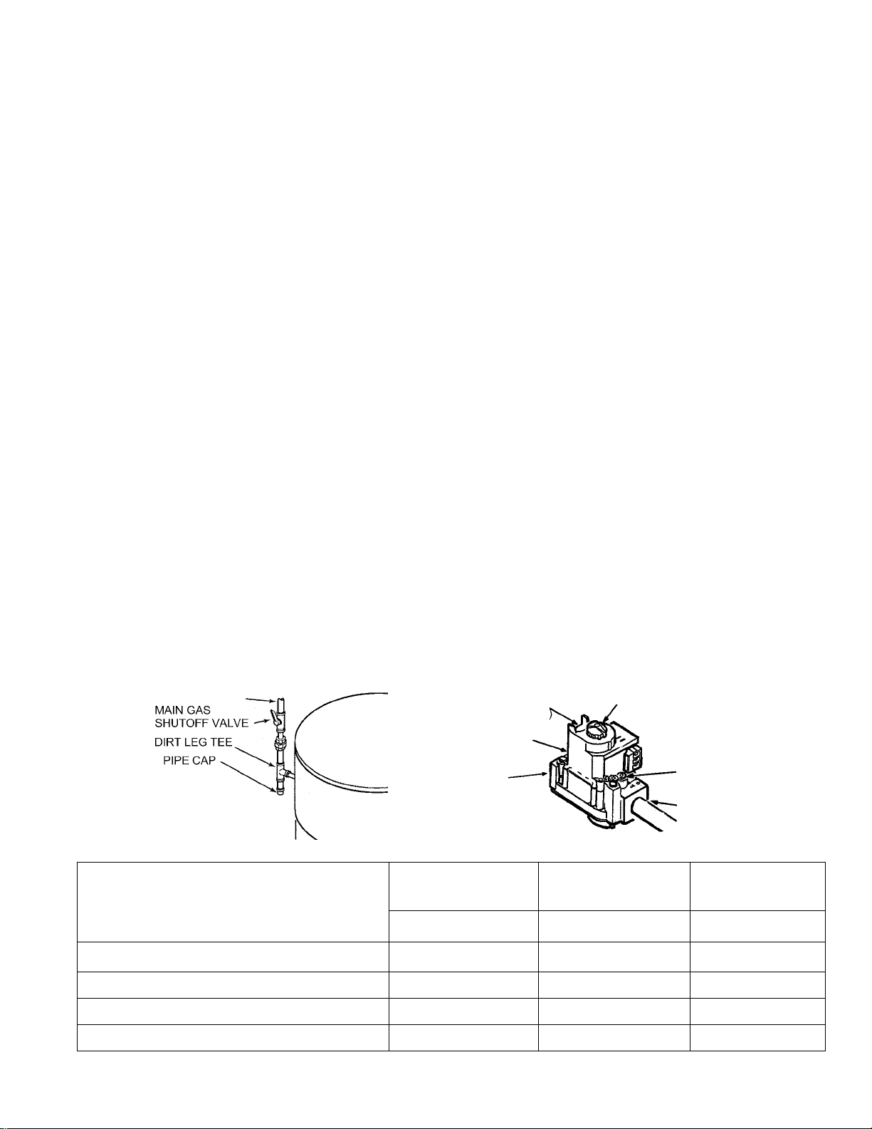
GAS REQUIREMENTS
NOTE: Pressure without capacity will result in lockout. Follow the piping guidelines in the
installation manual. The supply gas pressure is normally measured at the dirt leg or at the inlet gas
pressure tap on the gas valve. This reading must be measured with ‘flowing’ gas.
The manifold gas pressure is measured at the manifold pressure tap on the gas valve when the
gas is flowing. The gas valves used on all BTH water heaters are 24 VAC combination step open
ing gas valves. They incorporate the main valve and pressure regulator into one body.
REGULATED GAS SUPPLY LINE
GAS SUPPLY SPECIFICATIONS
NATURAL GAS NATURAL GAS PROPANE GAS
PRESSURE REGULATOR
ADJUSTMENT
(COVER screw'
INLET PRESSURE
TAP
GAS INLET
BTH 120 & 250 BTH 150 & 199
GAS VALVE ON/OFF
TH & TR TERMINALS
(MAIN VALVE)
VIANIFOLD
PRESSURE TAP
GAS OUTLET
BTH 120, 150 &
199
Max. Gas Supply Pressure Inches W.C.
Nominal Gas Supply Pressure Inches W.C.
Minimal Gas Supply Pressure Inches W.C.
Manifold Pressure Inches W.C.
A. O. Smith Water Products Co.
Ashland City, Tennessee © 2004
12.0 (3 kPa) 12.0 (3 kPa) 14.0(3.45 kPa)
7.0 (1.75 kPa) 7.0 (1.75 kPa) 11.0 (2.74 kPa)
5.5 (1.37 kPa) 4.5 (1.12 kPa) 11.0 (2.74 kPa)
4.0 (1 kPa) 3.5 (0.8 kPa) 10.0 (2.5 kPa)
Technical Training Department
TC-044 Revision 6
Page 5
BTH SERVICE HANDBOOK
NSTALLATION
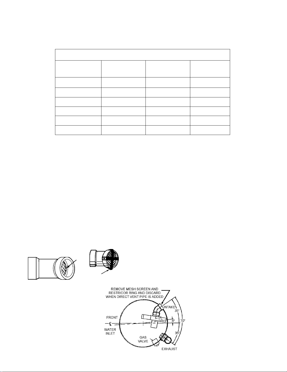
VENTING
Equivalent Feet of Pipe Intake or Exhaust
VENT LENGTH TABLE
NUMBER OF 90°
ELBOWS
ONE (1)
TWO (2)
THREE (3) 7 35 105
FOUR (4) 7
FIVE (5) 7
SIX (6) 7
3” MINIMUM
PIPE (FEET)
7 45 115
7
3” MAXIMUM
PIPE (FEET)
40 110
30 100
- 95
-
4” MAXIMUM
PIPE (FEET)
90
4-inch PVC may be used for a MAXIMUM intake of ONE HUNDRED TWENTY (120) EQUIVALENT
FEET and a MAXIMUM exhaust of ONE HUNDRED TWENTY (120) EQUIVALENT FEET The
maximum number of 90° elbows with the 4-inch venting is six (6) on the intake and six (6) on the
exhaust. A 90° elbow is equal to five (5) equivalent feet of pipe. One (1) 90° elbow is equal to two
(2) 45° elbows. Any venting configuration using less than 50 equivalent feet should use 3-inch vent
ing. See Vent Length Table.
The 3-inch venting terminals (provided) must be used with the 4-inch venting by adding 4x3
reducing coupling at the venting terminals. A reducing coupling is also needed immediately after
the condensate elbow (exhaust) and immediately before the 3-inch blower adapter (intake) if direct
venting is installed. See Vent Length Table.
DIRECT VENTING
The air intake provided on the unit contains a mesh screen (see Figure below) to prevent large par
ticles from entering the unit.
3” (7.6CM) 45° PVC ELBOW WITH MESH SCREEN
MESH
SCREEN
WARNING
WHEN THE UNIT IS TO
BE SETUP AS A DIRECT VENT, THE
MESH SCREEN MUST BE REMOVED.
THE INLET VENT PIPE MAY THEN BE
GLUED TO THE AIR INTAKE (see follow
RESTRICTOR
ing Figure) PROVIDED ON THE UNIT.
Technical Training Department
TC-044 Revision 6
A. O. Smith Water Products Co.
Ashland City, Tennessee © 2004
Page 6
IC
IC
IC
IC
IC
IC
IC
IC
IC
IC
—p l_l l_l
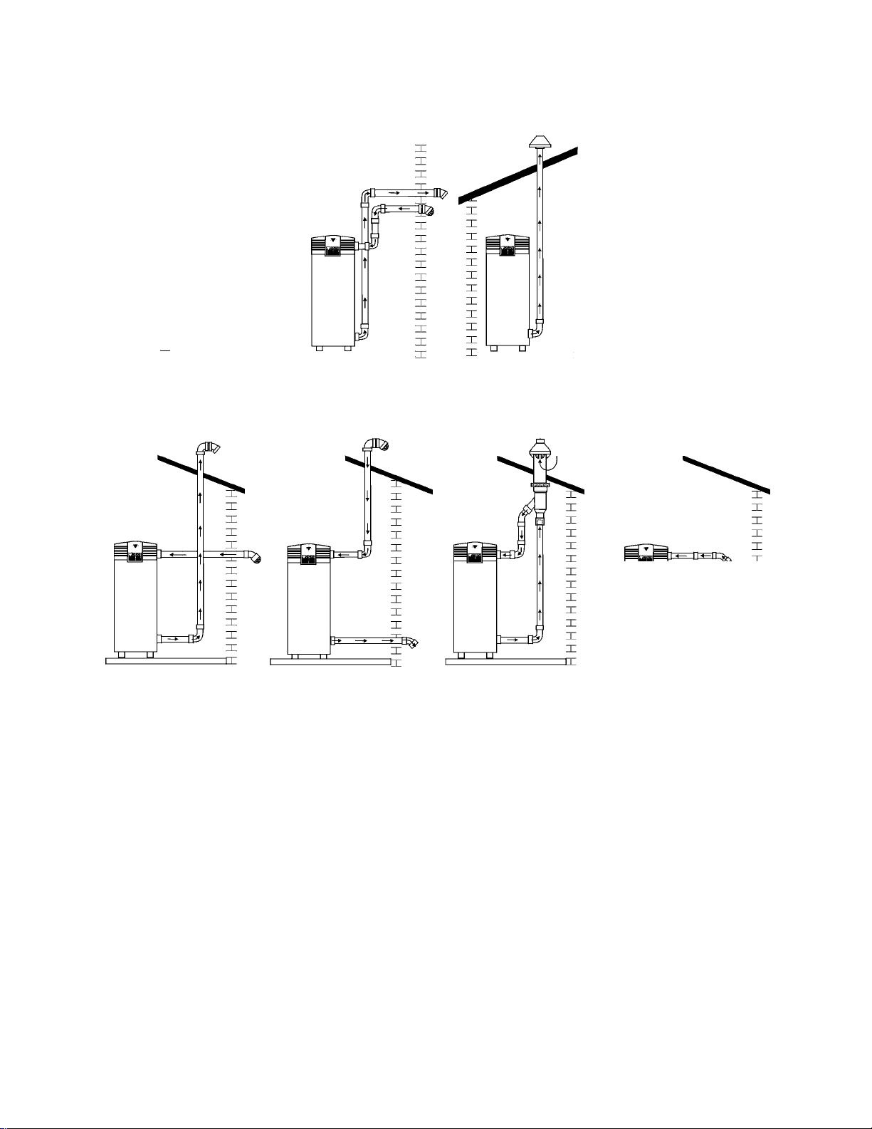
SEALED DIRECT
VENT VERTICAL
z[#
BTH SERVICE HANDBOOK
INSTALLATION
VENTING CONFIGURATIONS
SEALED DIRECT
VENT SIDEWALL
INDOOR CONVENTIONAL
VERTICAL
LE
IE
EE
EE
EE
EE
EE
EE
EE
EE
INDOOR CONVENTIONAL
SIDEWALL
=
EE
SEALED DIRECT VENT
HORIZONTAL INTAKE
VERTICAL EXHAUST
This unit can be vented using only PVC (Class 160, ASTM D-2241; Schedule 40, ASTM D-1785; or
Cellular Core Schedule 40 DWV, ASTM F-891), Schedule 40 CPVC (ATSM F-411), or ABS (ASTM
D-2661) pipe. The fittings, other than the TERMINATIONS should be equivalent to PVC-DWV fit
tings meeting ASTM D-2665 (Use CPVC fittings, ASTM F-438 for CPVC pipe and ABS fittings,
ASTM D-2661/3311 for ABS pipe. If CPVC or ABS pipe and fittings are used, then the proper
cement must be used for all joints, including joining the pipe to the Termination Tee (PVC Material).
PVC Materials should use ASTM D-2564 Grade Cement; CPVC Material should use ASTM F-493
Grade Cement and; ABS Materials should use ASTM D-2235 Grade Cement.
For water heaters in locations with high ambient temperatures (above 100°F) and/or insufficient
dilution air, it is recommended that CPVC or ABS pipe and fittings (MUST USE SUPPLIED VENT
TERMINAL) be used.
SEALED DIRECT VENT
VERTICAL INTAKE
HORIZONTAL EXHAUST
VENTING MATERIALS
SEALED DIRECT VENT
W/ CONCENTRIC VENT
VERTICAL TERMINATION
SEALED DIRECT VENT
W/ CONCENTRIC VENT
HORIZONTAL TERMINATION
A. O. Smith Water Products Co.
Ashland City, Tennessee © 2004
Technical Training Department
TC-044 Revision 6
Page 7
ВТН SERVICE HANDBOOK
INSTALLATION
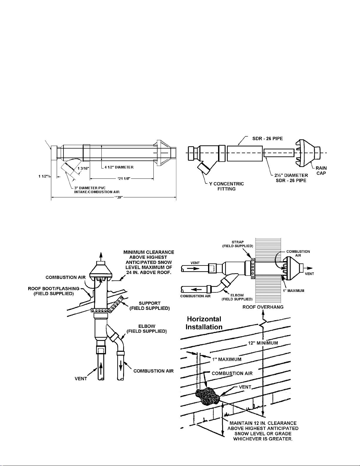
CONCENTRIC VENT TERMINATION
The concentric vent termination kit, Part No. 194451-000 can be used on BTH 120 - 250 Cyclone
XHE water heaters. It adds zero equivalent feet to the vent system. Below are some general appli
cation and installation guidelines for the concentric vent kit. Refer to the accompanying literature
and the water heater installation manual for complete venting installation instructions.
This concentric vent termination kit may be used with 3 or 4 in. diameter pipe systems. When con
necting to a 4 in. diameter pipe system a 3 x 4 in. field supplied reducer is to be installed at the
intake and exhaust connection of the concentric vent termination kit. See water heater installation
and operation manual for venting specification
3" DIAMETER
PVC VENT/EXHAUST
4" DIAMETER
Dimension 21 1/8 in. may be lengthened to 60 in. maximum. Dimension 21 1/8 in. may also be
shortened by cutting the pipes, provided in the kit, to 12 in. minimum. Dimension 39 will change
accordingly as dimension 21 1/8 in. is lengthened or shortened
MAINTAIN 12 IN.
VENT
(18 IN. FOR CANADA)
Vertical Installation
Technical Training Department
TC-044 Revision 6
A. O. Smith Water Products Co.
Ashland City, Tennessee © 2004
Page 8
BTH SERVICE HANDBOOK
INSTALLATION
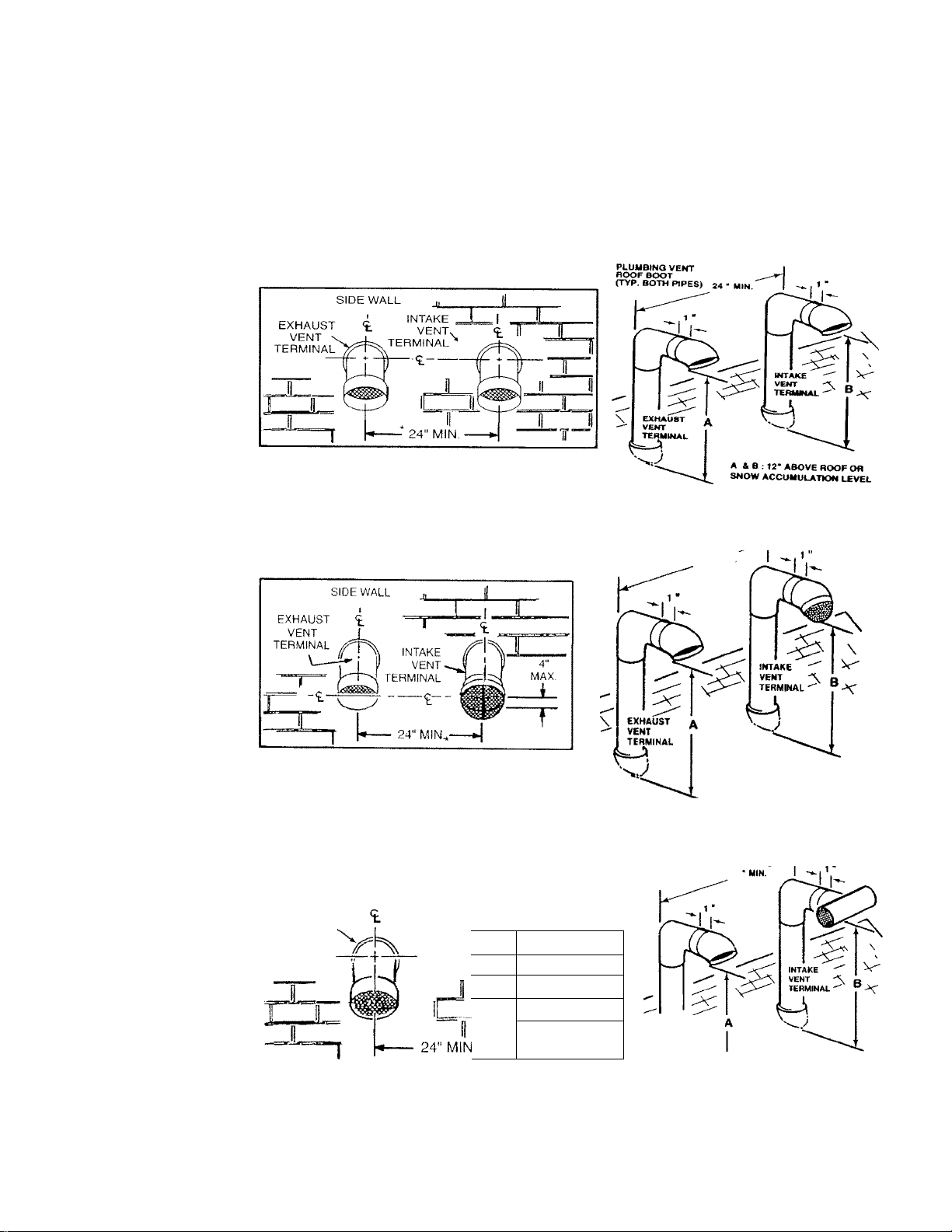
VENTING CLEARANCES
This illustrates the exterior clearances for these BTH units when installed as direct vent heaters.
NOTE: 24 inches between inlet and outlet is a MINIMUM. Greater distance is recommended.
In colder climates increasing the 24” minimum to a maximum practical distance will reduce the
possibility of frost over from side winds blowing exhaust vapors into the air intake.
BTH MODEL 120
BTH MODEL 150-199
BTH MODEL 250
EXHAUST
VENT
TERMINAL
SIDE WALL
INTAKE
VENT^
TERMINAL
--J II
-JU iL_«
■ —*1
PLUMBING VENT
ROOF BOOT
(TVP. BOTH PIPES) 24* MIN
PLUMBING VENT
ROOF BOOT
(TYP. BOTH PIPES) 24
—] II
1! i
EXHAUST
n II
II
VENT
TERMINAL
A SB; 12° ABOVE ROOF OR
SNOW ACCUMULATION LEVEL
A & B ; 12* ABOVE ROOF OR
SNOW ACCUMULATION LEVEL
A. O. Smith Water Products Co.
Ashland City, Tennessee © 2004
Technical Training Department
TC-044 Revision 6
Page 9
BTH SERVICE HANDBOOK
NSTALLATION
EXTERIOR SIDEWALL CLEARANCES
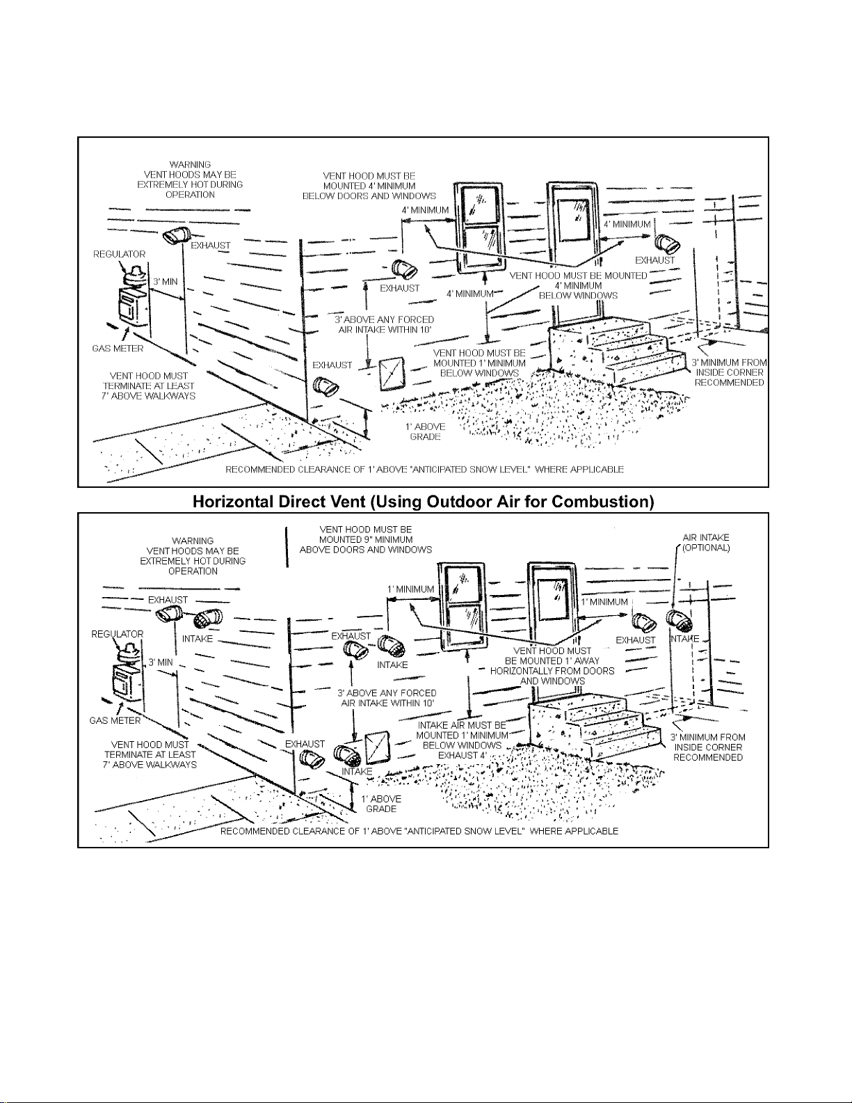
Horizontal Vent (Using Room Air for Combustion)
When multiple units are directly vented through a wall, all intake vent terminals must be no lower
than the highest exhaust vent terminal.
CAUTION
DO NOT TERMINATE THE VENTING WHERE NOISE FROM THE EX
HAUST OF INTAKE WILL BE OBJECTIONABLE. THIS INCLUDES LOCATION CLOSE TO
OR ACROSS FROM WINDOWS AND DOORS. AVOID ANCHORING THE VENT AND
INTAKE PIPES DIRECTLY TO FRAMED WALLS, FLOORS OR CEILINGS UNLESS RUB
BER ISOLATION PIPE HANGERS ARE USED. THIS PREVENTS ANY VIBRATIONS
FROM BEING TRANSMITTED INTO THE LIVING SPACES.
Technical Training Department
TC-044 Revision 6
8
A. O. Smith Water Products Co.
Ashland City, Tennessee © 2004
Page 10
ВТН SERVICE HANDBOOK
INSTALLATION
AIR REQUIREMENTS
MINIMUM AIR FOR COMBUSTION
10 Cubic Feet of Air Per 1000 BTUH
2.5 CU.
EXCESS
FT
AIR
Stoichiometric or theoretical complete combustion requires 10 cubic feet of air per 1000 BTUH of
gas input. The National Fuel Gas Code also recommends an additional 2.5 cu.ft. of “excess air”.
This 12.5 cu.ft. minimum supply air per 1000 BTUH input applies to natural and propane gas mod
els.
The National Fuel Code also specifies minimum make-up air opening sizes for various building
installations (Ref: NFPA 54, ANSI Z223.1, sec 5.3).
MAKE-UP AIR
Direct Vent Installation
This model is approved for direct venting either horizontally or vertically or conventional venting
horizontal or vertical. Direct venting avoids using room air for combustion and eliminates the need
for additional air intake ducts.
A. O. Smith Water Products Co.
Ashland City, Tennessee © 2004 9
Technical Training Department
TC-044 Revision 6
Page 11

BTH SERVICE HANDBOOK
INSTALLATION
MAKE-UP AIR
Direct Communication
12”
Each opening shall
have a free area not
less than:
1 square inch per
4000 BTUH total input
all appliances within
the enclosure
Inlake Air
Iniciko Air Opening
L
Opening
12”
A fresh supply of make-up air for combustion can be supplied to the heater through make-up air
openings, which directly communicate with the out of doors. Two openings are required — one
within 12 inches of the top of the enclosure and one within 12 inches of the bottom of the enclosure.
Each opening shall have a free area of not less than 1 square inch per 4000 BTUH of the total input
of all appliances within the enclosure.
The lower opening is primarily providing combustion air. The upper opening is providing vent dilu
tion air and acts as a relief opening for flue gases should the vent become obstructed or a down
draft condition occur.
MAKE-UP AIR Vertical Ducts
Air Intake Ducts
12”
Each opening shall
have a free area not
less than:
1 square inch per
4000 BTUH total input
all appliances within
the enclosure
12”
Often it is more practical to install vertical make-up air ducts to the outdoors. Again, two openings
are required — within 12 inches (30 cm) of the top of the enclosure and one within 12 inches (30
cm) of the bottom of the enclosure. Each opening shall have a free area of not less than 1 square
inch per 4000 BTUH of the total input of all appliances within the enclosure.
Technical Training Department
TC-044 Revision 6
10
A. O. Smith Water Products Co.
Ashland City, Tennessee © 2004
Page 12

BTH SERVICE HANDBOOK
NSTALLATION
MAKE-UP AIR
Horizontal Ducts
E.K ÌÌ opiMiin<| sImII
hriVH <-1 liee nnl
less
IImm:
1 s(|ii<iie im li pel
vomì BTUH Ifil.il inpiil ,
«ill «ippliano os within
llie ent Insule
Air Intake Ducts
J
12”
12’
When the heater is installed in an interior room with no roof access for vertical ducts, horizontal
make-up ducts should be installed. When using horizontal ducts, two openings are required - within
12 inches (30 cm) of the top of the enclosure and one within 12 inches (30 cm) of the bottom of the
enclosure. Each opening shall have a free area of not less than 1 square inch per 2000 BTUH of
the total input of all appliances within the enclosure.
INSUFFICIENT MAKE-UP AIR
Backdraft
rr
Insufficient make-up air is a major cause of combustion problems. One common example is in a
restaurant installation where exhaust vent equipment was not considered in sizing make-up air
requirements. This may result in air being backdrafted by the restaurant exhaust equipment
through the heater causing flue gas spillage, flame roll out, improper combustion, inconsistent pilot
operation, and/or erratic heater shutdown.
A possible solution to this situation would be to use a BTH with direct venting.
A less common service issue associated with a backdraft or negative pressure room would be the
opening or closing of air pressure switches. This may result in erratic or no heater operation.
A. O. Smith Water Products Co.
Ashland City, Tennessee © 2004
11
Technical Training Department
TC-044 Revision 6
Page 13
BTH SERVICE HANDBOOK
INSTALLATION
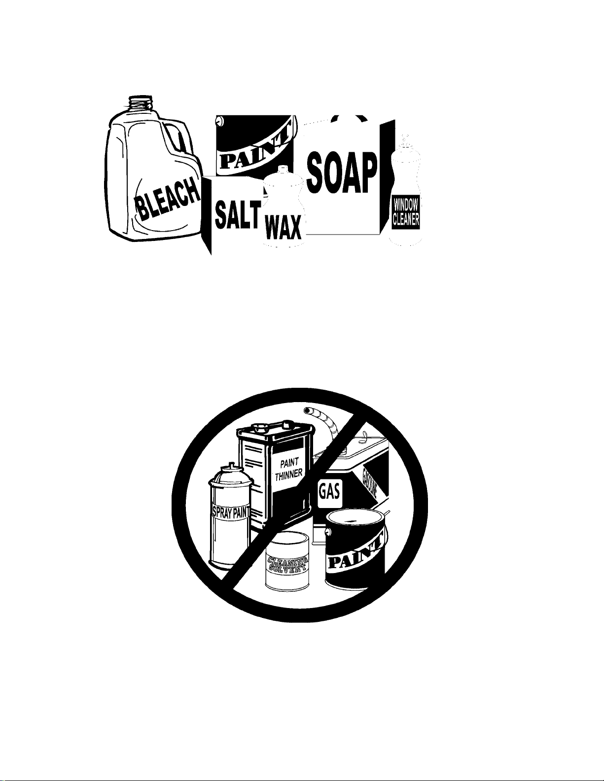
CONTAMINATED AIR
^ RUST
CHIPS
Along with adequate make-up air, the quality of the air is important. Contaminants in combustion air
can lead to premature heater failure. Vapors from bleaches, soaps, salts, etc. are drawn into the
combustion chamber with the make-up air and, once fired, mix with water vapor in the gasses to
form extremely corrosive hydrochloric or hydrofluoric acid and other corrosive by-products. Dust
drawn in may build up on the blower or clog the main burner ports. Also, be certain to examine the
exterior area around the air intake of a direct vent installation for the contaminants.
FLAMMABLE ITEMS
Flammable items or pressurized containers or any other potentially hazardous articles must never
be placed on or adjacent to the heater. Open containers of flammable material should not be stored
or used in the same room with the heater or in the area of the exterior air intake of a direct vent
installation. Direct venting does not eliminate the need to remove flammable or corrosives from the
area surrounding the heater.
Technical Training Department
TC-044 Revision 6 12
A. O. Smith Water Products Co.
Ashland City, Tennessee © 2004
Page 14
BTH SERVICE HANDBOOK
INSTALLATION
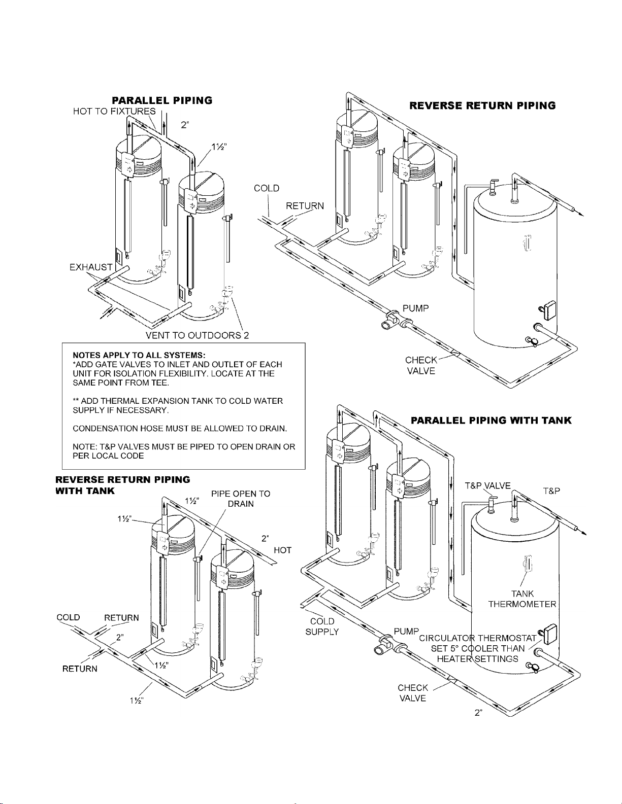
MULTIPLE UNIT — WATER PIPING
A. O. Smith Water Products Co.
Ashland City, Tennessee © 2004 13
Technical Training Department
TC-044 Revision 6
Page 15

ВТН SERVICE HANDBOOK
INSTALLATION
CONDENSATION
The average dewpoint of natural gas flue products is 127° F. Propane flue products is 119° F. With
70° F ambient air temperature and 180° F stored water temperature, exhaust gas will be approxi
mately 140° F. Recommended starting point for water storage is 120° F.
The extra high thermal efficiency of the BTH will result in condensation in the flue passage. The fol
lowing answers common questions about this condensation.
CAN I DRAIN THIS CONDENSATION TO A FLOOR DRAIN? The “Corrosion Resistance of Cast
Iron Soil Pipe” by the Ductile Metals Association (formally the Cast Iron Soil Pipe Institute) states
that:
“Internal corrosion of cast iron soil pipe and fittings can be caused by strong acids or other reagents
having an acidity of pFI 4.3 or less if allowed to contact cast iron pipe for an extended period of time
without sufficient dilution to raise the pH valve about 4.3. By avoiding low pH discharges, internal
corrosion problems can be limited or eliminated, assuring the owner many years of service.”
WHAT ABOUT THE pH VALUES OF CONDENSATE AND SODA POP? The pH of the BTH con
densate average 4.5 which is approximately 4 times less concentrated than the limit of 4.3 recom
mended by the DMA. Any water flow in the drain rapidly dilutes the condensate even more. A can
of leading carbonated cola drink measured a pH of 2.5 which is 300 times more concentrated than
the BTH condensate.
WHAT DOES THE pH SCALE MEAN? The pH value is a measure of acidity of alkalinity. A pH of
7 is neutral. Numbers from 7 to 1 indicate increasing acidity and numbers from 7 to 14 indicate
increasing alkalinity. The pH scale is similar to the Richter scale used to measure earthquakes.
Each number indicates a change of 10 times the concentration of the previous value. A pH 6 is 10
times more concentrated than a pH 7, a pH 5 is (10x10) 100 times pH 7 and pH 4 is (10x10x10)
1,000 times pH 7, etc.
WHAT ABOUT CONDENSATE NEUTRALIZERS? Condensate neutralizers are usually not nec
essary. A condensate neutralizer is easy to make by filling a short length of 2” or 3” PVC pipe with
landscape marble chips, capping it and installing it in series with the condensate drain of the equip
ment. Most commercial neutralizers are off the market because of poor demand for the product.
Condensation from the exhaust vent piping and tank internal flue way must be allowed to drain. A
“blocked flue” indication will often be your first indication that condensate is not draining.
Technical Training Department
TC-044 Revision 6 14
A. O. Smith Water Products Co.
Ashland City, Tennessee © 2004
Page 16
BTH SERVICE HANDBOOK
OPERATION
OPERATION
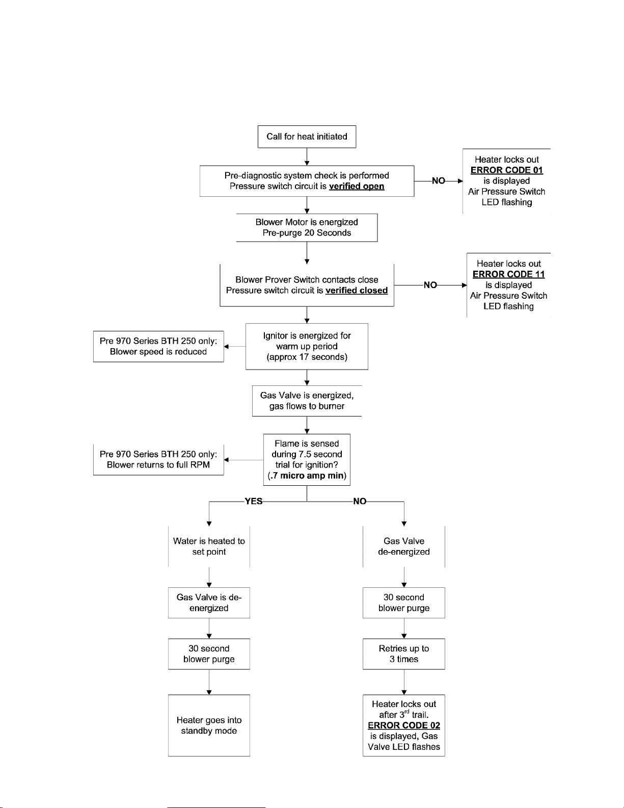
SEQUENCE OF OPERATION
A. O. Smith Water Products Co.
Ashland City, Tennessee © 2004 15
Technical Training Department
TC-044 Revision 6
Page 17
BTH SERVICE HANDBOOK
OPERATION
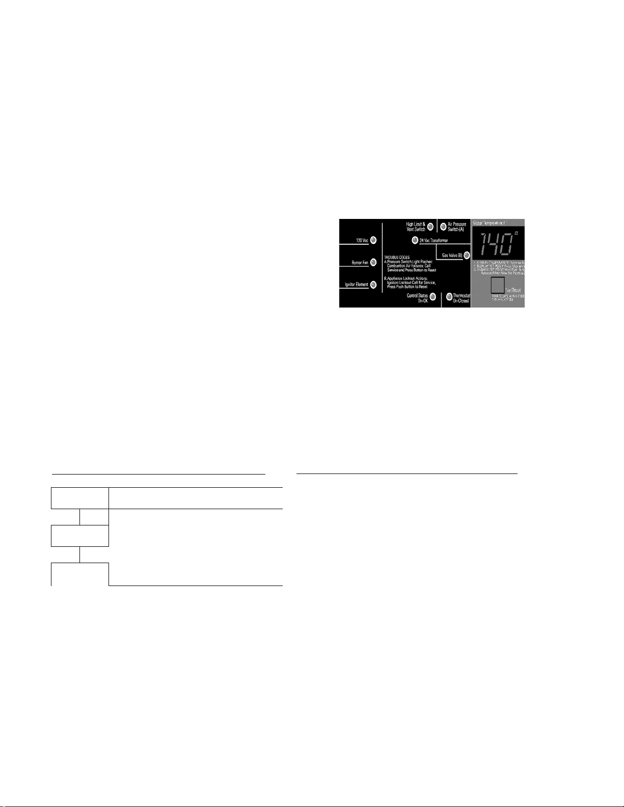
CONTROLS
NORMAL INDICATIONS / READINGS / SETTINGS
During Call for Heat
On/Off switch in the “on” position
DISPLAY PANEL (CONTROL PANEL)
Water Temperature F° — current average
tank water temperature displayed
120 VAC LED light on
24 VAC LED light on
High LimitA/ent Switch LED light on
Blower (while blower is running) LED light
on
Air Pressure Switch (while blower is
running) LED light on
Control Status LED light on
Gas Valve (during ignition period and
heating cycle) LED light on
The water temperature inside the tank must be below the current temperature setting to activate a
call for heat. Pressing the Set/Reset button approximately 4-6 seconds after powering up the
water heater will reveal the current temperature setting. See the instructions below for how to view
or change temperature settings.
Power On Display Sequence / Indication
00
r
120
r
12
--------
M Press Set/Reset button at this moment |
¡to initiate a control operational check i
1 Factory default setting - 12. ¡
¡Tank Temperature
Press Set/Reset button to view or
ladjust current temperature setting.
Power on display. j
¡Supply voltage i
j ¡Temperature Offset. i
To View Or Change Temperature Settings
Press the Set/Reset button once to view the current temperature setting.
' 1
Press and hold the Set/Reset button down to change the current setting.
When pressed and held down it will raise/lower the setting,
quickly releasing and pressing down/holding again will switch
between raising and lowering. When the desired setting is
reached release the button.
The control must satisfy a call for heat with the new setting for the
new setting to remain in memory. If the water heater does not
satisfy a cali for heat with the new setting, the new setting is lost and
the previous setting remains in effect.
Technicai Training Department
TC-044 Revision 6
16
A. O. Smith Water Products Co.
Ashiand City, Tennessee © 2004
Page 18
BTH SERVICE HANDBOOK
OPERATION
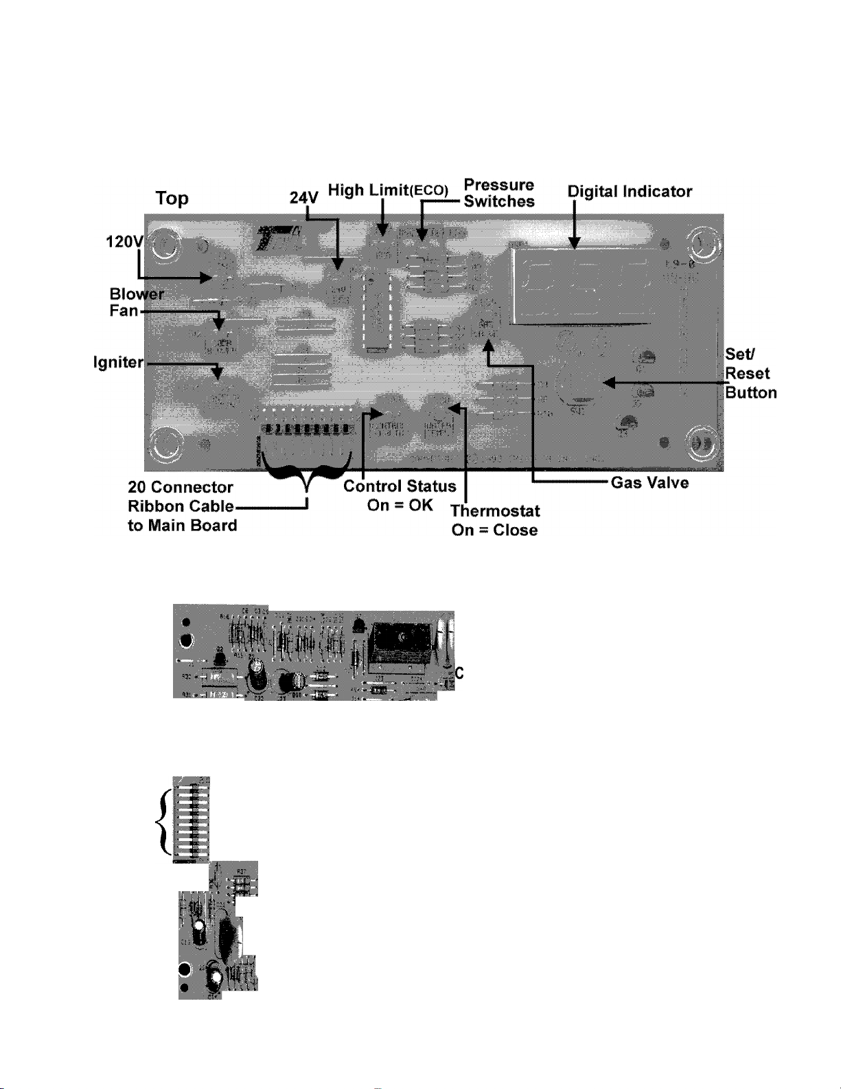
CIRCUI BOARDS
DISPLAY CIRCUIT BOARD
IGNITION CIRCUIT BOARD
'1... 2.1.4
I
N8
■ -1 - •
■ ■ *
20 Conductor
. Ribbon Cable
to Display Board • • ‘ ^ ^ 'j. J 4—
is»
.....................................
m
■ -tj tCN2 , 12 3
, (tHaií>í*3í--í
....
, J .^Transformer
CN1
CN6 j:r>
1 2
' i '*
1 2 3 ;
3 2 1
6 5 4
4»-
1 1 2 •
.Temperature/
Eco Probe (Upper)
Temperature
Probe #2 (Lower)
Igniter
Blower
To Junction Box
1,3 Gas Valve
2 Flame Sensor
4,6 Pressure Switches
5 Ground
A. O. Smith Water Products Co.
Ashland City, Tennessee © 2004
17
Technical Training Department
TC-044 Revision 6
Page 19
BTH SERVICE HANDBOOK
TROUBLESHOOTING
TROUBLESHOOTING
PRE-SERVICE TIPS
CHECK THAT:
• Insure 120 VAC power supply has correct polarity — check neutral
(white) wire to ground with volt meter. It should read “0” volts.
• Tank is full of water
• Exhaust and intake vent do not exceed allowable limits
• All plugs into boards are secure
• Condensate hose is drained and open
• Proper (natural or propane) gas is supplied
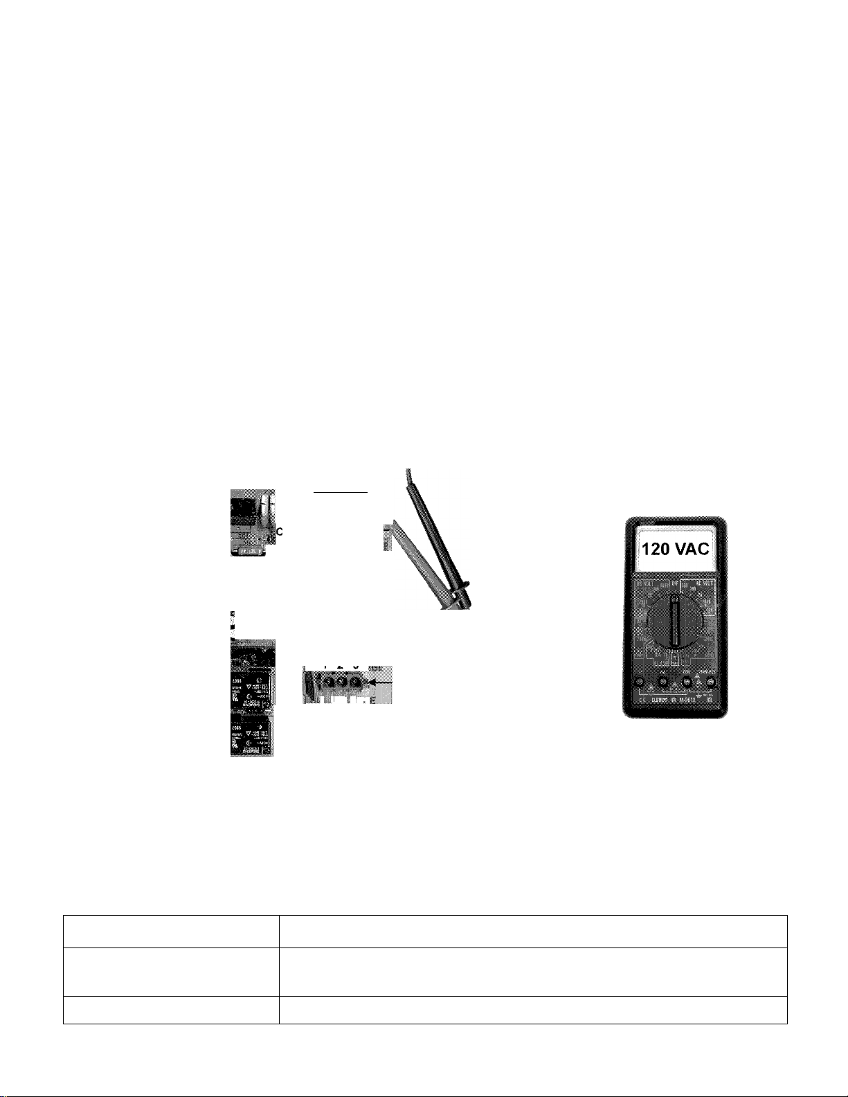
120 VAC TO CONTROL
STEP 1 120 VAC TO CONTROL BOARD
j1 2 3 4 N«!
M. -a«*-
1 2
:1|CN4 ■ . ■ ^
it;* ViiRitcB*
iCN2 . 12 3
STEP 1: CHECK FOR 120 VAC TO CONTROL BOARD CN1 TERMINAL.
Condition:
• Disconnect plug from CN1 terminal.
• On/Off switch is on.
12 3 4
■ ■
CN1
• G 5 4 •
. 0 , ■
j i.mi TR'ig
mt
To Juiiction Box
■ Black
" White
" Green
Check for 120 VAC black wire terminal white wire on plug.
IF... THEN
120 VAC is not present
120 VAC is present reconnect CN1 plug, continue to Step 2.
Technical Training Department
TC-044 Revision 6
check On/Off switch, turn switch on, replace On/Off switch if defective, restore
power to the water heater.
18
A. O. Smith Water Products Co.
Ashland City, Tennessee © 2004
Page 20
BTH SERVICE HANDBOOK
TROUBLESHOOTING
TRANSFORMER
STEP 2
120 VAC TO TRANSFORMER
I 120V
CO
1
m-%
1
r'
^ o
.
i'iC —
>1
mm
^ lonThois
STEP 2: CHECK FOR 120 VAC TO TRANSFORMER FROM PIN 1 AND 2 ON CONTROL
BOARD CN4 TERMINAL.
Condition:
• Disconnect CN4 plug from control board.
• On/Off switch is on.
Check for 120 VAC between pin 1 and 2 at CN4 on the control board as illustrated above. Perform
this test with the CN4 plug disconnected and the On/Off switch turned on.
IF... THEN
120 VAC is not present
120 VAC is present reconnect CN4 plug to control board, continue to Step 3.
check CN1 plug connection
replace control board if Step 1 has been performed and results were successful.
A. O. Smith Water Products Co.
Ashland City, Tennessee © 2004 19
Technical Training Department
TC-044 Revision 6
Page 21
BTH SERVICE HANDBOOK
TROUBLESHOOTING
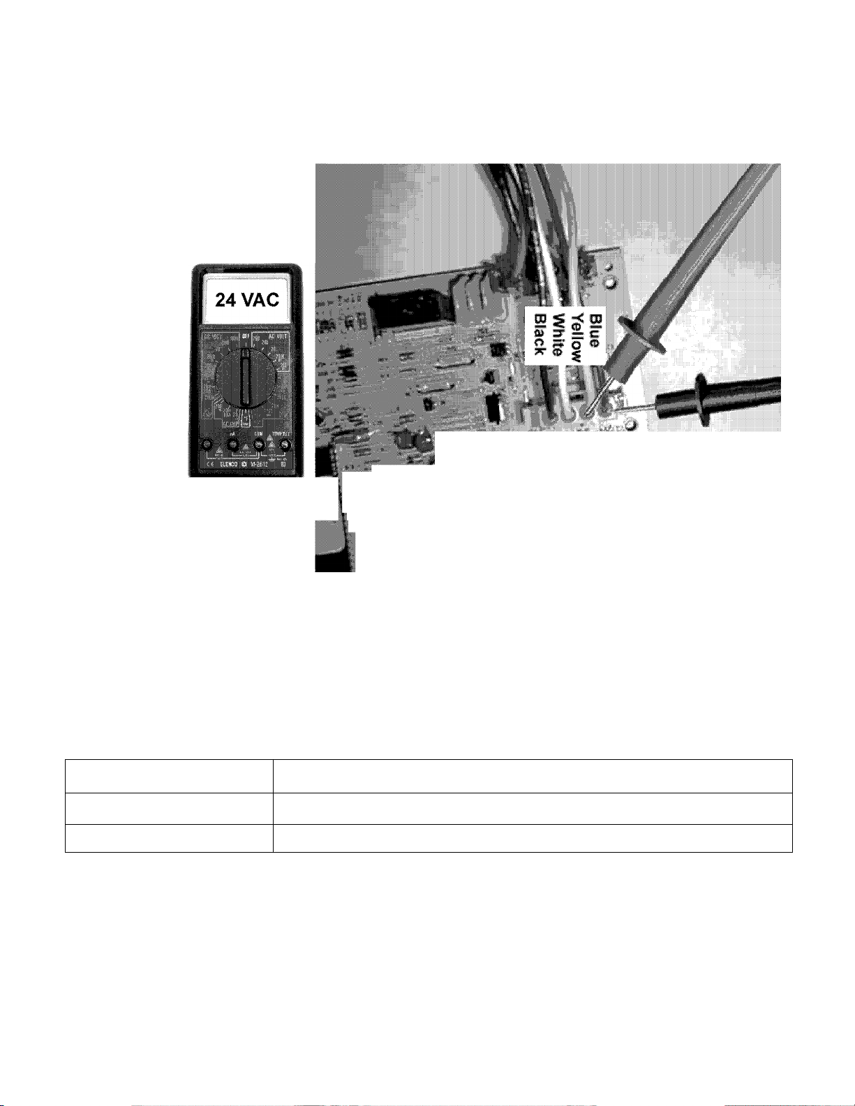
TRANSFORMER (CONTINUED)
STEPS
24 VAC FROM TRANSFORMER
‘m ■'■
STEP 3: CHECK FOR 24 VAC AT TRANSFORMER CN4 PLUG ON CONTROL BOARD.
Condition:
• CN4 is plugged into control board.
• On/Off switch is on.
Insert meter probes into back of CN4 plug on pins 3 and 4 (blue and yellow wires) with CN4
plugged in and power on.
IF... THEN
24 VAC is not present
24 VAC is present
replace transformer if Steps 1 and 2 were performed and results were successful.
continue to Step 4.
Technical Training Department
TC-044 Revision 6
20
A. O. Smith Water Products Co.
Ashland City, Tennessee © 2004
Page 22

BTH SERVICE HANDBOOK
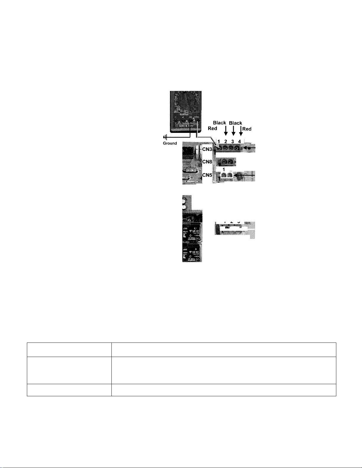
STEP 4 24 VAC TO ECO
TROUBLESHOOTING
ECO CHECK
24 V
r
Ty
Black Black
Redj I j |Red
Ground
_ t.
1 2 3
I ^'12 •
m
7^CN8 ◄
1 2
■CN5 -
I 1 I 'i A
STEP 4: CHECK FOR 24 VAC BETWEEN PIN 4 ON CONTROL BOARD TERMINAL CN3 AND
GROUND.
Condition:
• Disconnect CN3 plug from control board.
• On/Off switch is on.
Check for 24 VAC between pin 4 of the CN3 terminal on the control board and ground.
IF... THEN
24 VAC is not present
replace the control board if Steps 1, 2, and 3 have been performed and the results
were successful.
^Temperature/
Eco Probe (Upper)
^Temperature
-----
Probe #2 (Lower)
-Igniter
24 VAC is present continue to Step 5.
A. O. Smith Water Products Co.
Ashland City, Tennessee © 2004
21
Technical Training Department
TC-044 Revision 6
Page 23
BTH SERVICE HANDBOOK
TROUBLESHOOTING
ECO CHECK (CONTINUED)
STEPS 24 VAC FROM ECO
Ì
24 V
1 2
.Temperature/
Eco Probe (Upper)
Temperature
», Probe #2 (Lower)
2 I-
Igniter
IcN4 .^ ^ ^
' Í ^
. [ *
TCN2 1 2 3
■ 1 O *5
CN1 HtnwISKflp^—To Junction Box
I I
6 5 4
Transformer
— Blower
1, 3 Gas Valve
2 Flame Sensor
• 4, 6 Pressure Switches
5 Ground
STEP 5: CHECK FOR 24 VAC BETWEEN PIN 1 ON CN3 PLUG AND GROUND.
Condition:
• Reconnect CN3 plug to control board.
• On/Off switch is on.
Insert one meter probe into the back of CN3 plug pin 1, check for 24 VAC between here and ground
with CN3 plugged in and power on. (See illustration above for pin number locations.)
IF... THEN
make sure water temperature in tank is below 160° F, press Set/Reset button on
24 VAC is not present
24 VAC is present continue to Step 6.
Technical Training Department
TC-044 Revision 6 22
display panel, replace upper temperature/ECO probe if tank water temperature is
below 160 and Step 4 has been performed and results were successful.
A. O. Smith Water Products Co.
Ashland City, Tennessee © 2004
Page 24

BTH SERVICE HANDBOOK
TROUBLESHOOTING
TEMPERATURE PROBE
STEP 6 TEMPERATURE PROBE RESISTANCE
LOWER
ohms
TEMPERATURE PROBE PLUG
1
r
STEP 6: CHECK RESISTANCE OF THERMISTOR IN UPPER AND LOWER TEMPERATURE
PROBES.
Condition:
• Disconnect CN3 and CN8 plugs from control board.
• On/Off switch is off.
• Multimeter is set to lowest ohms scale above expected resistance.
Check resistance between black wire connects on CN3 and CN8 plugs as shown in illustration
above.
IF... THEN
ohm reading does not approximately correspond to table at given
temperatures
ohm reading does approximately correspond to table at given
temperatures
WATER TEMP
OHMS RESISTANCE
X
3 40 26,435
21 70 11,974
37.5 100 5,862
49 120 3,780
54.5 130 3,066
60 140 2,503
71 160 1,698
82 180 1,177
°F
NOTE: The upper and lower temperature probes contain
thermistors which are heat sensitive resistors. The control
board interprets changes in thermistor resistance as
changes in water temperature.
These thermistors are very reliable and should only be
replaced when:
The resistance test indicates an “open” (infinite resistance)
or a “direct short” (no resistance) circuit.
The nature of the service problem is temperature control
and the resistance readings are significantly off when com
pared to the values in the table here at the given tempera
ture.
replace temperature probe if thermistor is open,
shorted, or resistance value is off significantly.
continue to Step 7.
A. O. Smith Water Products Co.
Ashland City, Tennessee © 2004 23
Technical Training Department
TC-044 Revision 6
Page 25

BTH SERVICE HANDBOOK
TROUBLESHOOTING
PRESSURE SWITCH CONTINUITY
STEP 7 PRESSURE SWITCH CONTINUITY TEST
Notes:
Low Gas Pressure Switch
(BTH 120 & 250 only)
is instailed on the iniet
side of the Gas Valve.
N.O. = Normally Open
N.C. = Normally Closed
Blocked Inlet Switch
N. C. Contacts
Blower Prover Switch
N. O. Contacts
Blocked Outlet Switch
N. C. Contacts
Gas Valve - Top View
STEP 7: CHECK FOR CONTINUITY BETWEEN PRESSURE SWITCH TERMINALS WITH
WIRES REMOVED.
Condition:
• On/Off switch is off.
• All wires are disconnected from all pressure switches.
• Multimeter is set to lowest ohms scale.
IF... THEN
blocked inlet switch does not show continuity replace switch.
blocked inlet switch does show continuity
blower proving switch does show continuity replace switch.
blower proving switch does not show continuity continue.
low gas pressure switch does not show continuity
low gas pressure switch does show continuity continue.
blocked outlet pressure switch does not show continuity replace switch.
blocked outlet pressure switch does show continuity
continue.
check for minimum supply gas
pressure of
5.0” W.C. natural gas
9.0” W.C. LP gas
replace switch if gas pressures
are above these minimums.
reconnect all wires to pressure
switches; continue to Step 8A.
Technical Training Department
TC-044 Revision 6 24
A. O. Smith Water Products Co.
Ashland City, Tennessee © 2004
Page 26

BTH SERVICE HANDBOOK
TROUBLESHOOTING
STEP 8A 120 VAC TO BLOWER
BLOWER
120V
|iipii|M
« 3 V
Blower
.-321
CN6 I
STEP 8A: CHECK FOR 120 VAC TO BLOWER FROM CN2 PLUG PIN 1 AND 2.
Condition:
• Reconnect all plugs to control board.
• On/Off switch is on.
• Call for heat is activated.
Insert meter probes into back of CN2 plug on pins 1 and 2 with CN2 plugged in, power on, and a
call for heat activated.
IF... AND THEN
120 VAC is not
present
replace the control board if call for heat is active and Step 7 has been
performed and results were successful.
120 VAC is present
120 VAC is present
A. O. Smith Water Products Co.
Ashland City, Tennessee © 2004 25
blower is not
running
blower is running
BTH 250, 962 & 966 Series only continue to Step 8B
all other models — check CN2 plug connection, replace blower.
BTH 250, 962 & 966 Series only continue to Step 8C
all other models — continue to Step 9A.
Technical Training Department
TC-044 Revision 6
Page 27

ВТН SERVICE HANDBOOK
TROUBLESHOOTING
BLOWER (CONTINUED)
BTH 250, 962 & 966 SERIES ONLY
(Models equipped with blower speed reduction board)
STEP 8B 120 VAC TO BLOWER FROM SPEED REDUCTION BOARD
BTH 250, 962 & 966 Series oniy
Blower Speed Reduction Board
Go to control
board CN 5
Go to control
board CN 6
Go to control
board CN 2
STEP 8B: CHECK FOR 120 VAC TO BLOWER FROM CN2 PLUG PIN 1 AND 2 ON BLOWER
SPEED REDUCTION BOARD.
Condition:
• Reconnect all plugs to control board.
• On/Off switch is on.
• Call for heat is activated.
Insert meter probes into back of CN2 plug on pins 1 and 2 with CN2 plugged into blower speed
reduction board. Power should be on with a call for heat activated.
IF... AND THEN
120 VAC is not present check CN2 plug connection, replace blower speed
reduction board if Step 8A has been performed and
results were successful.
120 VAC is present
120 VAC is present
blower is not running check CN2 plug connection, replace the blower.
blower is running
continue to Step 8C.
STEP 8C: LISTEN FOR BLOWER TO REDUCE SPEED DURING IGNITOR WARM UP PERIOD.
IF... THEN
blower runs, but does not reduce speed or stops during ignitor warm up period
blower does reduce speed during ignitor warm up period continue to Step 9A.
Technical Training Department
TC-044 Revision 6
26
replace blower speed reduction
board.
A. O. Smith Water Products Co.
Ashland City, Tennessee © 2004
Page 28

BTH SERVICE HANDBOOK
TROUBLESHOOTING
PRESSURE SWITCH PERFORMANCE
STEP 9A TAKE AIR AND GAS PRESSURE READINGS.
Blower prover and blocked outlet pressure
Blower inlet pressure
STEP 9A: CHECK PRESSURE AT SENSING PORTS ON BURNER, BLOWER INLET AND GAS
VALVE.
Condition:
• All wires are reconnected to all pressure switches.
• On/Off switch is on.
• Call for heat is activated.
• Blower is running during trial for ignition.
Remove the air pressure sensing tubes from the sensing ports on the blower inlet and the burner.
Using a digital manometer take a pressure reading with the blower running during a call for heat at
both of these sensing ports. Take a supply gas pressure reading on the inlet side of the gas valve
as outlined in Step 13.
Record all 3 pressure readings and have them on hand. Continue to Step 9B.
AMBIENT ROOM AIR PRESSURE
NOTE: One side of the internal diaphragms on these pressure switches are vented to the
room atmosphere. Due to this construction a negative or positive room air pressure can cause
erratic switch operation and the water heater to shut down. If you suspect a pressure imbalance
between the equipment room and the outdoor atmosphere, “zero” or calibrate your digital
manometer to the equipment room ambient air pressure. With the manometer still on and
calibrated to the equipment room air pressure take the manometer outdoors. If the pressure
reading changes significantly you may have a pressure imbalance between the equipment room
and the outdoor atmosphere. This pressure imbalance may need to be corrected before the water
heater will operate properly.
Insure the combustion/make-up air openings into the equipment room are properly sized. Check for
leaks in ductwork on any nearby air handling equipment. If there is a kitchen vent hood installed in
the building, insure it is properly balanced. Missing or worn fan belts on make up air fans to vent
hoods can cause negative air pressure throughout the building.
Direct vent installations DO NOT eliminate this potential problem.
A. O. Smith Water Products Co.
Ashland City, Tennessee © 2004
27
Technical Training Department
TC-044 Revision 6
Page 29

BTH SERVICE HANDBOOK
TROUBLESHOOTING
PRESSURE SWITCH PERFORMANCE (CONTINUED)
STEP 9B PRESSURE SWITCH CONTINUITY TEST — OPERATIONAL
Air pressure switches
Low gas pressure switch
STEP 9B: CHECK FOR CONTINUITY BETWEEN PRESSURE SWITCH TERMINALS WITH
WIRES REMOVED AND BLOWER RUNNING.
Condition:
• All wires are disconnected from all pressure switches — ends are taped off.
• On/Off switch is on.
• Call for heat is activated.
• Blower is running during trial for ignition.
• Multimeter is set to lowest ohms scale.
The wires disconnected are energized with 24 VAC from the control board. Do not allow these
wires to touch ground — use electrical tape to insulate wire connects during this test.
Check for continuity with an ohm meter between terminals on all pressure switches with the wires
removed and the blower running during a trial for ignition. Restart the water heater as needed.
The pressure switches are wired together in a “series” circuit. For the water heater to continue to
fire and satisfy a call for heat the control board must sense a closed pressure switch circuit.
IF... THEN
continuity is not present between terminals on
one or more pressure switches — the switch
contacts are open.
compare the pressure reading recorded in Step
9A to the value given for that switch in the table
on page 36.
compare to value for correct Model and Series
number in table.
continuity is present.
Technical Training Department
TC-044 Revision 6
if the pressure recorded in Step 9A is within the value shown in
the table for the switch contacts to remain closed — replace the
pressure switch.
if the pressure recorded in Step 9A is not within the value shown
in the table for the switch contacts to remain closed — check for/
clear any restrictions in the vent and/or air intake piping, check
for an excessive number of elbows or equivalent feet of pipe
used in the vent and/or air intake piping.
check for/restore minimum supply gas pressure — Step13.
continue to Step 10A.
A. O. Smith Water Products Co.
28
Ashland City, Tennessee © 2004
Page 30

BTH SERVICE HANDBOOK
TROUBLESHOOTING
120 VAC TO IGNITOR
STEP 10A
120 VAC TO IGNITOR
IGNITOR
■ 6 5 4 •
STEP 10A: CHECK FOR 120 VAC TO IGNITOR FROM PIN 1 AND 2 ON CONTROL BOARD
TERMINAL CN5.
Condition:
• Disconnect CN5 plug from control board.
• On/Off switch is on.
• Call for heat is activated.
• Perform test during ignitor warm up period.
IF... THEN
120 VAC is not present
120 VAC is present on — BTH 250, 962 & 966 Series
120 VAC is present on — all other models continue to Step 11.
replace the control board if Steps 7 through 9B have
been performed and results were successful.
continue to Step 10B.
A. O. Smith Water Products Co.
Ashland City, Tennessee © 2004 29
Technical Training Department
TC-044 Revision 6
Page 31

BTH SERVICE HANDBOOK
TROUBLESHOOTING
120 VAC TO IGNITOR (CONTINUED)
BTH 250, 962 & 966 SERIES ONLY
(Models equipped with blower speed reduction board)
STEP 10B
120 VAC TO IGNITOR FROM SPEED REDUCTION BOARD
BTH 250, 962 & 966 Series only
Blower Speed Reduction Board
STEP 10B: CHECK FOR 120 VAC TO IGNITOR FROM PIN 1 AND 2 ON BLOWER SPEED
REDUCTION BOARD CN5 TERMINAL.
Condition:
• Reconnect CN5 plug on control board.
• Disconnect CN5 plug from blower speed reduction board.
• On/Off switch is on.
• Call for heat is activated.
• Perform test during ignitor warm up period — blower should be running at reduced speed.
IF... THEN
120 VAC is not present
120 VAC is present
Technical Training Department
TC-044 Revision 6
replace the blower speed reduction board if Step 10A
has been performed and results were successful.
continue to Step 11.
A. O. Smith Water Products Co.
30
Ashland City, Tennessee © 2004
Page 32

BTH SERVICE HANDBOOK
TROUBLESHOOTING
IGNITOR RESISTANCE
STEP 11 IGNITOR RESISTANCE CHECK
■ f
CN6 CN1 CN2
STEP 11: CHECK RESISTANCE BETWEEN TWO WIRE CONNECTS AT CN5 IGNITOR PLUG
END.
Condition:
• On/Off switch is off.
• Disconnect CN5 ignitor plug from circuit board.
• Multimeter is set to lowest ohms scale above 300 ohms.
IF... THEN
ohms reading taken is not between 50 - 300 ohms
ohms reading taken is between 50 - 300 ohms
replace the ignitor.
reconnect CN5 plug, continue to Step 12.
A. O. Smith Water Products Co.
Ashland City, Tennessee © 2004 31
Technical Training Department
TC-044 Revision 6
Page 33

BTH SERVICE HANDBOOK
TROUBLESHOOTING
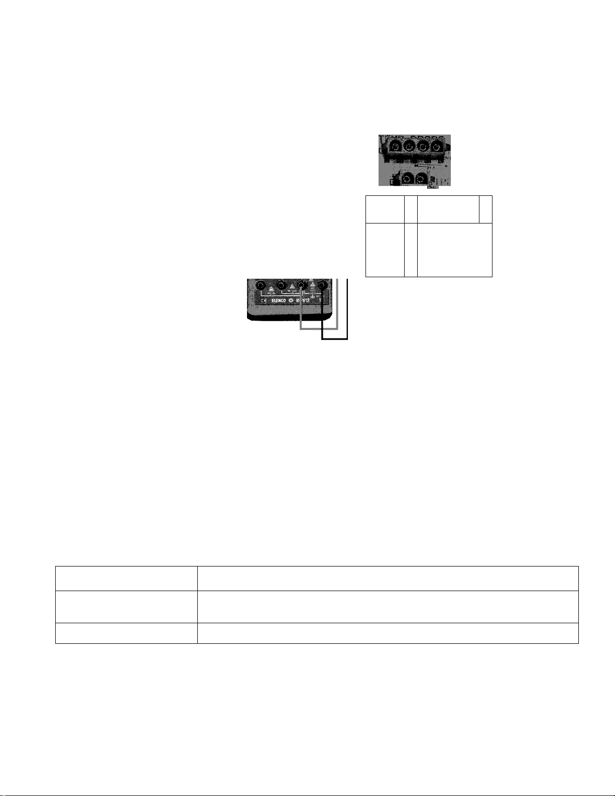
GAS VALVE TEST
STEP 12
24 VAC TO GAS VALVE
STEP 12: CHECK FOR 24 VAC TO GAS VALVE DURING TRIAL FOR IGNITION.
Condition:
• All wires are reconnected.
• On/Off switch is on.
• Call for heat is activated.
• Perform test at end of ignitor warm up period.
Touch meter probes to wiring terminals on gas valve with wires from control board still connected
during the ignitor warm up period.
IF... AND THEN
24 VAC is not present to gas valve
24 VAC is present gas does not flow to burner check for/restore supply gas;
24 VAC is present
gas does flow to burner continue to Step 13.
replace control board if Step 9A and 9B have
been performed and results were successful.
check for/clear any restriction in the gas train;
replace the gas valve if the valve will not open
with 24 VAC applied.
Technical Training Department
TC-044 Revision 6 32
A. O. Smith Water Products Co.
Ashland City, Tennessee © 2004
Page 34

BTH SERVICE HANDBOOK
TROUBLESHOOTING
GAS PRESSURE CHECK
Attach manometer or gas pressure gauge to pressure tap on gas valve or use adapter to check
pressure ahead of valve as near as possible to valve. All appliances being served by this gas sup
ply line should be operating.
IF... THEN
supply gas pressure is not between 5.0 and 14” W.C.
natural gas or 11.0 and 14” W.C. propane
proper supply gas pressure is present continue to Step 14.
adjust supply gas pressure (Recommended supply
minimum is 7.0” W.C. for natural gas models)
STEP 14 MANIFOLD GAS PRESSURE TEST
STEP 14: CHECK AND ADJUST MANIFOLD GAS PRESSURE.
IF... THEN
manifold gas pressure is not:
natural gas models
3.5” W.C. ± 0.3” - BTH 155 & 199
4.0” W.C. ± 0.3” - BTH 120 & 250
propane gas models
10.0” W.C. ± 0.3” - all propane gas models.
manifold gas pressure is within tolerances given above ignition should occur.
adjust manifold gas pressure to values given for model
and fuel type (within 0.3” W.C. tolerance)
if manifold gas pressure cannot be adjusted to
maintain values given (within 0.3” W.C. tolerance)
replace gas valve.
A. O. Smith Water Products Co.
Ashland City, Tennessee © 2004 33
Technical Training Department
TC-044 Revision 6
Page 35

BTH SERVICE HANDBOOK
COMPONENT INFORMATION
COMPONENT INFORMATION
FLAME SENSING ROD
AOS PART NUMBER FLAME SENSING CURRENT COMMENTS
192478
HOT SURFACE IGNITOR (HSI)
AOS PART NUMBER VOLTAGE AMP OHMS COLD COMMENTS
192638 120 VAC 1.0 50 - 300 BTH 120-250
0.7 Micro Amp (p)
BTH 120-250
ORIFICE TABLE
ORIFICE TABLE
BTH MODEL
120 192477-3
150 192477-1 0.235 192450-1 0.875
199 192477-0 0.304 192450-0 1.031
250
120 Prop 192477-6 0.125” 192450-5** 0.872
150 Prop 192477-5 0.141” 192450-5** 0.872
MAIN BURNER
ORIFICE NO.
192477-2
MAIN ORIFICE SIZE
INCHES
0.204
0.360
AIR ORIFICES
PT. NO.
192450-3 0.788
192450-2
AIR ORIFICE
SIZE — INCHES
1.196
199 Prop
192477-4
0.166”
192450-4**
*-4 and -5 Red plated for Propane.
** -4 and -5 stamped with “P” for Propane
NOTE: Hex head of main burner orifice is upstream end — gas flows out of tapered end.
1.150
Technical Training Department
TC-044 Revision 6 34
A. O. Smith Water Products Co.
Ashiand City, Tennessee © 2004
Page 36

Notes:
Low Gas Pressure Switch
(BTH 120 a 250 only)
is installed on the inlet
side of the Gas Valve.
N.O. = Normally Open
N.C. = Normally Closed
Blocked Inlet Switch
N. C. Contacts
BTH SERVICE HANDBOOK
COMPONENT NFORMATION
PRESSURE SWTCHES
PRESSURE SWITCH LAYOUT PRESSURE SWITCH WIRING
LOW GAS
Blower
PRESSURE
BTH 120 & 250
(normally open)
.BLOCKED
I OUTLET(FLUE)
(normally closed)
BLOWER
PROVER
(normally open)
.BLOCKED
I INLET
(normally closed)
Blower Prover Switch
N. 0. Contacts
Blocked Outlet Switch
N. C. Contacts
AA AA
CN6 Plug
Control Board
GAS VALVE
ILow Gas Pressure Switch
A. O. Smith Water Products Co.
Ashland City, Tennessee © 2004 35
Technical Training Department
TC-044 Revision 6
Page 37

BTH SERVICE HANDBOOK
COMPONENT INFORMATION
PRESSURE SWITCHES (CONTINUED)
PRESSURE SWITCHES
PART NUMBER / ACTIVATION PRESSURE^
Model Series Blocked Inlet
Normally Closed
Opens on a fall
Blower Prover
Normally Open
Closes on a rise
Low Gas Pressure
Normaily Open
Cioses on a rise
Biocked Outiet
Normaliy Ciosed
Opens on a rise
BTH 120 966 193293-000/-1.00” 193295-000/+0.45” 191149-001 /+5.00” 193294-000/+2.00”
967
193356-000/-2.00” 193295-000/+0.45” 191149-004/+9.00” 193357-000/+4.00”
970 193293-000/-1.00” 194706-000/+1.00” 191149-005/+5.20” 193294-000/+2.00”
971 193356-000/-2.00” 194706-000/+1.00” 191149-004/+9.00” 193357-000/+4.00”
973 193356-000/-2.00” 194706-000/+1.00” 191149-004/+9.00” 193357-000/+4.00”
BTH 150 960 N/A 192811-000/+4.20” N/A 192810-000/+4.35”
962 192882-000/-0.75” 193221-000/+0.45” N/A 192878-000/+2.53”
966 193363-000/-0.76” 193295-000/+0.45”
N/A
193362-000/+2.60”
967 193355-000/-1.80” 193295-000/+0.45” N/A 193357-000/+4.00”
970 193363-000/-0.76” 194706-000/+1.00” N/A 193362-000/+2.60”
971
193355-000/-1.80” 194706-000/+1.00”
N/A
193357-000/+4.00”
973 193355-000/-1.80” 194706-000/+1.00” N/A 193357-000/+4.00”
BTH 199 960 N/A 192811-000/+4.20” N/A 192810-000/+4.35”
962
192882-000/-0.75” 193221-000/+0.45”
N/A
192878-000/+2.53”
966 193363-000/-0.76” 193295-000/+0.45” N/A 193364-000/+2.87”
967 193356-000/-2.00” 193295-000/+0.45” N/A 193357-000/+4.00”
970 193363-000/-0.76” 194706-000/+1.00”
N/A 193364-000/+2.87”
971 193356-000/-2.00” 194706-000/+1.00” N/A 193357-000/+4.00”
973 193356-000/-2.00” 194706-000/+1.00” N/A 193357-000/+4.00”
BTH 250 962 192947-000/-0.77”
193221-000/+0.45” 193222-000/+4.75” 192946-000/+4.16”
966 193361-000/-0.77” 193295-000/+0.45” 191149-001 /+5.00” 193357-000/+4.00”
970 193361-000/-0.77” 194706-000/+1.00” 191149-005/+5.20” 193357-000/+4.00”
t- Pressure values are given in inches of water column pressure (“W.C.).
Negative pressure values in this table are preceded by a minus sign and indicate pressure below
atmospheric: in a vacuum. Positive pressures are preceded by a “+” plus sign and indicate pressure above
atmospheric.
Technical Training Department
TC-044 Revision 6
36
A. O. Smith Water Products Co.
Ashiand City, Tennessee © 2004
Page 38

BTH SERVICE HANDBOOK
WIRING DIAGRAMS
WIRING DIAGRAMS
BTH 120 -199/ ALL SERIES
BTH 250 / 970 SERIES
(without blower speed reduction)
A. O. Smith Water Products Co.
Ashland City, Tennessee © 2004
DETAIL BTH 250
962 & 966 SERIES ONLY
(with blower speed reduction)
37
Technical Training Department
TC-044 Revision 6
Page 39

BTH SERVICE HANDBOOK
SERVICE AIDS
SERVICE AIDS
1. This type product is polarity sensitive. Be certain that your eiectricai suppiy wire neutrai has
no voitage.
2. This unit wiii produce condensation — quite heaviiy at times. The outiet drain hose must be
allowed to drain. Exhaust Vent piping must aiso drain condensate. Code 11 error wouid impiy
that these must be checked.
3. if the unit is iocated in a coid ciimate, take steps to ensure that exhaust vapors are not puiied
into the air intake. Terminate both pipes on direct vent instaiiations in the same area, but max
imize the distance between them.
4. Do not combine vent these units.
5. Pushing the reset button at random times may aiter setting of the controi. Note the sequence of
operation comments on when to push this button.
6. if you make a setting change, cycle the heater with this new setting to iock it into memory.
7. The first items to check on a service caii
a. Correct venting instaiiation
b. Drainage of condensate from hose and exhaust vent pipe
8. BTH modeis are certified to 6.800 ft. above sea ievei with the standard orifice — air and gas.
9. The temperature dispiay board indicates average tank water temperature, if one tank sensor is
“open”, the indicator wiii dispiay the active sensor temperature. (Because the top tank sensor
aiso contains the high iimit-24V-sensor, disconnecting this from the controi board resuits in an
error code (04).)
10. Temperature and pressure reiief vaive operation. Weeping usuaiiy indicates thermai expan
sion. Large volume discharge usuaiiy indicates excessiveiy hot water operation.
11. BTH modeis are weii within decimai ievei iimits, but if you desire to iowerthe instaiiation ievei
approximateiy 6 decibeis a muffier (AOS No. 195334) may be instaiied in the exhaust vent.
Technical Training Department
TC-044 Revision 6
38
A. O. Smith Water Products Co.
Ashiand City, Tennessee © 2004
Page 40

BTH SERVICE HANDBOOK
SERVICE AIDS
BTH MUFFLER
u
, 4” X 3” PVC
REDUCING
COUPLING
I
4” PVC
(BOTH ENDS) \fii
SUPPORT
(FIELD SUPPLIED)
4” X 4” PVC
COUPLING
II
8 5/8”
3” PVC
VENTING
II
4” X 3” PVC
REDUCING
COUPLING
(FIELD SUPPLIED)
HEATER CONDENSATE
ELBOW
57 1/4"
4” X 4” PVC .
COUPLING
NG
(FIELD SUPPLIED)
iUPPLIED)
_j^
NOTES:
1. Install muffler in vertical position only.
2. Muffler must be a minimum of 8” from top of condensate elbow.
3. The muffler inlet and outlet are 4” PVC. If venting with a 4” PVC, a 4” x 4” PVC coupling (field
supplied) must be cemented to each end of the muffler. If venting with 3” PVC, a 4” x 3” PVC
reducing coupling (field supplied) must be cemented to each end of muffler (see illustration
above.)
4” PVC
VENTING
I__I
4. Cement muffler into a location using ASTM D-2564 grade cement.
5. Secure muffler to suitable structure.
6. Operate heater through 1 heat cycle to ensure there are no exhaust leaks and there is no
obstruction of exhaust flow.
A. O. Smith Water Products Co.
Ashland City, Tennessee © 2004 39
Technical Training Department
TC-044 Revision 6
Page 41

BTH SERVICE HANDBOOK
QUESTIONS AND ANSWERS
QUESTIONS AND ANSWERS
Q. How much electrical power is required for a BTH water heater?
A. The BTH models draw approximately 5.0 Amps Max.
Q. When should BTH’s be delimed?
A. Many variables affect the lime build up process including:
• Water temperature — the amount of lime accumulation during the same period of time will be
nearly 2 times great if water is stored at 140 degrees F than at 120 degrees F. A 180° setting
may accumulate seven times more lime — in a period of time — than at 140° setting.
• Volume of water— the more gallons flowing through the BTH, the more rapid the
accumulation.
• Hardness — the harder the water the quicker lime build up occurs. 1 to 3.5 grains per gallons
is “soft”, 3.5 to 7 grains per gallon is “moderate”, 7 to 10.5 grains per gallons is “hard” and
10.5+ grains per gallon is “very hard”. (An aspirin is about 5 grains. One grain is equal to 17.1
parts per million.)
A. Deliming should be done when a slight rumbling or popping sound is detected when the main
burner is on. Check for accumulation through the clean-out opening.
Q. What effect will lime build-up have on the BTH water heater?
A. One eighth inch of scale buildup on the heat exchanger may reduce efficiency as much as
22%: a % inch buildup, as much as 38%.
Less efficient heat transfer means more heat exchanger expansion/contraction stress and pre
mature leakage.
Because the heat transfer to the water is made through a (relatively) small diameter, coil type
exchanger tube, expansion and contraction as well as the shape of the exchanger greatly
reduces buildup on the heat transfer surface. The bottom of the tank should be checked for
dislodged accumulation.
Q. Anode rods (4) provide additional protection against corrosion. When should these be
replaced?
A. When large gauges or pits appear in the anodes, replace them.
Q. How often should the anodes be inspected?
A. Approximately every six months.
Technical Training Department
TC-044 Revision 6
40
A. O. Smith Water Products Co.
Ashland City, Tennessee © 2004
Page 42

BTH SERVICE HANDBOOK
ERROR CODES
ERROR CODES
CODE INDICATION
00 This is normal operation, 00 is displayed each time the heater is powered up.
Indicates the pressure switch circuit was not open during the prediagnostic system
check when the proper state of the Draft Prover Switches are verified. The Blower
Prover Switch is normally open, the circuit should therefore be open during the
01
prediagnostic system check at the beginning of each cycle. Check Blower Proving
Switch for continuity with the blower off, there should be no continuity, check
pressure switch wiring.
Indicates the heater faiied to light after 3 trials. Check ignitor, gas pressure, blower
02
speed reduction on BTH 250.
Indicates the ECO is open. Check water temperature in tank, ECO will open at 202°
04
F and can be reset below 160° F.
Indicates a Temperature Probe is open. Check both probes for proper resistance
05
and continuity.
Indicates the Pressure Switch Circuit did not close after blower was energized.
Check normally open Blower Prover Switch operation, check normally closed
11
Blocked Outlet, Inlet, and Low Gas pressure (BTH 120 and 250 only) to ensure they
remain closed. Check for blocked vent pipe (s) or if equivalent feet venting limits have
been exceeded.
15
22
25
CODE #S
ABOVE
199
Indicates temperature sensed by probe(s) is out of bounds, reading is less than
30° F. Check resistance of temp probes, check water temperature in tank.
Indicates Ignition Reiay faiiure. Should be off and it is on. Try resetting, turn power
off and on, if code remains, replace board.
Indicates temperature sensed by probe(s) is out of bounds. Reading is more than
220° F. Check resistance of temp probes, check water temperature.
Internai software or hardware errors, electrical line noise can cause erratic
operation and these error codes. Try adding a “line fiiter” (available from electrical
suppliers) to the 120 VAC power supply. If these errors codes persist or the control
cannot be reset, replace the control board.
All these errors cause a “soft” lockout with the exception of 04 ECO, which is a “hard” lockout. Soft lockouts will reset automati
cally after 60 minutes or if the reset button is pushed at any time.
The ECO lockout, error code 04 will have to be manually reset by
pushing the rest button after water in the tank has cooled below
160° F.
A. O. Smith Water Products Co.
Ashland City, Tennessee © 2004
41
Technical Training Department
TC-044 Revision 6
Page 43

BTH SERVICE HANDBOOK
SERVICE CHECKLIST
SERVICE CHECKLIST
This is not intended to be and all-inclusive list of the problem that the Service Agent may encounter. Any item checked “no” on
this list should be thoroughly investigated and corrective action taken, if required.
SERVICE AGENT:
MODEL NUMBER:
SERIAL NUMBER:
GAS
CHECK CLEARANCE (CIRCLE ANSWER)
TYPE —CHECK ONE
NATURAL
PROPANE
PROPER GAS VALUE VERIFIED
A. Are exterior clearances adequate?
B. Are interior clearances adequate?
Comments:
CHECK MAKEUP AIR REQUIREMENTS
A. Is the quality of make-up air adequate?
Comments:
--------------YES
INSTALLATION DATE:
SERVICE DATE:
LOCATION ADDRESS:
PHONE ( )
NO
yes
yes
yes
no
no
no
B. Is the quantity of make-up air adequate?
Comments:
GAS PRESSURE (FILL IN BLANK) — ALL UNITS ON.
A. Supply gas pressure_inches of W.C. (flowing)
B. Manifold gas pressure (main burner)_inches of W.C. (flowing)
Comments:
IV.
VENTING (CHECK)
A. Acceptable equivalent footage
B. Proper material
C. Proper exterior installation
D. Condensate will drain
Comments:
V. WATER PIPING
Is the system properly sized?
Is the system properly installed?
Are there any water leaks?
Does the installation have a recirculating system?
If so, is it operational?
SAFETYVI.
A. Air
If exhaust is blocked will unit lockout?
If air intake is blocked will unit lockout?
B.
Water Temperature
- Is the thermostat adjusted to the lowest acceptable temperature?
- Does the installation have a mixing valve?
- If so, is it operational?
- What is the outlet temperature of the mixing valve?
NOTE: To minimize the risk of scalding, the manufacturer recommends storing water at 120° F.
Is a properly rated temperature and pressure relief valve installed?
Is there a properly installed expansion tank?
Should there be?
C. Electrical
Is the 120 VAC electrical powers supply properly wired? (including polarity)
Are all the BTH control covers in place?
Is the 120 VAC electrical power supply properly fused?
D. Flammables
Are flammable materials located in the area of the water heater? or air intake?
Are flammable vapors located in the area of the water heater? or air intake?
E. Gas
If the gas supply is reduced or turned off will the unit turn off?
Comments:
yes no
yes
yes
yes
yes
yes
yes
yes
yes
yes
yes
yes
yes
yes
yes
yes
yes
yes
yes
yes
yes
yes
yes
yes
yes
no
no
no
no
no
no
no
no
no
no
no
no
no
no
no
no
no
no
no
no
no
no
no
no
[This service checklist may be photo copied to assist with BTH service calls.]
Technical Training Department
TC-044 Revision 6 42
A. O. Smith Water Products Co.
Ashiand City, Tennessee © 2004
Page 44

ВТН SERVICE HANDBOOK
PARTS LISTS
/дЛ,, c 1ТТГ^ I
WATER PRODUCTS
COIVIPAM Y
COMMERCIAL WATER HEATER PARTS LIST
MODEL BTH -120, 150,199,250
SERIES 970 & 973
Page 45

BTH SERVICE HANDBOOK
PARTS LISTS
BTH 1200-250
EXHAUST ELBOW & VENT
KIT FARTS
'%■ <>.. ■
63-^-N^ 62
n
60 I
181617
LI
192815 182167
61
\
( >1
63
65
CLEANOUT ASSEMBLY
2
Technical Training Department
TC-044 Revision 6 44
CONTROL PANEL
17a
A. O. Smith Water Products Co.
Ashiand City, Tennessee © 2004
Page 46

BTH SERVICE HANDBOOK
BURNER ASSEMBO^
PARTS LISTS
GAS VALVE
75 70
f h
"t '
69
A. O. Smith Water Products Co.
Ashland City, Tennessee © 2004 45
Technical Training Department
TC-044 Revision 6
Page 47

BTH s E R V 1 C E HAN D B 0 0 K
p
ARTS
LISTS
DESCRIPTION
#
BTH 120
970
BTH 120
973
BTH 150
970
BTH 150
973
BTH 199
970
BTH 199
973
BTH 250
970
1 Cleanout Cover If? 1260 181260 181260 181260 181260 181260 181260
2
Cleanout Gasket 99038 99038 99038 99038 99038 99038 99038
3 Cleanout Plato
4
Top Cover. Left 193885 193885 193885 193885 193885 193885 193885
99037 99037 99037 99037 99037 99037 99037
5 Top Cover, Right 193886 193886 193886 193886 193886 193886 193886
6 Top Cover, Back, Nat.
Top Cover. Back. Prop. 193887 193887 193887 193887 193887 193887
6
193887 193887 193887 193887 193887 193887 193887
7 Drain Valve 26273-6 26273-6 26273-6 26273-6 26273-6 26273-6 26273-6
8 T & P Roliel Valve 99465-7 99465-7 99465-7 99465-7 99465-7 99465-7 192467
9 Upper Temp. Probe w/ECO 192606 192606 192606 192606 192606 192606
192606
10 Lower Temp. Probe 192609 192609 192609 192609 192609 192609 192609
11
Anode, Alum. Alloy (4)
13 ii Manual*
:yclone xhe bth — control
14
Board, Display Panel
17
Control Board & Cable
183523-33 183523-52 183523-52 183523-52 183523-52 183523-52 183523-52
196145
196145 196145 196145 196145 196145 196145
PANEL
192622-1 192622-1 192622-1 192622-1 192622-1 192622-1 192622-1
193822 193822 193822 193822 193822 193822 193822
Assem. (includes 17a)
17a
Cable Assem., Control Board
192623 192623 192623 192623 192623 192623 192623
to Display Board
20 Display Panel Label 194203 194203 194203 194203 194203 191203 194203
21
Panel, rronl 193884
193884 193884 193884 193884 193884 193884
23 On/Off Switch 193243 193243 193243 193243 193243 193243 193243
24 Cablo Assembly. Lino Power 19-1261
194261 194261 194261 194261 194261 194261
BTH 120 - 250 TOP COVER CONTROLS
25 Blocked Inlet Switch, Natural
193293 193363 193363 193361
Gas
25 Blocked Inlet Switch, Propane
193356 193355
195012
Gas
26 Blocked Outlet Switch, Natu
193294 193362 193364 193357
ral Gas
26 Blocked Outlet Switch, Pro
193357
193357
193357
pane Gas
27 Blower Prover Switch
194706 194706 194706 194706
28 Blower/Motor Assembly 194675 194675 194673 194675 194673 194675
29 Inlet Flange Assembly w/
192886-1 192886-1 192886-1 192886-1 192886-1 192886-1 192886-1
194706 194706
194706
194674
Hose Barb
30 Intake Assembly 192815 192815 192815 192815 192815 192815 194116
34 Cable Assembly, Low Voltage 193246 193246 193246 193246 193246 193246 193246
35 Wire Assembly, Air Flow
192802 192802 192802 192802 192802 192802 192802
36 Bracket, Blower Mounting 192482 192482 192482 192482 192482 192482 192482
37
Tube, Pressure 193738-8 193738-8 193738-8 193738-8 193738-8 193738-8 193738-8
38 Tube, Pressure 193738-22 193738-22 193738-22 193738-22 193738-22 193738-22 193738-22
41
Tube, Air 192469-10 192469-10 192469-10 192469-10 192469-10 192469-10 192469-10
43 Transformer, 120V-24V,60
192608 192608 192608 192608 192608 192608 192608
Hz,20 VA
Technical Training Department
TC-044 Revision 6
46
A. O. Smith Water Products Co.
Ashland City, Tennessee © 2004
Page 48

B T H s E R V 1 C E HAN D B 0 0 K
p
ARTS LISTS
rvCer'DIDXir^M
a
BTH 120 BTH 120 BTH 150 BTH 150 BTH 199 BTH 199 BTH 250
970 973
970 973 970 973 970
44 li Wire Assembly, Air Flow 192802-1 192802-1 192802-1
1 Switch
GAS VALVE
48 1 Switch, Low Gas Pressure,
191149-5
191149-5
Natural
48
191149-4
Propane
50 Gas Valve. Natural Gas 192966
50 1 Gas Valve, Propane Gas
192967
192797 192797 192454
192454-1
192454-1
EXHAUST ELBOW, VENT KIT PARTS
51 1 Adapter, Hose Fitting 192472 192472 192472 192472 192472 192472 192472
52 Elbow 90
192473 192473 192473 192473 192473 192473 192473
53 1 Nipple, Close 194558 194558 194558 194558 194558 194558 194558
54
Plug, Hex
194560 194560 194560 194560 194560 194560 194560
55 1 Tee 194559 194559 194559 194559 194559 194559 194559
56 Tubing 191746-72 191746-72 191746-72 191746-72 191746-72 191746-72 191746-72
57
1 Connector, Exhaust 192636 192636 192636 192636 192636 192636 192636
VENT KIT PARTS
60 1 Elbow w/Screen 192815 192815 192815 192815 192815 192815 192815
61 Elbow. 45 X 3.5" 181901 181901 181901 181901 181901 181901 181901
62 1 Screen 181662 181662 181662 181662 181662 181662 181662
63 1 Intake Vent Terminal Assy. 182167 182167 181617 181617 181617
64 ii Wall Plates (2 Req’d.) 181557 1815' ■ 181557 181557 181557 181557 181557
65 1 Silicone Sealer, 2 oz. Tube
181564
1815t
181564 181564 181564 181564 181564
BURNER — ASSEMBLY
Burner
66
Burner for (BTH - 120, 150,
66
II
196162 19611 196ie 196K
196162-1
1 196162-1
196162-1
*1991973
67
Ignitor Assembly 192638 192638
69 Air Restrictor — Natural Gas 192450-3 192450-1 192450
192638
192638
192638 192638 192638
192450-2
69 1 Air Restrictor — Propane Gas i 192450-5 192450-5 192450
70 1 1 lose Barb 192800-1 192800-1 192800-1 192800-1 192800-1 192800-1 192800-1
71 1 Flame Rod Assembly 192478 192478 192478 192478 192478 192478 192478
73 Orifice — Natural Gas 192477-3
192477-1 192477 192477-2
73 Orifice — Propane Gas 192477-6 192477-5 192477-10
74
Orifice Holder
192447 192447 192447 192447 192447 192447 192447
75 Gasket 192331 192331 192331 192331 192331 192331 192331
76 5/16” X 7/8" Socket Head Cap
192515-2
192515-2 192515-2
1 192515-2
192515-2 192515-2
192515-2
Screw (4 Req’d.)
*Not illustrated.
NOTE: Shaded parts are recommended stock items for emergency replacement. Consider gas used in
your area only. Standard hardware items may be purchased locally.
A. O. Smith Water Products Co.
Ashland City, Tennessee © 2004
47
Technical Training Department
TC-044 Revision 6
Page 49

Z^o SEfflDUE]
ВТН SERVICE HANDBOOK
PARTS LISTS
WATER PRODUCTS
COMPANY
COMMERCIAL WATER HEATER PARTS LIST
CYCLONE XHE MODEL BTH -120
SERIES 966/967
(PARTIAL PARTS LISTING)
33
Technical Training Department
TC-044 Revision 6
A. O. SMITH WATER PRODUCTS CO.,INC.
PARTS INFORMATION
PHONE: 1-800-433-2545
FAX: 1-800-433-2515 -WWW.AOSMITHWATERHEATERS.COM
48
A. O. Smith Water Products Co.
Ashland City, Tennessee © 2004
Page 50

ВТН SERVICE HANDBOOK
PARTS STS
CYCLONE XHE® MODEL
BTH -120 WATER HEATER PARTS LIST (PARTIAL)
SERIES 966/967
ITEM DESCRIPTION BTH -120
1
ii Anode 043817-029
2 ii Panel, Front 193884-000
5 Panol. Loft Sido 193885-000
6 Panol. Right Sido 193888-000
20 Condonsalo I loso 181864-072
22 Barb. Hose
24 Exhaust Torminal 192815-000
25 II Intake Terminal 192815-000
27 II Plate, Pressure 099037-000
28 Gasket 099038-000
29 I Valve, Relief 192467-000
30 Clamp. I loso. Nylon Snap 191794-001
33 II Panel, Back 193887-000
36 ii Instruction Manual 194119-000
181863-000
A. O. Smith Water Products Co.
Ashland City, Tennessee © 2004 49
Technical Training Department
TC-044 Revision 6
Page 51

ВТН SERVICE HANDBOOK
PARTS LISTS
CYCLONE XHE® MODEL
BTH -120 CONTROLS PART LIST — SERIES 966/967
966 = NATURAL GAS
967 = PROPANE GAS
ITEM DESCRIPTION
1
I Transformer 192608-001
BTH-120
2 1 Control Board 193822-000
3 E.C.O. Tomporaluro Probo 192606-000
4 Blower Proving Air Switch 193295-000
7
Blower Assembly
193341-000
8 Igniter Assembly 192638-000
9 I Cable to Control Display Board 192623-000
10 Board. Display Panel 192622-001
11 Blocked Outlet Proving Switch 193294-000
12
Temperature Probe, Lower 192609-000
14
1 Tubing, Pressure
192024-002
15 I Tubing, Pressure 192024-006
16 I Tubing, Connector 192152-000
17 Swilch-On.^Olf 193243-000
18 I Low Nat. Gas Pressure Switch 191149-001
19 I Low Prop. Gas Pressure Switch 191149-004
20 Blocked Inlot Switch 193293-000
Part numbers in shaded cells are recommend stock items for emer
gency replacement.
Technical Training Department
TC-044 Revision 6
50
A. O. Smith Water Products Co.
Ashiand City, Tennessee © 2004
Page 52

ВТН SERVICE HANDBOOK
PARTS LISTS
CYCLONE XHE® MODEL
BTH -120 BURNER & BLOWER PARTS LIST — SERIES 966/967
15
ITEM DESCRIPTION BTH-120
1
Nat Burner 194114-003
1 Prop Burner
2
Ignitor Assembly 192638-000
194114-006
6 Barb. I lose. 3. IK" 181863-000
7 Flame Rod Assembly
192478-000
9 Nat Orifice 192477-003
9 Prop Orifice 192477-006
13 Valve. Nat Gas 192966-000
13 Valve. Prop Gas 192967-000
14
II Blower 193341-000
15 Tubo. Air 192469-010
18 Flange Assembly. Inlet 192886-001
19 Low Nat. Gas Pressure Switch 191149-001
19 Low Prop. Gas Pressure Switch 191149-004
Part numbers in shaded cells are recommended stock items for emer
gency replacement.
A. O. Smith Water Products Co.
Ashland City, Tennessee © 2004 51
Technical Training Department
TC-044 Revision 6
Page 53

ВТН SERVICE HANDBOOK
PARTS LISTS
WATER PRODUCTS
COMPANY
COMMERCIAL WATER HEATER PARTS LIST
CYCLONE XHE MODEL BTH -150, BTH -199
SERIES 966 & 967
(PARTIAL PARTS LISTING)
24
EXHAUST TERMINAL
DIRECT VENT INTAKE TEE
Technical Training Department
TC-044 Revision 6
A. O. SMITH WATER PRODUCTS CO.,INC.
PARTS INFORMATION
PHONE; 1-800-433-2545
FAX: 1-800-433-2515 • WWW.AOSMITHWATERHEATERS.COM
52
CLEANOUT ASSEMBLY
A. O. Smith Water Products Co.
Ashland City, Tennessee © 2004
Page 54

ВТН SERVICE HANDBOOK
PARTS STS
CYCLONE XHE® MODELS
BTH -150 & BTH -199 SERIES 966 & 967
CONTROLS PARTS LIST (PARTIAL)
ITEM DESCRIPTION
1 Anode
2
Panel, rrent 194884-000 194884-000 194884-000 194884-000
BTH -150
NATURAL
(966)
0435517-053
PROPANE
(967)
043817-053
BTH -199
NATURAL
(966)
043817-053
PROPANE
(967)
043817-053
3 Burner Assembly 194114-001 194114-005 194114-000 194114-004
4 Blower
193354-000 193354-000 193354-000 193354-000
5 Panel. Loft Side 193885-000 193885-000 193885-000 193885-000
6 Panel. Right Side 193886-000 193886-000 193886-000 193886-000
19 Valve. Drain 026273-004 026273-001
026273-004 026273-004
20 Condensate I lose 191746-072 181894-072 191746-072 181894-072
22
Barb. Hose 181863-000 181863-000 181863-000 181863-000
24 Exhaust Terminal 192815-000 192815-000 192815-000 192815-000
25 Direct Vent Kit 193202-000 193202-000 193202-000 193202-000
27
Plate, Pressure 099037-000 099037000 099037-000 099037-000
28 Gasket 099038-000 099038-000 099038-000 099038-000
29 Valve. Relief 192467-000 192467-000 192467-000 192467-000
33‘ Screen. Exhaust 181662-000 181662-000 181662-000 181662-000
34
Panel. Back 193887-000 193887-000 193887-000 193887-000
37
Gasket 192331-000 192331-000 192331-000 192331-000
*Not Illustrated
A. O. Smith Water Products Co.
Ashland City, Tennessee © 2004 53
Technical Training Department
TC-044 Revision 6
Page 55

ВТН SERVICE HANDBOOK
PARTS STS
CYCLONE XHE® MODELS
BTH -150 & BTH -199 SERIES 966 & 967 CONTROLS PARTS LIST
BTH -150 BTH - 199
ITEM DESCRIPTION
NATURAL PROPANE NATURAL PROPANE
(966) (967) (966) (967)
1 I Transformer 192K0f?-001 192608-001 192608-001 192608-001
2
Control Board 193822-000 193822-000 193822-000 193822-000
3 E.C.O.. Upper Probe 192Й0Й-000 192606-000 192606-000 192606-000
4
Blower Proving Switch 193295-000 193295-000 193295-000 193295-000
7 I Blower Assembly 192880-000 192880-000 192880-000 192880-000
8 Ignitor Assembly 192638-000 192638-000 192638-000 192638-000
9 Cable to Control Display Board 192623-001 192623-000 192623-000 192623-000
10 I Board, Display Panel 192622-001 192622-001 192622-001 192622-001
11
I Blocked Outlet Switch 193362-000 193357-000 193364-000 193357-000
12 Tomperatiiro Probe. Lower 192609-000 192609-000 192609-000 192609-000
14
Tubing. Pressure 192024-006 192024-0006 192024-006 192024-006
15 Tubing. Pressure 192024-004 192024-004 192024-004 192024-004
16 Connector. Tubo 192152-000 192152-000 192152-000 192152-000
17
I Blocked Inlet Switch 193363-000 193355-000 193363-000 193356-000
18 ON.-OFF Switch 193243-000 193234-000
Technical Training Department
TC-044 Revision 6 54
193234-000
193234-000
A. O. Smith Water Products Co.
Ashland City, Tennessee © 2004
Page 56

ВТН SERVICE HANDBOOK
PARTS STS
CYCLONE XHE® MODELS
BTH -150 & BTH -199 SERIES 966 & 967 BURNER & BLOWER PARTS LIST
BTH-150 BTH-199
ITEM DESCRIPTION NATURAL
(966)
1
I Burner Assembly 1941И-001 194114-005 194114-000
PROPANE NATURAL PROPANE
(967)
(966)
(967)
194114-004
2 Ignitor Assembly 192e3f?-000 192638-000 192638-000 192638-000
7
Flame Rod Assembly 192478-000 192478-000 192478-000 192478-000
9 Ori rice 192477-001 192477-005 192477-000
192477-004
13 Valve, Gas 192797-000 192454-001 192797-000 192454-001
14
Blower 193354-000 193354-000 193354-000 11 193354-000
15 Tubo. Air 1924Й9-010 192469-010 192469-010 192469-010
18 Flange. Inlet 192641-001 192886-001 192641-001 1192886-001
A. O. Smith Water Products Co.
Ashland City, Tennessee © 2004 55
Technical Training Department
TC-044 Revision 6
Page 57

ra. SKanTrra
BTH SERVICE H A N D B O O K
PARTS LISTS
WATER PRODUCTS
COMPANY
CYCLONE XHE^ MODEL BTH - 250
COMMERCIAL WATER HEATER PARTS LIST
SERIES 966
(PARTIAL PARTS LISTING)
Technical Training Department
TC-044 Revision 6
A. O. SMITH WATER PRODUCTS CO.,INC.
PARTS INFORMATION
PHONE: 1-800-433-2545
FAX; 1-800-433-2515 • WWW.AOSMITHWATERHEATERS.COM
56
A. O. Smith Water Products Co.
Ashiand City, Tennessee © 2004
Page 58

ВТН SERVICE HANDBOOK
PARTS LISTS
CYCLONE XHE® MODEL
BTH - 250 WATER HEATER PARTS LIST (PARTIAL)
SERIES 966
ITEM DESCRIPTION BTH - 250
1
Anode
2
Panel, Front 194884-000
3
Burner Assembly
4
Blower 193203-000
5 Panel, Left Side 193885-000
6 Panel, Right Side 193886-000
17
Temperature Probe, Lower 192609-000
19 Valve, Drain 026273-004
20 Condensate Hose 181894-072
22
Barb, Hose 181863-000
24
Exhaust Terminal 192815-000
25 Direct Vent Intake Terminal 181762-000
27 Plate, Pressure 099037-000
28 Gasket 099038-000
29
Valve, Relief 192467-000
33 Panel, Back 193887-000
043817-053
194114-002
Part numbers in shaded cells are recommended stock
items for emergency replacement.
A. O. Smith Water Products Co.
Ashland City, Tennessee © 2004 57
Technical Training Department
TC-044 Revision 6
Page 59

ВТН SERVICE HANDBOOK
PARTS STS
CYCLONE XHE® MODELS
BTH - 250 CONTROLS PARTS LIST — SERIES 966
ITEM DESCRIPTION BTH - 250
1 Transformer
192608-001
2 Control Board 193822-000
3 II E.C.O./Temperature Probe 192606-000
4 II Blower Proving Air Switch 193295-000
7
1 Blower Assembly 193203-000
8 Ignitor Assembly
192638-000
g Cable to Control Display Board 192623-000
10 II Board, Display Panel 192622-001
11 Bloeked Outlet Proving Switeh 193357-000
12
Temperature Probe. Lower 192609-000
14 Tubing. Pressure 192024-001
15 II Tubing, Pressure 192024-006
Tubing. Connector
16
192152-000
17 Blower Speed Redueing Panel 192987-000
18 Low Gas Pressure Switch 191149-001
19 Blocked Inlet Switeh 193361-000
21
Switch-On-Off 193243-000
Part numbers in shaded cells are recommended for
stock items for emergency replacement.
Technical Training Department
TC-044 Revision 6
58
A. O. Smith Water Products Co.
Ashiand City, Tennessee © 2004
Page 60

ВТН SERVICE HANDBOOK
PARTS LISTS
CYCLONE XHE® MODELS
BTH - 250 BURNER & BLOWER PARTS LIST — SERIES 966
ITEM DESCRIPTION BTH-250
1 Burnor 194114-002
2 Icjnitor Assembly 192638-000
7 Flame Rod Assombly 192478-000
9 Orifice 192477-002
13 Valve. Gas 192464-000
14 Blower 193203-000
15 Tube. Air 192469-010
18 Flange Assembly. Inlel 192886-001
19 .Low Gas Pressure Switch i 191149-001
Part numbers in shaded cells are recommended
for stock items for emergency replacement.
A. O. Smith Water Products Co.
Ashland City, Tennessee © 2004 59
Technical Training Department
TC-044 Revision 6
Page 61

ВТН SERVICE HANDBOOK
PARTS LISTS
ё^РХППТгГЯ
WATER PRODUCTS
COMPANY
CYCLONE XHE MODEL BTH -150, BTH-199
COMMERCIAL WATER HEATER PARTS LIST
SERIES 960
(PARTIAL PARTS LISTING)
24
EXHAUST TERMINAL
DIRECT VENT TERMINAL
Technical Training Department
TC-044 Revision 6
A. O. SMITH WATER PRODUCTS CO.,INC.
PARTS INFORMATION
PHONE; 1-800-433-2545
FAX: 1-800-433-2515 •WWW.AOSMITHWATERHEATERS.COM
60
CLEANOUT ASSEMBLY
A. O. Smith Water Products Co.
Ashiand City, Tennessee © 2004
Page 62

ВТН SERVICE HANDBOOK
PARTS LISTS
CYCLONE XHE® MODEL
BTH -150 & BTH -199 WATER HEATER PARTS LIST — SERIES 960
ITEM DESCRIPTION BTH -150 BTH -199
1 I
I Anode 043817-053 043817-053
2
I Cover, Jacket 192664-000 192664-000
3 I Burner Assembly 192417-001 192417-001
4 iI Motor, Blower
5 I Cage, Housing 192420-000 192420-000
6 I Bracket, Control Panel 192716-000 192716-000
17 II Temperature Probe, Lower 192609-000
20 I Condensate Hose 191746-072 191746-072
22
I Barb, Hose 181863-000 181863-000
24 I Exhaust Terminal 181901-000 181901-000
25 I Direct Vent Kit 182167-000 182167-000
27 I Plate, Pressure 099037-000 099037-000
28 I Gasket 099038-000 099038-000
29 I Valve, Relief 191617-000
192880-000 192880-000
192609-000
191617-000
A. O. Smith Water Products Co.
Ashland City, Tennessee © 2004 61
Technical Training Department
TC-044 Revision 6
Page 63

ВТН SERVICE HANDBOOK
PARTS STS
CYCLONE XHE® MODEL
BTH -150 & BTH -199 WATER HEATER PARTS LIST — SERIES 960
ITEM DESCRIPTION
BTH-150 BTH -199
1 II Transformer 19260t5-000 192508-000
2
Control Board 192624-000 192624-000
3 E.C.O..TomporaUiro Probo 192606-000 192506-000
4
Blower Proving Air Switch 192811-000 192811-000
5 Low Voltage Cable Assembly 192605-000 192805-000
6 Lino Voltage Cable Assembly 192607-000 192607-000
7
Blower Assembly 192468-000 192468-000
8
Igniter Assembly
192638-000 192538-000
9 Cable to Control Display Board 192623-000 192623-000
10 Board. Display Panol 192622-001 192522-001
11 Blocked riue Proving Switch
192810-000 192810-000
12 Temporature Probo. Lower 192609-000 192509-000
13 li Wire Assembly, Air Flow Switch 192802-000 192302-000
14
Tubing. Pressure 192024-014 192024-014
15A Tubing. Pressure 192024-004 192024-004
16A
Tubing. Pressure 192024-004
192024-004
17A Tubing. Pressure 192024-008 192024-008
18A
II Connector, Tube 192152-000 192152-000
19 II Tubing, Pressure 192024-008 192024-008
Technical Training Department
TC-044 Revision 6 62
A. O. Smith Water Products Co.
Ashland City, Tennessee © 2004
Page 64

ВТН SERVICE HANDBOOK
PARTS LISTS
CYCLONE XHE® MODEL
BTH -150 & BTH -199 BURNER & BLOWER PARTS LIST — SERIES 960
ITEM 1 DESCRIPTION
1 1 Burner
2
1 Igniter Assembly 192638-000 192638-000
BTH-150 BTH -199
192416-000
192416-000
4 1 Air Deflector 192414-000 192414-000
5 1 Air Restrictor 192450-001 192450-001
6 1 Barb, Hose, 3/16 ’ 192800-000 192800-000
7
1 Flame Rode Assembly 192478-000 192478-000
9 ^ Orifice 192477-001 192477-000
10
1 Orifice Holder 192447-000 192447-000
13 1 Valve, Gas 192797-000 192797-000
14 1 Blower
192468-000
192468-000
15 1 Tube, Air 192469-000 192469-000
17 1 Bracket, Blower Mounting 192482-000 192482-000
18
1 Flange Inlet 192641-000
192641-000
A. O. Smith Water Products Co.
Ashland City, Tennessee © 2004 63
Technical Training Department
TC-044 Revision 6
Page 65

ВТН SERVICE HANDBOOK
PARTS LISTS
аКЛПТгГЯ
WATER PRODUCTS
COMPANY
CYCLONE XHE® MODEL BTH - 250
COMMERCIAL WATER HEATER PARTS LIST
SERIES 962
(PARTIAL PARTS LISTING)
A. O. SMITH WATER PRODUCTS CO.,INC.
PARTS INFORMATION
PHONE: 1-800-433-2545
FAX: 1-800-433-2515 -WWW.AOSMITHWATERHEATERS.COM
Technical Training Department
TC-044 Revision 6 64
A. O. Smith Water Products Co.
Ashiand City, Tennessee © 2004
Page 66

ВТН SERVICE HANDBOOK
PARTS LISTS
CYCLONE XHE® MODEL
BTH - 250 WATER HEATER PARTS LIST (PARTIAL)
SERIES 962
ITEM DESCRIPTION BTH - 250
1
I Anode 043817-004
2
I Cover, Jacket 192664-000
3 I Burner Assembly 192417-003
4 I Motor, Blower
5 I Cage, Housing 192420-000
6 I Bracket, Control Panel 192716-000
17 I Temperature Probe, Lower 192609-000
20 I Condensate Hose 181864-000
22 I Barb, Hose 181863-000
24
Exhaust Vent Terminal 192815-000
25 I Direct Vent Intake Tee
27 I Plate, Pressure 099037-000
28 I Gasket 099038-000
29 I Valve, Relief
193203-000
181762-000
192467-000
Part numbers in shaded cells are recommended
stock items for emergency replacement.
A. O. Smith Water Products Co.
Ashland City, Tennessee © 2004 65
Technical Training Department
TC-044 Revision 6
Page 67

ВТН SERVICE HANDBOOK
PARTS STS
CYCLONE XHE® MODELS
BTH - 250 CONTROLS PARTS LIST — SERIES 962
Technical Training Department
TC-044 Revision 6
ITEM DESCRIPTION BTH - 250
1 Transformer 192K0f?-001
2
I Control Board 192624-000
3 E.C.O.-Tomporaluro Probe 192606-000
4 Blowor Proving Air Switch 193221-000
5 Low Voltage Cable Assembly 192605-000
6 Lino Voltage Cable Assembly 192607-000
7
Blower Assembly 193203-000
8 Igniter Assembly 192638-001
9 Cable to Control Display Board 192623-000
10 I Board, Display Panel 192622-000
11 I Blocked Outlet Proving Switch 192946-000
12
I Temperature Probe, Lower 192609-000
13 Wire Assembly. Air Flow Switch 192802-001
14
Tubing. Pressure
192024-002
15 Tubing. Pressure 192024-006
16 Tubing. Connector 192152-000
17
Blower Speed Reducing Panel 192987-000
18 Low Gas Pressure Switch 193222-001
19 I Blocked Inlet Switch 192947-000
20 Wire Assembly. Air Flow Switch 192802-000
21 Switch-On.'Olf 192699-000
66
A. O. Smith Water Products Co.
Ashland City, Tennessee © 2004
Page 68

ВТН SERVICE HANDBOOK
PARTS LISTS
CYCLONE XHE® MODELS
BTH - 250 BURNER & BLOWER PARTS LISTS — SERIES 962
17
ITEM 1 DESCRIPTION
1 1 Burner
2
1 Igniter Assembly
BTH-250
192416-000
192638-000
3 1 Rivet, Blind, 1/8” Dia 316 SS 192730-000
4 I Air Deflector
5 I Air Restrictor
192414-000
192450-002
6 I Barb, Hose, 3/16” 192800-000
7 1 Flame Rod Assembly
9 ^ Orifice
10
1 Orifice Holder 192447-000
192478-000
192477-002
13 1 Valve, Gas 192454-000
14 1 Blower 193203-000
15 1 Tube, Air
17
1 Bracket, Blower Mounting 192482-000
192469-010
18 1 Flange Assembly, Inlet 192886-000
19 1 Low Gas Pressure Switch 191149-001
Part numbers in shaded cells are recommended stock
items for emergency replacement.
A. O. Smith Water Products Co.
Ashland City, Tennessee © 2004
67
Technical Training Department
TC-044 Revision 6
Page 69

ВТН SERVICE HANDBOOK
PARTS LISTS
WATER PRODUCTS
COMPANY
/д
¿5?
COMMERCIAL WATER HEATER PARTS LIST
CYCLONE XHE MODEL BTH -150 & BTH -199
SERIES 962
(PARTIAL PARTS LISTING)
EXHAUST TERMINAL
DIRECT VENT TERMINAL
CLEANOUT ASSEMBLY
Technical Training Department
TC-044 Revision 6
A. O. SMITH WATER PRODUCTS CO.,INC.
PARTS INFORMATION
PHONE: 1-800-433-2545
FAX: 1-800-433-2515 -WWW.AOSMITHWATERHEATERS.COM
68
A. O. Smith Water Products Co.
Ashland City, Tennessee © 2004
Page 70

ВТН SERVICE HANDBOOK
PARTS STS
CYCLONE XHE® MODEL
BTH -150 & BTH -199 WATER HEATER PARTS LIST — SERIES 962
ITEM DESCRIPTION
1
li Anode 0-13817-053 0-13817-053
2 Cover. Jacket
BTH -150 BTH -199
192664-00 192664-000
3 li Burner Assembly 192417-001 192417-001
4 Motor. Blower
192880-000 192880-000
5 Cage. I lousing 192420-000 192420-000
6 I Bracket, Control Panel 192716-000 192716-000
17 Temperature Probe. Lower 192609-000 192609-000
20 Condensate I lose 191746-072 191746-072
22
Barb. Hose 181863-000 181863-000
24 I Exhaust Terminal 181901-000 181901-000
25 Direct Vent Kit 182167-000 182167-000
27 Plate. Pressure 099037-000 099037-000
28 I Gasket 099038-000 099038-000
29 Valve. Roliel
191617-000
191617-000
Part numbers in shaded cells are recommended stock items for emer
gency replacement.
A. O. Smith Water Products Co.
Ashland City, Tennessee © 2004 69
Technical Training Department
TC-044 Revision 6
Page 71

ВТН SERVICE HANDBOOK
PARTS LISTS
CYCLONE XHE® MODELS
BTH -150 & BTH -199 CONTROL PARTS LIST — SERIES 962
TO BLOWER
Technical Training Department
TC-044 Revision 6
ITEM DESCRIPTION BTH -150 BTH -199
1
1 Transformer 192608-000 192608-000
2 1 Control Board 192624-000 192624-000
3 E.C.O/Temperature Probe
192606-000
192606-000
4 1 Blower Proving Air Switch 193221-000 193221-000
5 1 Low Voltage Cable Assembly 192605-000 192605-000
6 1 Line Voltage Cable Assembly 192607-000 192607-000
7
1 Blower Assembly 192468-000 192468-000
8 1 Igniter Assembly 192638-000 192638-000
9 1 Cable to Control Display Panel 192623-000 192623-000
10 1 Board, Display Panel 192622-000 192622-000
11 1 Blocked Flue Proving Switch 192878-000 192878-000
12
1 Temperature Probe, Lower 192609-000 192609-000
13
1 Wire Assembly, Air Flow Switch
192802-000 192802-000
14 1 Tubing, Pressure 192024-014 192024-014
15 1 Tubing, Pressure 192024-004 192024-004
16 1 Connector, Tube
17
1 Blocked Inlet Proving Switch 192882-000 192882-000
192152-000
192152-000
18 1 Switch-On/Off 192699-000 192699-000
Part numbers in shaded cells are recommended stock items for emer
gency replacement.
70
A. O. Smith Water Products Co.
Ashland City, Tennessee © 2004
Page 72

ВТН SERVICE HANDBOOK
PARTS LISTS
CYCLONE XHE® MODELS
BTH -150 & BTH -199 BURNER & BLOWER PARTS LIST
SERIES 962
A. O. Smith Water Products Co.
Ashland City, Tennessee © 2004
ITEM DESCRIPTION BTH -150 BTH -199
1 Biirnor
192416-000 192416-00
2 Ignitor Assembly 192638-00 192638-000
4 Air Deflector
192414-000 192414-000
5 Air Restrictor 192450-001 192450-001
6 Barb. I lose. ;V16" 192800-000 192800-000
7
name Rod Assembly 192478-000 192478-000
9 Orilico 192477-001 192477-001
10 Orifice Holder 192447-000 192447-000
13 Valve. Gas il loneywolli 192797-000 192797-000
14
Blower 192468-000 192468-000
15 Tube, Air 192469-010 192469-010
17 Bracket, Blower Mounting 192482-000 192482-000
Part numbers in shaded cells are recommended stock items for
emergency replacement.
71
Technical Training Department
TC-044 Revision 6
Page 73

NOTES
BTH SERVICE HANDBOOK
PARTS STS
Technical Training Department
TC-044 Revision 6 72
A. O. Smith Water Products Co.
Ashland City, Tennessee © 2004
Page 74

Visit the “Information Central” link of
www.hotwater.com for a listing of
available Service Handbooks.
For additional information contact:
A. O. Smith Water Heaters
500 Tennessee Waltz Parkway
Ashland City, TN 37015
1-800-527-1953
www.hotwater.com
A.(XSmith
Water Heaters
©2005 A. O. Smith Corporation
Part No. TC-044R6
 Loading...