

Page 1
r
r
A
A
r
r
k
r
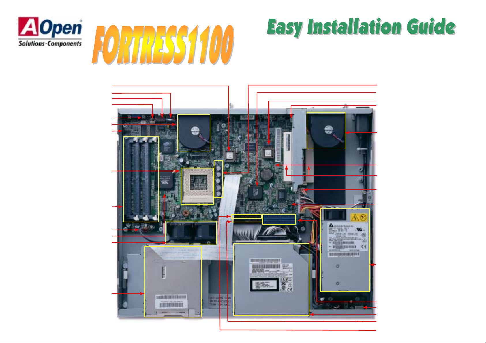
System FLASH BIOS
RJ45 Jac
RJ45 Jack
FAN4 Connecto
VGA Connecto
System FAN
JP5 VGA IRQ Jumpe
Low ESR Capacitors
VIA VT82C686B (SB)
IPMI ROM
FAN1 Connector
System FAN
370-pin CPU Socket with Voltage &
Frequency Auto-detection
supports Intel
®
Pentium™ III
(Both Coppermine & Tualatin are supported)
168-pin DIMM Socket x 3 supports
PC133 SDRAM maximum up to 3 GB
FAN3 Connecto
VIA 694T (NB)
CPU FAN x 2
Slim-type Floppy Diskette drive
JP3 CMOS Clear Jump
32 Bit PCI Slot x 2
TX 20-pin Power Connector
Power supply Fan Sensor
100W PFC Switching Power supply
RAID Channel x2
USB Connecto
Slim-type CD-ROM drive
CD-ROM Connector
TA 100 IDE Connector
Page 2
y
Everything you need to boot this
(
motherboard is included in this
Easy Installation Guide. For more
information, a complete Online
User's Manual can be found in the
Bonus Pack CD Disc. Thanks for
the help of saving our earth.
1. JP3 Clear CMOS
You can clear CMOS to restore system default setting. To
clear the CMOS, follow the procedure below.
1. Turn off the system and unplug the AC power.
2. Remove ATX power cable.
3. Locate JP3 and short pins 2-3 for a few seconds.
4. Return JP3 to its normal setting by shorting pin 1 & pin 2.
5. Connect ATX power cable back.
User Manual x 1
IDE ATA Cable x 2
Heat-sink x 1
Screw Package (10 HDD Screws)
Bonus Pack CD x 1
This Easy Installation Guide x 1
One set rubber feet (4)
PART NO: 90.53F30.001 DOC. NO: SX34-EG-E0112A
Normal
default)
Clear CMOS
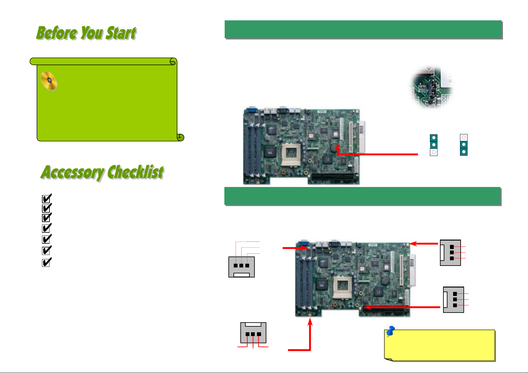
2. Installing CPU & System Fan
There are four system FAN connectors provided by Fortress1100 system. Each of them is a 3-pin
connector, which brings the failure report, 12V power and ground. The system FAN is designed with
redundanc
FAN4 Connector
FAN3 Connector
SENSOR
to prevent thermal disaster caused by FAN failure.
GND
+12V
SENSOR
GND
+12V
FAN1 Connector
Fan2 Connector
Note: Some CPU fans do not have
sensor pin so they cannot support fan
monitoring.
GND
+12V
SENSOR
GND
+12V
SENSOR
Page 3
r
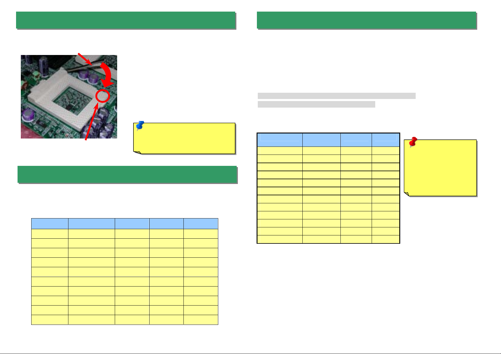
3. Installing Processor
CPU socket lever
CPU Pin 1 and cut edge
1. Pull up the CPU socket lever and up to
90-degree angle.
2. Locate Pin 1 in the socket and look for a
(golden) cut edge on the CPU uppe
interface. Match Pin 1 and cut edge.
Then insert the CPU into the socket.
3. Press down the CPU socket lever and
finish CPU installation.
Note: If you do not match the CPU
socket Pin 1 and CPU cut edge
well, it may damage the CPU.
4. Supported CPU Type
Fortress1100 supports one Coppermine (up to 1 GHz with 256 L2 cache) or Tualatin
(up to 1.26 GHz with 512K L2 cache) processor with external FSB up to 133 MHz.
Item Frequency 128KB 256KB 512KB
Coppermine 800MHz YES YES NO
Coppermine 866MHz YES YES NO
Coppermine 933MHz YES YES NO
Coppermine 1GHz YES YES NO
Coppermine 1.13GHz YES YES NO
Coppermine 1.26GHz YES YES NO
Tualatin 1GHz NO YES YES
Tualatin 1.13GHz NO YES YES
Tualatin 1.20GHz NO YES YES
Tualatin 1.26GHz NO YES YES
5. Setting CPU Voltage & Frequency
Setting CPU Core Voltage
This motherboard supports CPU VID function. The CPU core voltage will be automatically
detected and the range is from 1.05V to 1.825V. It is not necessary to set CPU Core Voltage
Setting CPU Frequency
This motherboard is CPU jumper-less design, the system can detect the CPU frequency
automatically, and no jumpers or switches are needed.
BIOS Setup > Frequency / Voltage Control > CPU Speed Setup
Core Frequency = CPU FSB Clock * CPU Ratio
CPU CPU Core
Frequency
Pentium III 800E 800MHz 100MHz 8x
Pentium III 850E 850MHz 100MHz 8.5x
Pentium III 533EB 533MHz 133MHz 4x
Pentium III 600EB 600MHz 133MHz 4.5x
Pentium III 667EB 667MHz 133MHz 5x
Pentium III 733EB 733MHz 133MHz 5.5
Pentium III 800EB 800MHz 133MHz 6x
Pentium III 866EB 866MHz 133MHz 6.5
Pentium III 933EB 933MHz 133MHz 7x
Pentium III 1G 1GHz 133MHz 7.5x
Pentium III 1.13G 1.13GHz 133MHz 8.5x
Pentium III 1.26G 1.26GHz 133MHz 9x
FSB Clock Ratio
Warning: We strongly
recommend you do
not overclocking your
CPU and system for
get more system
reliability.
Page 4

(
(
)
This jumper allows you to decide the system to support IDE RAID or ATA interface. The
default setting is IDE RAID.
The system is equipped with an intrusion alarm device. Whenever the opening of
the chassis triggers the sensor, the system will send out beep sound to inform
you. The connector is equipped with a foolproof device.
6. JP2 IDE RAID / ATA Controller Jumper
IDE RAID
default)
ATA
7. JP4 Intrusion Alarm Cable
Intrusion Alarm Cable Connector
8.JP5 VGA IRQ Jumper
This jumper allows you to enable or disable VGA sending IRQ to the system. The default
setting is Disable.
Disable
default
Enable
9. JP10 Power On By South Bridge or IPMI
This jumper allows you to decide to power on by south bridge or IPMI. The default
setting is By IPMI.
BY South Bridge
Enable
By IPMI
(Default)
Page 5

(
A
10. JP11 BIOS Restore Function
12. Connecting ATX Power Connector
This jumper allows you to enable or disable the BIOS restore function. The default settin g
is Disable.
Disable
default)
Enable
11. Connecting IDE and Floppy Cables
The system comes with a slim-type CD-ROM drive and a slim-type floppy disk drive.
Connect 40-pin, 80-wire IDE cable to IDE connector. A slim-type floppy disk drive is
connected with a special design cable. Be careful of the pin1 orientation. Wrong
orientation may cause system damage.
Floppy drive connector
The ATX power supply uses 20-pin connector shown below. The connector is equipped
with a foolproof device. Make sure you plug in the right direction.
+3.3V
-12V
COM
PS-ON
COM
COM
COM
-5V
+5V
+5V
13. Installing DIMM Sockets
This motherboard supports Advanced ECC memory Controller, 168-pin PC100 / PC133
SDRAM, Virtual Channel Memory (VCM), and ESDRAM up to 3GB.
+3.3V
+3.3V
COM
+5V
COM
+5V
COM
PWR OK
5VSB
+12V
TA 100 IDE connector
RAID primary channel
RAID secondary channel
CD-ROM drive connector
Page 6

A
y
14. Support 10/100 Mbps LAN Onboard
On the strength of Intel 82550 PHY on board, which is a highly-integrated Platform LAN
Connect device, it provides 10/100M bps Ethernet for office and home use, the Ethernet RJ45
connector is located on the back panel. The green LED indicates the link mode, it lights when
linking to network and blinking when transferring data. The orange LED indicates the transfer
mode, and it lights when data is transferring in 100Mbps mode. To enable or disable this
function, you may simply adjust it through BIOS.
Green/ACT
Orange/Speed
16. Back Panel
The picture shown below indicates the functions of all connectors on the real panel. The
connectors are all different in their shape or color. They all have foolproof devices. Please
make sure you plug in the right direction.
RJ45 LAN Jack
VGA Connector
TX Power
Connector
PS/2 Ke
System event
LED
board
PS/2 Mouse
COM1
15. PCI Bus Slots
The Fortress1100 has two 32-bit / 33 MHz PCI bus slots with a riser card. The riser card
provides an easy way to plug the PCI card in the system.
Riser Card
The picture shown below indicates the functions of LEDs of the front panel. The system
provides two USB ports on the front panel. Please make sure you plug in the right
direction.
System health
LED
Hard Disk LED
Power LED
17.Front Panel
USB Ports
Reset Button
Power Button
Page 7

r
r
y
18. Power-On and Load BIOS Setup
A
g
fter you finish the setting of jumpers and connect correct cables. Power on and enter the
BIOS Setup, press <Del> during POST (Power On Self Test). Choose "Load Default
Settin
" for recommended optimal performance.
Del
If you encounter any trouble to boot you system, follo w the procedures
accordingly to resolve the problem.
Start
Turn off the power and unplug the AC power cable, then remove al l
of the addon cards and cables, including VGA, IDE, FDD, COM1,
COM2 and Printer.
Make sure if the jumper settings for CPU and DRAMs are correct.
Clear CMOS.
19.Part Number and Serial Number
The Part Number and Serial number are printed on bar code label. You can find this
bar code label on the outside packing, on ISA/CPU slot or on component side of PCB.
For example:
Part No.
Part No. Serial No.
P/N: 91.88110.201 is part number, S/N: 91949378KN73 is serial number.
Serial No.
Install the VGA card. Then connect your monitor and keyboard.
Turn on the power, and check if
the power supply and CPU fan
work properly.
Check if there is display.
Press Ctrl, and Alt key at the
same time, hold them and then
press Del to see if the
s
During system rebooting, press Del to enter BIOS Setup. Choose
“Load Setup Default".
Turn off the system and
re-connect the IDE cable.
Check if the system can
reboot successfully.
Re-install Windows 95, Windows 98 or Windows NT.
Yes
Yes
stem reboots.
Yes
Yes
End
No
The problem was probably caused
by power supply or motherboard
failure. Please contact your reselle
or local distributor for repairing.
No
Perhaps your VGA card or monito
is defective.
No
It is very possible that your keyboard
is defective.
No
The problem should be caused by the
IDE cables or HDD itself.
Page 8

p
A
A
A
A
有限公司
A
A
A
Dear Customer,
Thanks for choosing AOpen products. To provide the best and fastest service to
our customer is our first priority. However, we receive numerous emails and
hone-calls worldwide everyday, it is very hard for us to serve everyone on time.
We recommend you follow the procedures below and see k help before contact
us. With your help, we can then continue to provide the best quality service to
more customers.
Thanks very much for your understanding!
Open T echnical Supporting Team
1
1
Online Manual: Please check the manual carefully and make sure the
jumper settings and installation procedure are correct.
http://www.aopen.com/tech/download/manual/default.htm
Test Report: We recommend to choose board/card/device from the
compatibility test reports for assembling your PC.
http://www.aopen.com/tech/report/default.htm
FAQ: The latest FAQ (Frequently Asked Questions) may contain a
solution to your problem.
http://www.aopen.com/tech/faq/default.htm
3
3
2
2
Pacific Rim
Open Inc.
Tel: 886-2-3789-5888
Fax: 886-2-3789-5899
China
艾尔鹏国际上海(股)
Tel: 86-21-6225-8622
Fax: 86-21-6225-7926
merica
Open America Inc.
Tel: 1-408-922-2100
Fax: 1-408-922-2935
Web Site: www.aopen.com
E-mail: Send us email by going through the contact form below.
English http://www.aopen.com/tech/contact/techusa.htm
Japanese http://www.aopen.co.jp/tech/contact/techjp.htm
Chinese http://www.aopen.com.tw/tech/contact/techtw.htm
German http://www.aopencom.de/tech/contact/techde.htm
French http://france.aopen.com/tech/contact/techfr.htm
Simplified Chinese http://www.aopen.com.cn/tech/contact/techcn.htm
Europe
Open Computer b.v.
Tel: 31-73-645-9516
Fax: 31-73-645-9604
Germany
Open Computer GmbH.
Tel: 49-2102-157700
Fax: 49-2102-157799
Japan
Open Japan Inc.
Tel: 81-048-290-1800
Fax: 81-048-290-1820
5
5
Download Software: Check out this table to get the latest updated
4
4
News Group: Our support engineer or professional users on the news
group probably had answered your problem.
http://www.aopen.com/tech/newsgrp/default.htm
7
7
BIOS/utility and drivers.
http://www.aopen.com/tech/download/default.htm
Contact Distributors/Resellers: We sell our products through resellers
6
6
and integrators. They should know your system configuration ver y well and
should be able to solve your problem more efficiently and provide important
reference for you if next time you want to buy something else from them.
Contact Us: Please prepare detail system configuration and error symptom
before contacting us. The part number, serial number and BIOS version
are also very helpful.
 Loading...