

Page 1

SSVV552200
SV520
DOC. NO. :SV520-OL-E0206A
OOnnlliinnee MMaannuuaal
l
A
Open
1
Page 2

SSVV552200
Copyright© 2002 AOpen Incorporated
All Rights Reserved.
AOpen SV520
User’s Guide
Changes may be made periodically to the information in this publication without obligation to notify
any person of such revision or changes. Such changes will be incorporated in new editions of this
manual or supplementary documents and publications. This company makes no representations or
warranties either expressed or implied, with respect to the contents hereof and specifically
disclaims the implied warranties of merchantability or fitness for a particular purpose.
No part of this publication may be reproduced., stored in a retrieval system, or transmitted, in any
form or by any means, electronic, mechanical, photocopy, recording, or otherwise, without the prior
written permission of AOpen Incorporated.
All brand and product names mentioned in this manual are trademarks and/or registered
trademarks of their respective companies.
OOnnlliinnee MMaannuuaal
l
A
2
Open
Page 3

SSVV552200 OOnnlliinnee MMaannuuaal
IImmppoorrttaanntt SSaaffeettyy IInnssttrruuccttiioonnss
1. Read these instructions carefully. Save these instructions for future reference.
2. Follow all warnings and instructions marked on the product.
3. Do not use this product near water.
4. Do not place this product on an unstable cart, stand, or table. The product may fall, causing
serious damage to the product.
5. Slots and openings in the cabinet and the back or bottom are provided for ventilation; to
ensure reliable operation of the product and to protect it from overheating, these openings
must not be blocked or covered. The openings should never block by placing the product on a
bed, sofa, rug, or other similar surface. This product should never be placed near or over a
radiator or heat register, or in a built-in installation unless proper ventilation is provided.
6. This product should be operated from the type of power indicated on the marking label. If
you are not sure of the type of power available, consult your dealer or local power company.
7. This product is equipped with a 3-wire grounding-type plug, a plug having a third (grounding)
pin. This plug will only fit into a grounding-type power outlet. This is a safety feature. If you are
unable to insert the plug into the outlet, contact your electrician to replace your obsolete outlet.
Do not defeat the purpose of the grounding-type plug.
8. Do not allow anything to rest on the power cord. Do not locate this product where persons will
l
A
3
Open
Page 4

SSVV552200
walk on the cord.
9. If an extension cord is used with this product, make sure that the total ampere rating of the
equipment plugged into the extension cord does not exceed the extension cord ampere rating.
Also, make sure that the total rating of all products plugged into the wall outlet does not
exceed 15 amperes.
10. Never push objects of any kind into this product through cabinet slots as they may touch
dangerous voltage points or short out parts that could result in a fire or electric shock. Never
spill liquid of any kind on the product.
11. Do not attempt to service this product yourself, as opening or removing covers may expose
you to dangerous voltage points or other risks. Refer all servicing to qualified service
personnel.
12. Unplug this product from the wall outlet and refer servicing to qualified service personnel
under the following conditions:
a. When the power cord or plug is damaged or frayed
b. If liquid has been spilled into the product
c. If the product has been exposed to rain or water
d. If the product does not operate normally when the operating instructions are followed.
Adjust only those controls that are covered by the operating instructions since
improper adjustment of other controls may result in damage and will often require
OOnnlliinnee MMaannuuaal
l
A
4
Open
Page 5

SSVV552200 OOnnlliinnee MMaannuuaal
extensive work by a qualified technician to restore the product to normal condition.
e. If the product has been dropped or the cabinet has been damaged
f. If the product exhibits a distinct change in performance, indicating a need for service
Use only the proper type of power supply cord set for this unit. It should be a detachable
type: UL listed/CSA certified, type SVT/SJT, rated 6A 125V minimum, VDE approved or its
equivalent. Maximum length is 15 feet (4.6 meters).
l
A
5
Open
Page 6
SSVV552200
CCDD--RROOMM SSaaffeettyy WWaarrnniinngg
DANGER
INVISIBLE RADIATION WHEN OPEN.
AVOID EXPOSURE TO BEAM.
CLASS 1 LASER PRODUCT
APPAREIL A LASER DE CLASSE 1
LASER KLASSE 1
LOUKAN 1 LASERLAITE
PRODUIT LASER
CATEGORIE 1
OOnnlliinnee MMaannuuaal
l
A
6
Open
Page 7

SSVV552200 OOnnlliinnee MMaannuuaal
FFCCCC CCllaassss AA RRaaddiioo FFrreeqquueennccyy IInntteerrffeerreennccee
SSttaatteemmeenntt
Note:
This equipment has been tested and found to comply with the limits for a Class B digital device,
pursuant to Part 15 of FCC Rules. These limits are designed to provide reasonable protection
against harmful interference in a residential installation. This equipment generates, uses, and can
radiate radio frequency energy and, if not installed and used in accordance with the instructions,
may cause harmful interference to radio communications. However, there is no guarantee that
interference will not occur in a particular installation. If this equipment does cause harmful
interference to radio or television reception, which can be determined by turning the equipment off
and on, the user is encouraged to try to correct the interference by one or more of the following
measures:
1. Reorient or relocate the receiving antenna.
2. Increase the separation between the equipment and receiver.
3. Connect the equipment into an outlet on a circuit different from that to which the receiver
is connected.
4. Consult the dealer or an experienced radio/television technician for help.
Notice 1:
l
A
7
Open
Page 8

SSVV552200
The changes or modifications not expressly approved by the party responsible for compliance
could void the user's authority to operate the equipment.
Notice 2:
Shielded interface cables, if any, must be used in order to comply with the emission limits.
AAbboouutt tthhiiss MMaannuuaall
Purpose
This user’s guide aims to give you the information you need to operate the system properly and
tells you how to install internal components.
OOnnlliinnee MMaannuuaal
l
A
8
Open
Page 9
SSVV552200 OOnnlliinnee MMaannuuaal
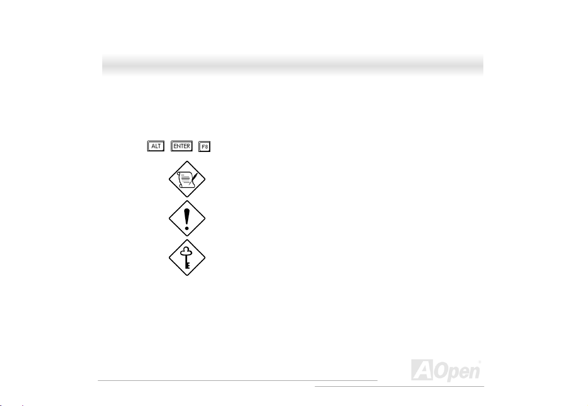
CCoonnvveennttiioonnss
The following conventions are used in this manual:
Text entered by user Represents text input by the user.
, , , etc….
Represent the actual keys that you have to
press on the keyboard.
NOTE
Gives bits and pieces of additional
information related to the current topic.
CAUTION
Gives precautionary measures to avoid
possible hardware or software problems.
IMPORTANT
Reminds you to take specific actions
relevant to the accomplishment of
procedures.
l
A
9
Open
Page 10

SSVV552200
OOnnlliinnee MMaannuuaall
WWhhaatt’’ss iinn tthhiiss mmaannuuaall
SV520 ...................................................................................................................................................................1
IMPORTANT SAFETY INSTRUCTIONS .................................................................................................................3
CD-ROM SAFETY WARNING............................................................................................................................6
FCC CLASS A RADIO FREQUENCY INTERFERENCE STATE ME NT ......................................................................7
ABOUT THIS MANUAL....................................................................................................................................... 8
CONVENTIONS...................................................................................................................................................9
WHAT’S IN THIS MANUAL ...............................................................................................................................10
1.1 INTRODUCTION .........................................................................................................................................12
1.2 FEATURES..................................................................................................................................................13
1.2.1 Front Panel........................................................................................................................................ 13
1.2.2 Real Panel .........................................................................................................................................17
1.2.3 Internal Component...........................................................................................................................20
1.2.4 HSC6 Jumpers and Connectors (Optional) ......................................................................................22
1.3 OPENING THE HOUSING PANELS...............................................................................................................25
1.3.1 Opening the front panel door............................................................................................................25
A
Open
10
Page 11

SSVV552200 OOnnlliinnee MMaannuuaal
1.3.2 Removing the front panel door..........................................................................................................26
1.3.3 Removing the side panels ..................................................................................................................27
1.4 INSTALLING AND REMOVING DEVICE DRIVES .........................................................................................28
1.4.1 Removing drive bay covers ...............................................................................................................28
1.4.2 Installing and Removing a 3.5” Device Drive ..................................................................................29
1.4.3 Installing and Removing a 5.25” Device Drive ................................................................................33
1.5 INSTALLING A HOT-SWAP CAGE (OPTIONAL) ...........................................................................................36
1.5.1 Installing a HSC6 Hot-Swap Cage ...................................................................................................37
1.5.2 Hot-Swapping SCSI SCA Hard Disk Drive.......................................................................................39
1.5.3 Hot-Swapping the Hot-Plug Fan-Sink Module.................................................................................42
1.6 HOT-SWAPPING REDUNDANT POWER SUPPLY..........................................................................................44
1.7 REPLACING THE POWER SUPPLY FAN .......................................................................................................48
1.8 HOT SWA P REDUNDANT CHASSIS FAN .....................................................................................................50
1.8.1 Hot-Swap Fan Base Board................................................................................................................51
1.8.2 Replacing Housing Fans ...................................................................................................................52
1.9 INSTALLING AN EXPANSION CARD ...........................................................................................................54
l
11
A
Open
Page 12

SSVV552200
OOnnlliinnee MMaannuuaall
11..11 IInnttrroodduuccttiioonn
This installation guide describes the features of the SV520 housing and tells you how to install the
basic system components such as disk drives, a motherboard, or expansion boards.
A
Open
12
Page 13
SSVV552200 OOnnlliinnee MMaannuuaal
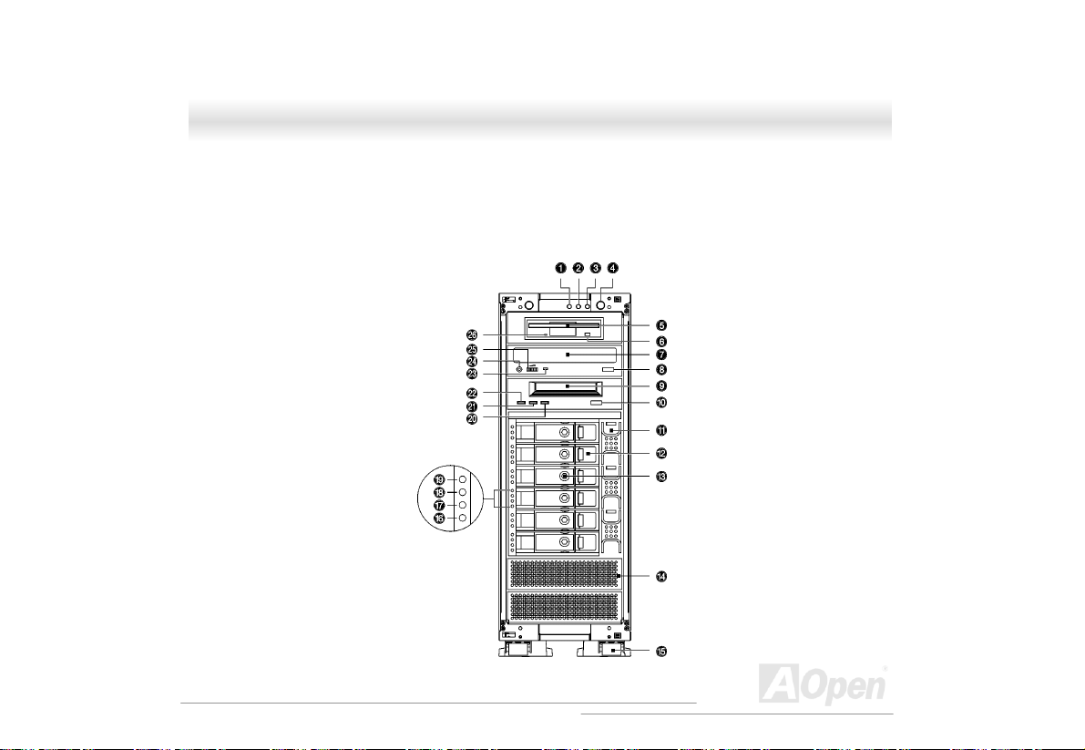
11..22 FFeeaattuurreess
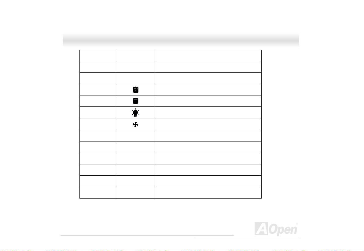
1.2.1 Front Panel
Additional duplicate keys can be found at the back of the system.
l
13
A
Open
Page 14
SSVV552200
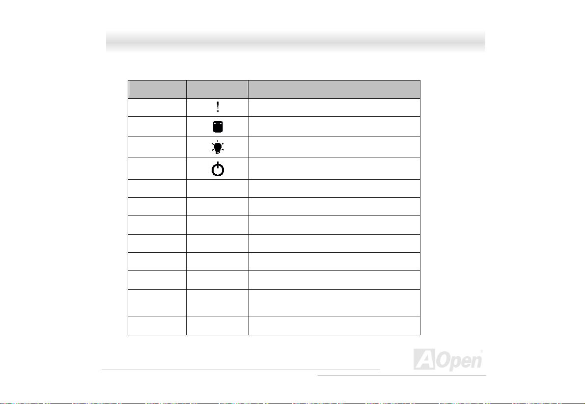
No. Icon Item
OOnnlliinnee MMaannuuaall
1
2
3
4
5 3.5” FDD
6 3.5” FDD eject button
7 CD-ROM tray (Optional)
8 CD-ROM tray eject button
9 Tape drive (Optional)
10 Tape drive eject button
11 Hot-swap redundant HSC6 cage fan (Optional,
12 HSC6 HDD trays (Optional, six trays)
Event log LED
HDD access LED
Power/Suspend LED
Power button
three fans)
14
A
Open
Page 15
SSVV552200 OOnnlliinnee MMaannuuaal
13 HSC6 HDD tray lock (Optional)
14 Drive bay cover
15 Housing wheels
16
17
18
19
20 Drive LED (Amber) (Optional)
21 Media LED (Green) (Optional)
22 Clean LED (Green) (Optional)
23 CD-ROM drive activity LED(Optional)
24 Headphone/earphone port(Optional)
25 Volume control(Optional)
SCSI drive error LED(Optional)
SCSI drive activity LED(Optional)
SCSI drive power LED(Optional)
Hot-swap redundant fan fail LED(Optional)
l
15
A
Open
Page 16
SSVV552200
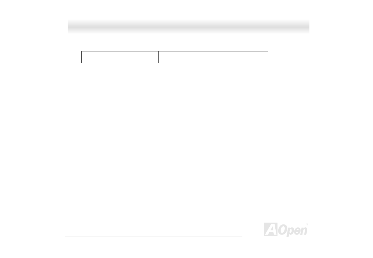
26 3.5” FDD activity LED
OOnnlliinnee MMaannuuaall
16
A
Open
Page 17
SSVV552200 OOnnlliinnee MMaannuuaal
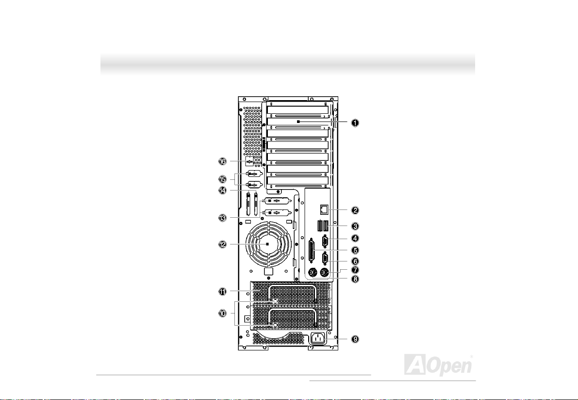
1.2.2 Real Panel
l
17
A
Open
Page 18

SSVV552200
No. Item
1 Add-on card brackets
2 RJ45 LAN port
3 1st USB port
4 VGA D-sub 15-pins connector
5 Parallel port
6 Serial port (COM1)
7 PS/2 keyboard connector
8 PS/2 mouse connector
9 System power socket
10 Hot-swap power supply activity LED (Orange
when fail)
11 Hot-swap power supply (Redundant power
supply is optional)
12 Fan
OOnnlliinnee MMaannuuaall
18
A
Open
Page 19

SSVV552200 OOnnlliinnee MMaannuuaal
13 Parallel port punch out hole
14 SCSI connector punch out hole
15 Serial port punch out hole
16 NMI switch punch out hole
l
19
A
Open
Page 20

SSVV552200
1.2.3 Internal Component
OOnnlliinnee MMaannuuaall
20
A
Open
Page 21

SSVV552200 OOnnlliinnee MMaannuuaal
No. Item
1 Drive bays
2 M/B (Optional)
3 Expansion brackets
4 Rear fan
5 Power supply
6 Front fans (Two fans)
l
21
A
Open
Page 22

SSVV552200
1.2.4 HSC6 Jumpers and Connectors (Optional)
OOnnlliinnee MMaannuuaall
22
A
Open
Page 23

SSVV552200 OOnnlliinnee MMaannuuaal
Connector or Jumper Description
CN1 I2C buffer connector
CN2 Front power LED connector
CN3 SCSI 68-pin P connector - Out
CN4 SCSI 68-pin P connector - Out
CN5 For SAF-TE card use
CN6 For SAF-TE card use
CN7 SCSI 68-pin P connector - In
CN8 SCSI 68-pin P connector - In
Fan 1 to 3 Hot-plug fan-sink connector
JP1/JP4 Terminator power source
1. Short: Both from backplane and host
2. Open: Only from host
JP2 Power connector*
1
l
23
A
Open
Page 24

SSVV552200
1. For the SCSI backplane board’s loading requirement, please insert the independent power
2. When you use the LVD SCSI hot-swap cage to arrange your system hard drives, please
JP3 Power connector
Slot 1 to 6 SCSI hard disk slots
SW1 Slot 1 ID switch
SW2 Slot 2 ID switch
SW3 Slot 3 ID switch
SW4 Slot 4 ID switch
SW5 Slot 5 ID switch
SW6 Slot 6 ID switch
cable that don’t connect to other device to each power connector on backplane board.
remove all the jumpers on each SCSI hard drive and use the switches on the backplane board
(SW1~SW6) to set the hard drive’s ID.
*2
OOnnlliinnee MMaannuuaall
24
A
Open
Page 25

SSVV552200 OOnnlliinnee MMaannuuaal
11..33 OOppeenniinngg tthhee HHoouussiinngg PPaanneellss
1.3.1 Opening the front panel door
To open front door:
1. Insert the key, push, and then turn it clockwise. If you are using the chassis for the first time,
you can find the key attach to the rear of the chassis.
2. Press the latch and open the door
l
25
A
Open
Page 26

SSVV552200
OOnnlliinnee MMaannuuaall
1.3.2 Removing the front panel door
The door is attached to the main housing by screw-less hinges. Follow these steps to remove the
door:
1. Unlock the door.
2. Open it up to a 45° angle.
3. Lift it up and pull out to detach.
26
A
Open
Page 27

SSVV552200 OOnnlliinnee MMaannuuaal
1.3.3 Removing the side panels
To remove the side panels:
1. Turn off the power to the system unit and unplug all cables.
2. Unscrew two thumbscrews located at the back of the side panels.
3. Gently pull back the side panel and detach
l
27
A
Open
Page 28

SSVV552200
OOnnlliinnee MMaannuuaall
11..44 IInnssttaalllliinngg aanndd RReemmoovviinngg DDeevviiccee DDrriivveess
The chassis has nine 5.25” drive bay. You can install additional storage devices like CD-ROM
drives, digital audio tape (DAT) drives or hard disk drives on the empty bays.
Turn off the power switch and unplug the power cord
before installing or removing diskette drives.
1.4.1 Removing drive bay covers
The drive bay cover protects the inside of the chassis when the drive bay is not occupied.
To remove a drive bay cover:
1. Open the front panel door and remove the side panels. See “Opening the housing panel
page 25 for more information.
2. Detach the drive bay cover. Use a Phillips screwdriver to remove one screws located on the
right side of the drive bay cover.
3. Press the latch located on the left side of the drive bay using your finger. Pull out the drive bay
cover. Keep the drive bay cover for future use.
28
” on
A
Open
Page 29

SSVV552200 OOnnlliinnee MMaannuuaal
1.4.2 Installing and Removing a 3.5” Device Drive
The housing comes with a 5.25” plastic casing for installing 3.5” storage devices.
To install 3.5-inch device drives:
1. Open the front panel of the housing. See “Opening the housing panel
page 25 for more information.
2. Attaching the 3.5” storage devices to the 5.25” plastic casing with four
screws.
3. Attaching the drive rail to one side of the plastic casing and secure it with
two screws. Do the same thing to the other side.
” on
l
29
A
Open
Page 30

SSVV552200
4. Insert the casing into the bay. If the drive bay has a cover, remove the
cover first. See “Removing drive bay covers
5. Secure the casing with two screws.
OOnnlliinnee MMaannuuaall
” on page 28.
30
A
Open
Page 31

SSVV552200 OOnnlliinnee MMaannuuaal
6. Connect the power cable and signal cables to the storage devices.
7. Reinstall the side panel.
l
31
A
Open
Page 32

SSVV552200
To remove a 3.5” storage device:
1. Open the front panel door and remove the side panels. See “Opening the housing panels
2. Disconnect the power and signal cables.
3. Use a Phillips screwdriver to remove the screws located on the right side of the plastic casing.
4. Again, use a Phillips screwdriver to remove the screws located underneath the storage device.
5. Use the drive bay cover to cover the drive bay. Insert it into the empty drive bay and secure it
6. Reinstall the side panel.
page 25 for more information.
Gently pull out the plastic casing.
Detach the 3.5” storage device from the plastic casing.
with one screw.
OOnnlliinnee MMaannuuaall
” on
32
A
Open
Page 33

SSVV552200 OOnnlliinnee MMaannuuaal
1.4.3 Installing and Removing a 5.25” Device Drive
You may install a CD-ROM, digital-audio tape (DAT), hard disk, diskette drive or any other
5.25-inch device into the drive bay.
To install 5.25-inch devices:
1. Open the front panel door and remove the side panels. See “Opening the housing panels
page 25 for more information.
2. Attach the driver rail to one side of the plastic casing and secure it with two screws. Do the
same thing to the other side.
3. Insert the 5.25” storage drive into the bay. If the drive bay has a cover, remove the cover first.
See “Removing drive bay covers
” on page 28.
” on
l
33
A
Open
Page 34

SSVV552200
4. Secure the storage drive with two screws.
5. Connect the power cable and signal cables to the external devices.
6. Reinstall the side panels.
OOnnlliinnee MMaannuuaall
34
A
Open
Page 35

SSVV552200 OOnnlliinnee MMaannuuaal
To remove a 5.25” storage device:
1. Open the front panel door and remove the side panels. See “Opening the housing panels
page 25 for more information.
2. Disconnect the power and signal cables.
3. Use a Phillips screwdriver to remove the screws located on the right side of the storage
device.
4. Gently pull out the storage drive to remove.
5. Use the drive bay cover to cover the drive bay. Insert it into the empty drive bay and secure it
with one screw.
6. Reinstall the side panel.
” on
l
35
A
Open
Page 36

SSVV552200
OOnnlliinnee MMaannuuaall
11..55 IInnssttaalllliinngg aa HHoott--SSwwaapp CCaaggee ((OOppttiioonnaall))
The hot-swap cage occupied four drive bays. For more information about the backplane board,
please refer to “
The HSC6 hot-swap cage includes the following components:
HSC6 Jumpers and Connectors
” on page 22,.
• One hot-swap cage (with back plane board attached)
• Six hard disk drive trays
• Three hot-plug fan-sink modules
• One SCSI terminator
• Two SCSI cables
• One I
2
C cable.
36
A
Open
Page 37

SSVV552200 OOnnlliinnee MMaannuuaal
1.5.1 Installing a HSC6 Hot-Swap Cage
To install the hot-swap cage into the housing:
1. Open the front panel door and remove the side panels. See “Opening the housing panels
page 25 for more information.
2. Attach two pairs of drive rails on each side of the hot-swap cage. Secure the rails with eight
screws.
3. Insert the hot-swap cage into the drive bays and secure the hot-swap cage with four screws.
” on
l
37
A
Open
Page 38

SSVV552200
4. Attach the following to the HSC6 backplane board and attach the other end of the connector
cable to the motherboard.
a. Power cables
b. SCSI terminator
2
C cable (CN1, connect to motherboard)
c. I
d. SCSI cable (Connect to motherboard)
e. SCSI channel A to channel B connection cable
We suggest you use the lower four 5.25” bays for better heat
dissipation.
38
OOnnlliinnee MMaannuuaall
A
Open
Page 39

SSVV552200 OOnnlliinnee MMaannuuaal
1.5.2 Hot-Swapping SCSI SCA Hard Disk Drive
The hot-swap cage supports up to six hot-swapping SCSI SCA hard disk drives. You can hot-swap
(remove an replace) a hard disk drive any time when it fails to operate (indicated by the yellow
LED).
Do not remove a hard disk drive when active. This may
cause undue damage to the hard disk drive.
l
39
A
Open
Page 40

SSVV552200
Follow these steps to install a hot swappable SCSI drive:
1. Use the hex key provided with the system to unlock the drive tray.
2. Use your finger to release the drive tray and then pull it out.
OOnnlliinnee MMaannuuaall
40
A
Open
Page 41

SSVV552200 OOnnlliinnee MMaannuuaal
3. Place a hard disk on the tray. Secure it with four screws with the metal holder as shown below.
4. Insert the tray into the hot-swap cage with the lever still extended. Make sure that the drive is
properly inserted before closing the lever.
5. Push the lever back until it clicks into place.
l
41
A
Open
Page 42

SSVV552200
OOnnlliinnee MMaannuuaall
1.5.3 Hot-Swapping the Hot-Plug Fan-Sink Module
The hot-swap cage supports up to three hot-plug fan-sink modules to keep it cool. You can
hot-swap (remove and replace) a hot-plug fan-sink any time when it fails to operate (indicated by
the yellow LED).
Follow these steps to replace a hot-plug fan-sink module:
1. Insert your pointing finger and your thumb into the fan-sink module.
2. Squeeze the latch to release the fan and gently pull it out.
42
A
Open
Page 43

SSVV552200 OOnnlliinnee MMaannuuaal
3. Insert a new fan-sink into the hot-swap cage. Push the fan-sink until it locks into place.
l
43
A
Open
Page 44

SSVV552200
OOnnlliinnee MMaannuuaall
11..66 HHoott--SSwwaappppiinngg RReedduunnddaanntt PPoowweerr SSuuppppllyy
The power subsystem consists of two hot-swappable power supply module bays that allow the
installation of two 337-watts power supply modules in a hot-swappable redundant configuration. A
redundant power configuration enables a fully-configure system to continue running even if one
power supply fails.
The SV520 comes with one hot-swappable redundant power
supply installed.
To install a hot-swappable redundant power supply:
1. Insert the power supply into the power supply cage
Make sure that the power supply is properly inserted.
44
A
Open
Page 45

SSVV552200 OOnnlliinnee MMaannuuaal
2. Secure the power supply with a screw.
l
45
A
Open
Page 46

SSVV552200
To remove a hot-swappable redundant power supply:
1. Remove the screw using a Phillips screwdriver.
2. Press the latch to release the power supply and gently pull it out using the metal handle.
An orange colored LED indicates a failed power supply.
OOnnlliinnee MMaannuuaall
46
A
Open
Page 47

SSVV552200 OOnnlliinnee MMaannuuaal
The power supply subsystem should supply a minimum of
337 Watts to the whole system. If you only have one power
supply or if you have tow power supplies and are planning to
remove both of them, remember to turn off the power first
and disconnect the power cord from the electrical outlet.
l
47
A
Open
Page 48

SSVV552200
OOnnlliinnee MMaannuuaall
11..77 RReeppllaacciinngg tthhee PPoowweerr SSuuppppllyy FFaann
To replace the power supply fan:
1. Open the front panel door and remove the right panel. See “Opening the housing panels
page 25 for more information.
2. Insert your pointing finger and thumb into the power supply fan.
3. Squeeze the latch to release the fan and gently pull it out.
48
” on
A
Open
Page 49

SSVV552200 OOnnlliinnee MMaannuuaal
4. Insert a new fan and gently push it down until it locks into place.
l
49
A
Open
Page 50

SSVV552200
OOnnlliinnee MMaannuuaall
11..88 HHoott SSwwaapp RReedduunnddaanntt CChhaassssiiss FFaann
The chassis can house five cooling fans, however, it only needs a minimum of three cooling fans to
operate properly. These fans are distributed inside the chassis to cool down the system (two in
front and one at the back). The rear cooling fan is fixed and not hot-swappable. You have to
shutdown the system before changing the rear cooling fan. However, the cooling fans in front are
hot-swappable. When the front cooling fans becomes defective, you can simple take it out and put
a new one in even when the system is operating.
Make sure that there are three cooling fans (two in front and
one at rear) distributed in the chassis to ensure proper
system operation. Also, remember to shutdown the system
when changing a defective rear cooling fan.
50
A
Open
Page 51

SSVV552200 OOnnlliinnee MMaannuuaal
1.8.1 Hot-Swap Fan Base Board
l
51
A
Open
Page 52

SSVV552200
Connector or Jumper Description
JP1 Power connector
JP2 Signal cable (4-pin)
Fan1 to 4 Hot-plug fan connector
OOnnlliinnee MMaannuuaall
1.8.2 Replacing Housing Fans
To change a rear housing fan:
1. Shutdown the system
2. Open the front panel door and remove the side panels. See “Opening the housing panels
page 25 for more information.
3. Remove the fan cable from the motherboard.
4. Press the fan holder arm outward until it is loose enough for the cooling fan to come through.
5. Replace the defective cooling fan.
6. Reattach the fan cable to the motherboard.
7. Close the chassis panel and restart the system.
To change a front hot-swap housing fan:
” on
52
A
Open
Page 53

SSVV552200 OOnnlliinnee MMaannuuaal
1. Open the front panel door and remove the side panels. See “Opening the housing panels” on
page 25 for more information.
2. See which of the fan is defective. Refer to the LED located at the bottom side of each fan.
3. Insert your forefinger into the grasp hole and use your thumb to press the latch to release the
defective fan.
4. Pull out the fan and replace it with a good one. Make sure that the fan is operating properly.
5. Close the chassis panel.
l
53
A
Open
Page 54

SSVV552200
OOnnlliinnee MMaannuuaall
11..99 IInnssttaalllliinngg aann EExxppaannssiioonn CCaarrdd
The expansion card connects to the motherboard expansion slots. The number of expansion slots
available depends on the motherboard that you want to install. However, the chassis can only
accommodate a maximum of seven expansion cards.
To install an expansion card:
1. Open the front panel door and remove the side panels. See “Opening the housing panels
page 25 for more information.
2. Remove the expansion slot bracket opposite an empty expansion slot. Save the screw for
later use.
54
” on
A
Open
Page 55

SSVV552200 OOnnlliinnee MMaannuuaal
3. Align and insert the expansion card to the empty expansion slot.
4. Secure the expansion card to the chassis with a screw.
5. Reinstall the side panel.
l
55
A
Open
 Loading...