

Page 1
JukeBox / VividBios Design Guide
DDeessiiggnn YYoouurr OOwwnn JJuukkeeBBooxx PPllaayyeerr SSkkiinn
Have you ever dreamed about sharing your innovation with people all around the world? Now AOpen
offers you a chance and helps your dream come true. You are very welcomed to upload your innovative
design of JukeBox Player to our website and let users share your design. Only by following a set of simple rules plus a little imagination,
you can design any JukeBox Player you want easily. Below is what you should take care of when designing your own JukeBox Player.
Before you start
Before you start the design, there are several points you should notice.
The picture size should be limited in 640 pixels x 480 pixels.
The picture can be GIF, dynamic GIF or BMP format.
Due to limited BIOS memory, it would be wise if you can have the design as small as possible.
Design Procedures
Follow the steps one by one, you can design your own JukeBox Player easily.
1. Open a new image in any drawing software like Photoshop and set the image size to 640 x 480 pixels. This size area is where you
can draw any picture on. Please note that if your image format is dynamic GIF, the 1
design.
2. Pinpoint a display area which is the screen your player will show LED functions on it. Locate the up left corner at pixel (217, 170) and
lower right corner at pixel (340, 217) like Fig.1. It is not necessary that you have to make it rectangular, however you should leave
at least this sized area for LED presentation like Fig.2.
st
picture will become the background of your
Page 2
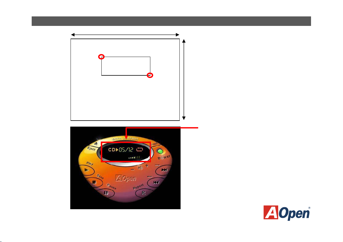
Fig.1
Fig.2
JukeBox / VividBios Design Guide
640pixels
Pixel(217, 170)
Display Screen Area
480pixels
Pixel(340,217)
Display Screen Area
Page 3
JukeBox / VividBios Design Guide
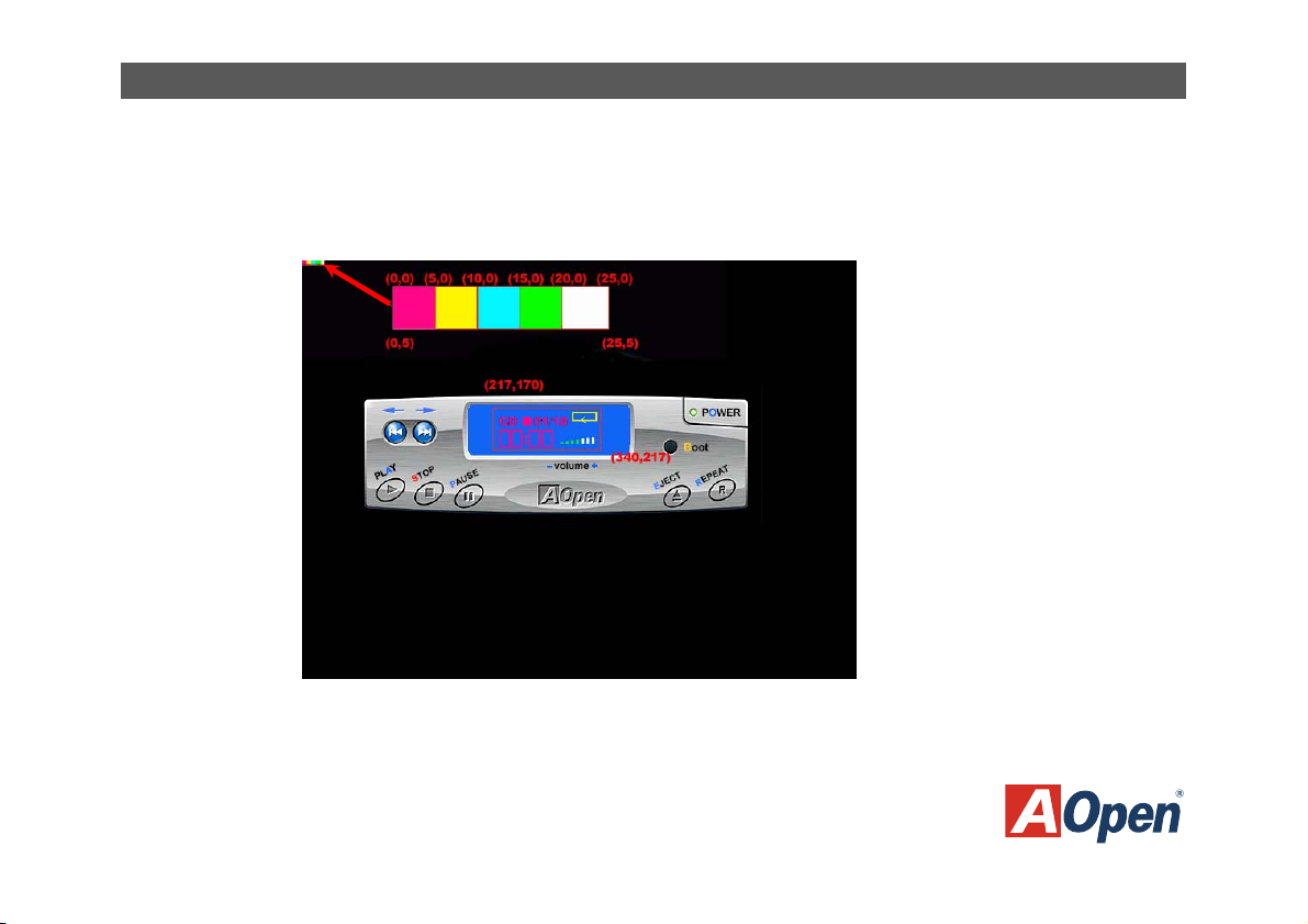
3. After marking above two areas, you can start to design the JukeBox Player you like.
4. Lastly, you can decide the image effect of the display screen by defining specific colours you desire. However, you have to let us
know your definition by placing a colour bar on the up right corner of the image. Please use a square sized 5x5 pixels to represent
the particular colour you use in display screen like Fig.3 below.
Fig.3
Page 4

JukeBox / VividBios Design Guide
Note: Please place the specific colour square in the correct order like Fig.4.
st
1
square: represents the colour of LED information.
nd
2
square: represents the colour of REPEAT icon.
rd
3
square: represents the colour of the music track.
th
4
square: represents the foreground colour of the VOLUME adjustment.
th
5
square: represents the background colour of the VOLUME adjustment.
Fig.4
1st 2nd 3rd 4th 5th
CD 01/18
Page 5

JukeBox / VividBios Design Guide
DDeessiiggnn YYoouurr OOwwnn VViivviidd BBIIOOSS SSccrreeeenn
Same with JukeBox Player, you can also design your own Vivid BIOS. By following a set of simple rules
plus a litter imagination, you can design your own unique BIOS screen. Below is what you should take
care of when designing your own Vivid BIOS.
Before you start
Before you start the design, there are several points you should notice.
The picture size should be limited in 640 pixels x 480 pixels.
The screen should be 256-colour BMP or GIF format. Please note that only global colour table can be supported in GIF
format screen and interlaced GIF is still not supported yet.
Design Procedures
Follow the steps one by one, you can design your own Vivid BIOS screen easily.
1. Open a new image in any drawing software like photoshop and set the image size to 640 x 480 pixels.
Page 6

2. Pinpoint a message area where your POST
information will show on it. Locate the up left
corner at pixel (0, 0) and lower right corner at
pixel (504, 365) like Fig.1. Please note that you
have to leave POST area empty so that the
POST information can be shown correctly.
3. Pinpoint a logo area where you can place any
logo you like or just place our AOpen logo at
pixel(639, 428) like Fig.2.
Fig.1
Fig.2
480pixels
JukeBox / VividBios Design Guide
640pixels
Pixel(0, 0)
Message Area
480pixels
Pixel(504,365)
640pixels
Logo Area
Pixel(639,428)
Page 7

4. Pinpoint a string area where string messages
will be shown here at pixel(0,428)-pixel(639,
479) like Fig.3. You have also to leave this area
empty to let the string information shown
correctly. Here we have a sample like Fig.4.
5. You can decide the image effect of your Vivid
BIOS by defining specific colours you desire.
Also, you have to let us know your definition by
placing a colour bar on the left bottom corner of
the string area like Fig.4 shown above. Please
use a square sized 10x10 pixels to represent
the particular colour you use. There will be an
Award logo shown xon POST area when
system is running POST, and you can also
define its colour.
Colour Definition
Fig.3
480pixels
Fig.4
JukeBox / VividBios Design Guide
640pixels
Pixel(0,428)
String Area
Pixel(639,479)
Page 8

JukeBox / VividBios Design Guide
Note: Please place the specific colour square in the correct order like Fig.5.
1st square: represents the background colour of string area.
2nd square: represents the colour of POST information.
3rd square: represents the colour of highlighted information.
4th square: represents the colour of the Award logo.
6. Lastly, if you desire to design your Vivid BIOS into animation style, you have to set the disposal method to “Don’t dispose” and the
delay time you think suitable.
1st 2nd 3rd 4th
Fig.5
 Loading...