

Page 1

Table of Contents
Table of Contents
Table of Contents................................................................................... 1
1.1 A Thank-you Note Before You Get Start..........................................................3
1.2 Features of This Manual ...............................................................................4
1.3 Safety Information ......................................................................................4
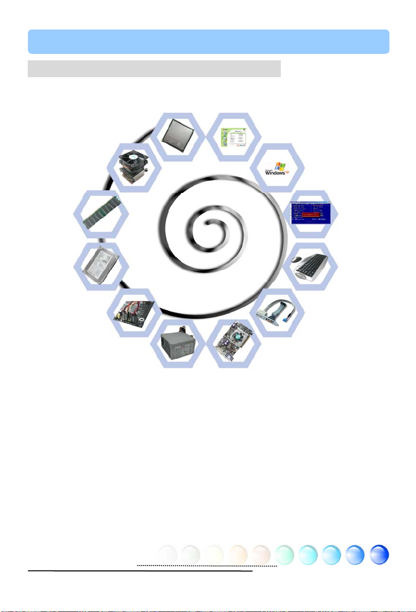
Chapter 2 Introduction to This Motherboard............................................... 5
2.1 How does your motherboard look like?...........................................................5
2.2 Specification...............................................................................................6
2.3 Block Diagram ............................................................................................7
Chapter 3 Hardware Installation............................................................... 8
3.1 Quick Installation Procedure .........................................................................8
3.2 Installation You Have to Know.......................................................................9
Installing CPU ............................................................................................ 9
Installing CPU and System Fans ..................................................................10
Installing Memory Modules .........................................................................11
Connecting IDE and Floppy Cables ..............................................................12
Connecting Front Panel Cable .....................................................................13
Connecting ATX Power Cables.....................................................................14
3.3 Other Installation for Your Reference ...........................................................15
Setting CPU Voltage and Frequency .............................................................15
Connecting Serial ATA................................................................................16
Adjusting your Hard Disk Setting.................................................................17
Connecting AGP 8X Expansion Slot ..............................................................18
Connecting IrDA........................................................................................19
10/100/1000Mbps LAN Supported (1000Mbps for s760GXm-SL only) ..............20
Connecting USB2.0....................................................................................21
Connecting S/PDIF ....................................................................................22
Super 5.1 Channel Audio Effect...................................................................23
1
Page 2

Connecting Front Audio..............................................................................24
Connecting CD_IN.....................................................................................25
Connecting AUX_IN ...................................................................................26
Connecting Case Open ...............................................................................27
Connecting COM2......................................................................................28
Colored Coded Back Panel ..........................................................................29
LED Indication ..........................................................................................30
3.4 Jumper Settings........................................................................................ 31
Chapter 4 Special Features and Utilities................................................... 32
RAID (Redundant Array of Independent Disks) ................................................... 32
RAID BIOS Setting Utility (for s760GXm-SL / s760GXm-S only)......................32
Other Useful Features...................................................................................... 33
Chapter 5 Setting BIOS......................................................................... 34
Introduction .............................................................................................34
How To Use Phoenix-Award™ BIOS Setup Program .......................................35
How To Enter BIOS Setup ..........................................................................35
BIOS Upgrade under Windows environment..................................................36
Vivid BIOS technology ...............................................................................38
Chapter 6 Installing Drivers................................................................... 39
6.1 Installing Drivers.......................................................................................40
6.2 Installing Utilities ...................................................................................... 41
Chapter 7 Troubleshooting..................................................................... 42
Chapter 8 Technical Support .................................................................. 43
Model Name and BIOS Version....................................................................44
Register Your Motherboard .........................................................................44
Technical Support......................................................................................45
2
Page 3

1.1 A Thank-you Note Before You Get Start
First of all, we would like to express our gratitude for purchasing AOpen products.
Once again, this motherboard is designed uniquely to meet all your personal
needs with our gre at industr y-d esigning a bility and our ev erlasti ng perse ver ance
to the quality of all our products.
This manual will introduce you how this motherboard is installed. Please keep it
well for your future reference. If you lost your printed manual, you may also go to
our website at http://www.aopen.com to download the updated file.
Now, we would like to invite you to personally experience this user-friendly
manual and all of the powerful functions this AOpen product offers.
The logos of Adobe and Acrobat are the registered trademarks of Adobe Systems
Incorporated.
The logos of AMD, Athlon, and Duron are the registered trademarks of Advanced Micro
Devices, Inc.
The logos of Intel, Intel Celeron, Pentium II, III and Pentium 4 are the registered
trademarks of Intel Corporation.
The logos of nVidia are the registered trademarks of nVidia Corporation.
The logos of Microsoft, Windows are the registered trademarks of Microsoft Corporation in
America and other countries.
All the titles of the products and the trademarks mentioned in this manual are for the
purpose of illustrative conveniences and are possessed by their respective firms.
We regret not informing about any changes in usage standards and other related
information. AOpen reserves the right of altering or modifying the content of this manual. In
case of any mistakes or incorrect descriptions, which include those on the products, AOpen
makes no guarantee or commitments.
This document is based on the copyright laws in order to protect our company and reserve
all rights.
Under no circumstances are any types of duplicating and loading this brochure in any
databases and media permitted except the permission signed on formal document by
AOpen Company.
1996-2004 Copyrights, AOpen Ltd. All rights reserved.
3
Page 4
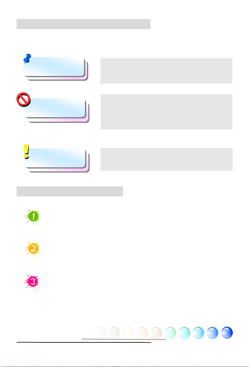
1.2 Features of This Manual
T o help you g rab the useful information of this mothe rboard and aware of certain
conditions that you might need to know, you will see the icons below frequently:
Note
Warning / Caution
Warning
Tip
Warning
This contains knowledge you should know in process
of assembling, or some helpful tips.
Please be careful when you see this mark. It
highlights mistakes that occur often during
assembling, or something you need to pay attention
to.
This tip tells you some useful information that will
make your installation smoothly.
1.3 Safety Information
Please wear a wrist strap and attach it to a metal part of the system unit
before handling a component. Alternatively, you can also touch an object
that is of ground connection or with metal surface.
Always unplug the power before you make any jumper setting.
Before you install or remove any components on the motherboard, please
make sure to disconnect the power first in case of damaging motherboard
or other components.
4
Page 5
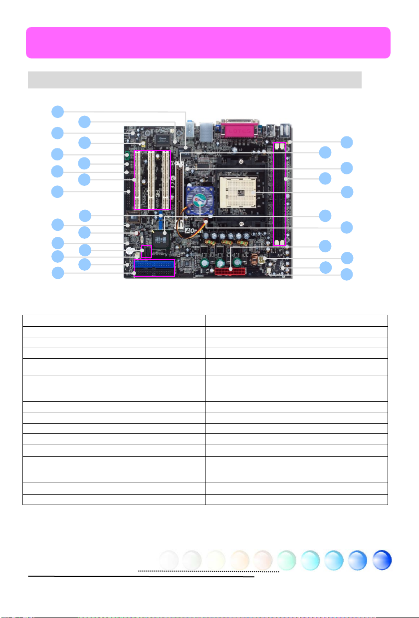
p
17 18 19
Chapter 2 Introduction to This Motherboard
Chapter 2 Introduction to This Motherboard
2.1 How does your motherboard look like?
12
1. JP28 PS2 KB/Mouse Wakeup Jumper 15. Front Audio Connector
2. AGP 8X Expansion Slot 16. AUX_IN Connector
3. AGP Protection LED 17. CD_IN Connector
4. 184-pin DIMMs x 2 18. IrDA Connector
5. 754-pin CPU socket supporting
AMD
6. SiS 760GX/ 964 chipsets
6. (s760GXm-SL & s760GXm-S)
6. SiS 760GX/ 964L chi
7. SYSFAN1 Connector 21. USB2.0 Connectors x 2
8. 20-pin ATX Power Connector 22. COM2 Connector
9. 4-pin 12V ATX Power Connector 23. JP14 CMOS Data Clear Jumper
10. STBY LED 24. S/PDIF Connector
11. CPUFAN Connector 25. Serial ATA Connectors x 2
12. Realtek Gigabit LAN Chip (s760GXm-SL)
12. Realtek 10/100Mbps LAN Chip
12. (s760GXm-S/ s760GXm)
13. Case Open Connector 27. Front Panel Connector
14. Onboard AC’97 CODEC 28. ATA133 Connectors x 2
14
16
20
22
24
26
28
TM
Athlon
13
15
21
23
25
27
TM
64 CPU
sets (s760GXm)
2
4
6
8
10
19. 32-bit PCI Expansion Slots x 3
20. FDD Connector
26. SYSFAN2 Connector
1
3
5
7
9
11
5
Page 6
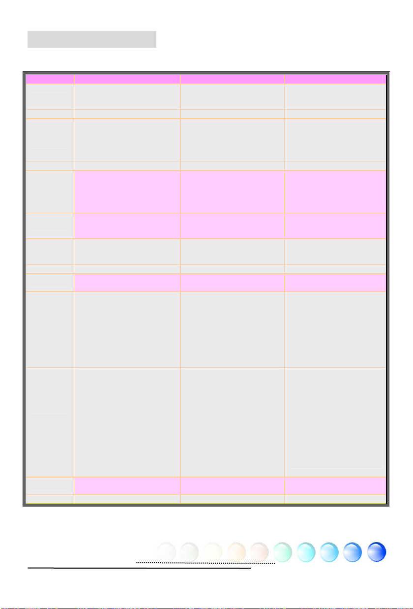
2.2 Specification
Here is the main function of your motherboard.
Models s760GXm-SL s760GXm-S s760GXm
CPU
Chipset SiS 760GX / SiS 964 SiS 760GX / SiS 964 SiS 760GX / SiS 964L
Main
Memory
Graphics 8X AGP slot 8X AGP slot 8X AGP slot
IDE
LAN
Sound
USB USB 2.0 x 8 USB 2.0 x 8 USB 2.0 x 8
Slots
Back Panel
I/O
On Board
Connector
BIOS
Board Size 244 mm x 220 mm 244 mm x 220 mm 244 mm x 220 mm
AMD Athlon 64 CPU
Socket 754
800MHz
DDR 266/333/400MHz
DDR DIMM x 2
DIMM T yp e :
64/128/256/512MB & 1GB
Max Memory : 2GB
Integrated ATA133 and
Serial ATA Controller (Raid
0, 1 supported)
Max Disk: 144,000,000GB
[by 48 bits LBA Spec.]
Realtek Gigabit LAN
Controller, support
10/100/1000Mbps
Realtek AC'97 CODEC
onboard, support 5.1
Channel
AGP x 1
PCI x 3
PS/2 Keyboard x 1
PS/2 Mouse x 1
USB Port x 4
LAN Port x 1,
COM Port x 1
VGA Port x 1
Printer Port x 1
Speaker_Out x 1
Line_In x 1, MIC_In x 1
FDD Connector x 1
ATA133 Connectors x 2
Serial ATA Connectors x 2
Front Panel x 1
Front Audio x 1
CPU FAN x 1,Sy stem FAN x
1,Chassis FAN x 1, Power
Temperature Connector x 1
Case Open Connector x 1 ,
IrDA Connector x 1
S/PDIF Connector x 1,
CD_IN x 1, AUX_IN x 1
USB connector x 2
Award PnP 4Mb Flash ROM
BIOS
AMD Athlon 64 CPU
Socket 754
800MHz
DDR 266/333/400MHz
DDR DIMM x 2
DIMM T yp e :
64/128/256/512MB & 1GB
Max Memory : 2GB
Integrated ATA133 and
Serial ATA Controller (Raid
0, 1 supported)
Max Disk: 144,000,000GB
[by 48 bits LBA Spec.]
Realtek 10/100Mbps LAN
Controller, support
10/100Mbps
Realtek AC'97 CODEC
onboard, support 5.1
Channel
AGP x 1
PCI x 3
PS/2 Keyboard x 1
PS/2 Mouse x 1
USB Port x 4
LAN Port x 1
COM Port x 1
VGA Port x 1
Printer Port x 1
Speaker_Out x 1
Line_In x 1, MIC_In x 1
FDD Connector x 1
ATA133 Connectors x 2
Serial ATA Connectors x 2
Front Panel x 1
Front Audio x 1
CPU FAN x 1,Syst em FAN x
1,Chassis FAN x 1, Power
T emperature Con nector x 1
Case Open Connector x 1 ,
IrDA Connector x 1
S/PDIF Connector x 1,
CD_IN x 1, AUX_IN x 1
USB connector x 2
Award PnP 4Mb Flash ROM
BIOS
AMD Athlon 64 CPU
Socket 754
800MHz
DDR 266/333/400MHz
DDR DIMM x 2
DIMM T yp e :
64/128/256/512MB & 1GB
Max Memory : 2GB
Integrated ATA133
Controller
Max Disk: 144,000,000GB
[by 48 bits LBA Spec.]
Realtek 10/100Mbps LAN
Controller, support
10/100Mbps
Realtek AC'97 CODEC
onboard, support 5.1
Channel
AGP x 1
PCI x 3
PS/2 Keyboard x 1
PS/2 Mouse x 1
USB Port x 4
LAN Port x 1
COM Port x 1
VGA Port x 1
Printer Port x 1
Speaker_Out x 1
Line_In x 1, MIC_In x 1
FDD Connector x 1
ATA133 Connectors x 2
Front Panel x 1
Front Audio x 1
CPU FAN x 1,Sy stem FAN x
1,Chassis FAN x 1, Power
T emperature Connector x 1
Case Open Connector x 1 ,
IrDA Connector x 1
S/PDIF Connector x 1,
CD_IN x 1, AUX_IN x 1
USB connector x 2
Award PnP 4Mb Flash ROM
BIOS
6
Page 7
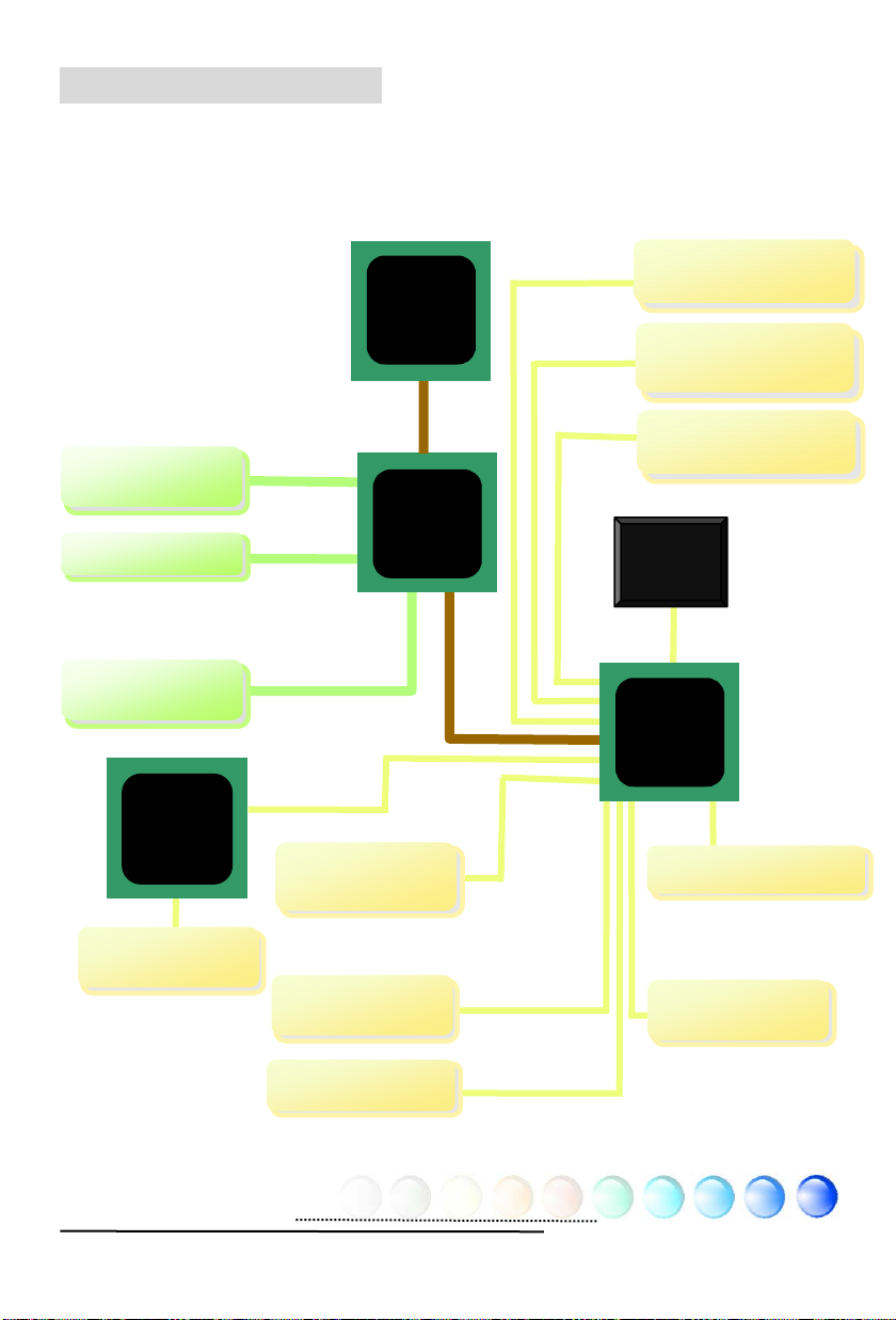
2.3 Block Diagram
/
p
(
VGA Onboard
AGP 8X Slot
DIMM Sockets x2
Realtek
Gigabit
LAN Chip
AMD Athlon 64
CPU
800MHz
System Bus
AGP bus
DDR400/333/266
RAM Up to 2 GB
10/100Mpbs
for s760GXm-S/s760GXm)
USB Ports x8
Socket 754
SiS 760GX
PCI Bus
150MB
32-bit PCI Slots x3
s
Serial ATA Ports x 2
Raid 0, 1 Supported)
ATA
66/100/133
IDE Drives x 4
RealTek
AC97
CODEC
SiS 964
(s760GXm-SL
/s760GXm-S)
SiS 964L
(s760GXm)
4Mbits FlashEEPROM
LAN connect
Com
onent
Floppy Disk
Drive
Parallel Port
Serial Ports x2
7
Page 8
Chapter 3 Hardware Installation
Chapter 3 Hardware
r
q
Installation
3.1 Quick Installation Procedure
2. Installing CPU
Fan & System Fan
3. Installing
Memory Module
4. Installing HD,
CD-ROM and
SATA Disk, etc
5. Connecting Front
Panel Cable
1. Installing CPU
6. Connecting ATX
Power Cable
12. Installing Drivers &
Utilities
11. Installing
Operating System
(such as, Windows
XP)
8. Installing Othe
Devices (USB, Front
Audio, etc)
7. Installing AGP & PCI
Cards
10. Loading
Default BIOS,
Setting CPU
uency
Fre
9. Connecting
Back Panel Ports
(Keyboard,
Mouse, etc)
8
Page 9

3.2 Installation You Have to Know
m
d
Installing CPU
This motherboard supports AMD® Athlon 64 Socket 754 CPU. Be careful of CPU
orientation when you plug it into CPU socket (with CPU Overheat Protection
function implemented, the system will be automatically power off when the
temperature of CPU reached 97 degree).
1. Pull up the CPU socket lever and up to 90-degree angle.
2. Locate Pin 1 in the socket and look for a golden arrow on the CPU upper
interface. Match Pin 1 and golden arrow. Then insert the CPU into the
socket.
3. Press down the CPU socket lever to finish CPU installation.
CPU socket lever
Socket Pin 1
Golden Arrow
9
Page 10

Installing CPU and System Fans
Plug the CPU fan cable to the 3-pin CPUFAN connector. If you have chassis fan,
you can also plug it in SYSFAN1 or SYSFAN2 connector.
SYSFAN2 Connector
GND
+12V
SENSOR
SYSFAN1 Connector
CPUFAN Connector
Note: Some CPU fans
do not have sensor pin so
that they cannot support fan
monitoring.
GND
+12V
SENSOR
GND
+12V
SENSOR
10
Page 11
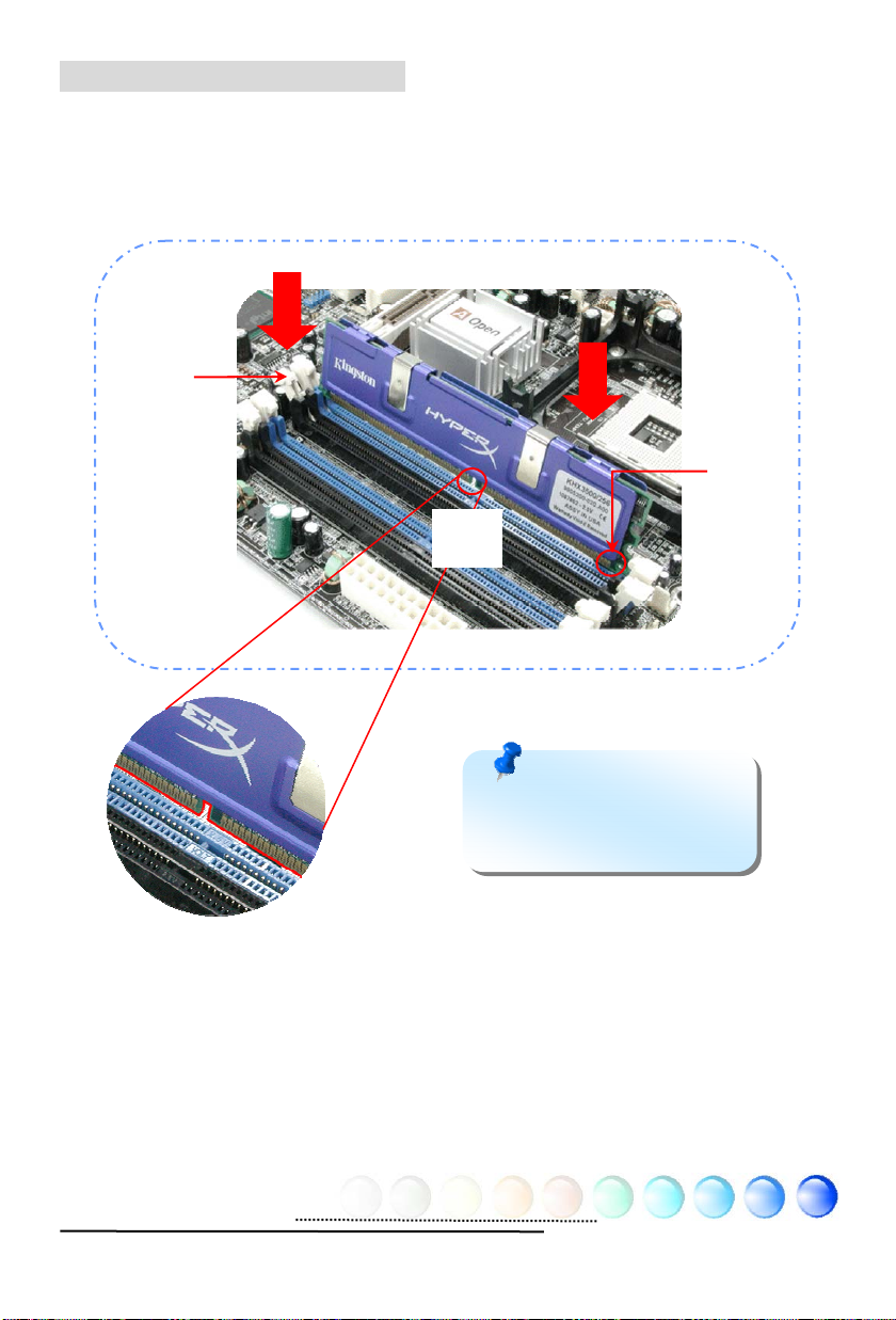
Installing Memory Modules
DIMM slots are designed in black which are very easy to recognize. Insert the
module straight down to the DIMM slot with both hands and press down firmly
until the DIMM module is securely in place.
Tab
Pin 1
Key
Note: The tabs of the
DIMM slot will clip to hold the
DIMM in place when the DIMM
touches the slot’s bottom.
11
Page 12
Connecting IDE and Floppy Cables
Connect the 34-pin floppy cable and 40-pin, 80-wire IDE cable to floppy
connector and IDE connector. Be careful of the pin1 orientation. Wrong
orientation may cause system damage.
Pin 1
FDD Connector
Primary
Master (1st)
Primary
Slave (2nd)
IDE 1 (Primary)
Pin 1
Secondary
Master (3rd)
AT A 66/100/133
IDE Connector
IDE 2 (Secondary)
Secondary
Slave (4th)
12
Page 13
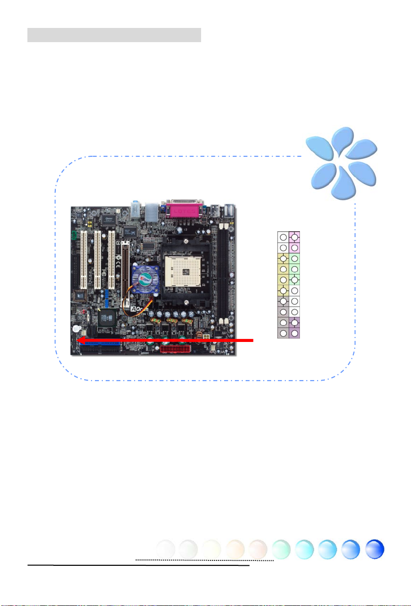
Connecting Front Panel Cable
Attach the power LED, speaker and reset switch connectors to the corresponding
pins. If you enable “Suspend Mode” item in BIOS Setup, the ACPI & Power LED
will keep flashing while the system is in suspend mode.
Locate the power switch cable from your ATX housing, which is a 2-pin female
connector from the housing front panel. Plug this connector to the soft-power
switch connector marked SPWR.
HDD LED
HDD LED
SPEAKER
Front Panel Connector
NC
NC
+5V
+5V
+5V
GND
NC
1
Power Switch
GND
Power LEDGND
Power LED+
NC
GND
GND
RESET
GND
13
Page 14
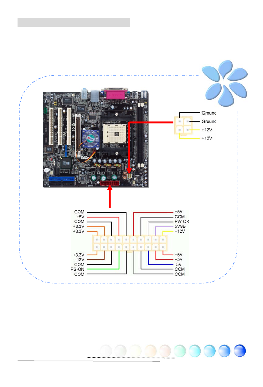
Connecting ATX Power Cables
This motherboard comes with a 20-pin and 4-pin ATX power connector as shown
below. Make sure you plug them in the right direction. We strongly recommend
you to insert the 4-pin connector before connecting the 20-pin connector.
14
Page 15

3.3 Other Installation for Your Reference
Setting CPU Voltage and Frequency
Setting CPU Core Voltage
This motherboard supports Voltage ID (VID) function to detect CPU voltage
automatically during power-on.
Setting CPU Frequency
This motherboard is of CPU jumper-less design; you can set CPU frequency by
1MHz stepping CPU Overclocking in the BIOS. CPU Core Frequency = CPU FSB
clock x CPU Ratio. However, all CPU now sold in market belong to "Fixed
Multiplier". That means users can not adjust the CPU Ratio but change CPU FSB
clock to achieve overclocking only.
BIOS Setup > Frequency / Voltage Control > CPU Speed Setup
(Users will do the overclocking at their own risks!!)
AMD CPU CPU Core Freq. CPU Clock L2 Cache Ratio
Athlon 64 2800+ 1800MHz 200MHz 512KB 9x
Athlon 64 3000+ 2000MHz 200MHz 512KB 10x
Athlon 64 3200+ 2000MHz 200MHz 1024KB 10x
Athlon 64 3200+ 2200MHz 200MHz 512KB 11x
Athlon 64 3400+ 2200MHz 200MHz 1024KB 11x
Athlon 64 3400+ 2400MHz 200MHz 512KB 12x
Athlon 64 3700+ 2400MHz 200MHz 1024KB 12x
Note: With CPU speed changing rapidly, there might be faster CPU on the
market by the time you received this installation guide. This table is kindly
for your references only.
Note: If your system hangs or fails to boot because of overclocking, simply use
<Home> key to restore the default setting or you can wait the AOpen “Watch Dog
ABS” reset the system in five seconds and system will auto-detect hardware again .
Warning: SiS 760GX chipset supports maximum 800MHz system clock and
66MHz AGP clock; higher clock setting may cause serious system damage.
CPU Ratio From 4x to 25x step 1x
CPU FSB (Adjustment
manually)
FSB = 200MHz-250MHz by 1 MHz Stepping CPU Overclocking
15
Page 16

Connecting Serial ATA
To connect a serial ATA disk, you have to have a 7-pin serial ATA cable. Connect
two ends of the serial AT A cable to the serial A T A header on the motherboard and
the disk. Like every other traditional disk, you also have to connect a power cable.
Please be noted that it is a jumper free implement; you don’t need to set jumpers
to define a master or slave disk. When serial AT A hard disks are installed on serial
AT A ports, the one connected on P ort0 (SA T A1) will be set as the first boot device
automatically. Please note that it doesn’t support Hot-Plug in function.
SATA2
Port1
SATA1
Port0
16
Page 17
Adjusting your Hard Disk Setting
Except its original 2 sets of parallel IDE, this motherboard supports the latest
serial AT A hard disk. If you are unable to find your newly installed serial A T A har d
disks on your operating system after having them installed, the problem may lie
in the BIOS setting. You can simply adjust BIOS settings to have them work
properly.
After installing your hard disks properly, you can directly go to BIOS setting
screen for adjustment. Simply pressing “Integrated Peripherals
OnChip PCI Device
Æ
SIS Serial ATA Controller” to either enable or disable
SATA interface.
Æ
SIS
17
Page 18

Connecting AGP 8X Expansion Slot
This motherboard provides an AGP 8X slot. The AGP 8X is a bus interface targeted
for high-performance 3D graphic. Traditionally AGP used both rising and falling
edge of the 66MHz clock for 4X AGP, and the data transfer rate could achieve
66MHz x 4bytes x 4 = 1056MB/s. Now AGP is moving to AGP 8X mode, which is
upgraded to 66MHz x 4bytes x 8 =2.1GB/s.
Warning: It is strongly recommended not adjust AGP/PCI
voltage/clock when you connect SATA device. It is becau se when
the voltage/clock for AGP/PCI is adjusted, the SATA clock cannot
remain at 100MHz, and the system will therefore be unstable.
18
Page 19

Connecting IrDA
The IrDA connector can be configured to support wireless infrared module, with
this module and application software such as Laplink or Windows Direct Cable
Connection, user can transfer files to or from laptops, notebooks, PDA devices
and printers. This connector supports both HPSIR (115.2Kbps, 2 meters) and
ASK-IR (56Kbps).
Install an infrared module onto the IrDA connector and enable the infrared
function from BIOS Setup, UART Mode, you can use this function. Please make
sure you connect correct orientation when plugging IrDA module.
Pin 1
19
1
NC
+5V
IR_TX
KEY
GND
IR_RX
IrDA Connector
Page 20

10/100/1000Mbps LAN Supported (1000Mbps for s760GXm-SL only)
On the strength of Gigabit LAN controller (for s760GXm-SL) on board, this
motherboard provides 10/100/1000Mbps Ethernet for office and home use (for
s760GXm-S / s760GXm, it is 10/100 Mbps). The Ethernet RJ45 connector is
located on the top of USB connectors. The right hand side LED indicates link mode;
it lights in yellow when linking to network. The left hand side LED indicates the
transfer mode and will light in green when data is transferring at 100Mbps (never
lights while at 10Mbps), but will light in orange when transferring in Gigabit’s
mode. T o enable or disable this function, you may simply adjust it through BIOS.
T o enable LAN wakeup function, you have to set the “Wake on PCI Card” enable in
the BIOS “Power Management Setup” section.
Speed LED (Left)
Green 100Mbps
Orange Gigabit mode
ACT LED (Right)
Yellow
20
Page 21
Connecting USB2.0
g
This motherboard provides eight USB 2.0 ports to connect USB devices such as
mouse, keyboard, modem, printer, etc. There are four ports on the back panel.
You can also use proper cables to connect Front USB connector to USB modules or
chassis front panel.
Pin 1
Pin 1
SBD6+
12
+5V
SBD6-
GND
KEY
9 10
USB Connector
+5V
SBD7-
SBD7+
GND
NC
21
Page 22

Connecting S/PDIF
S/PDIF (Sony/Philips Digital Interface) is a newest audio transfer file format,
which provides impressive audio quality through optical fiber and allows you to
enjoy digital audio instead of analog audio. Through a specific audio cable, you
can connect the S/PDIF connector to other end of the S/PDIF audio module, which
bears S/PDIF digital output. Normally there are two S/PDIF outputs as shown,
one for RCA connector, the most common one used for consumer audio products,
and the other for optical connector with better audio quality. Same as outputs,
you can also connect RCA or optical audio products to input connectors on the
module and have the voice or music come out from your computer . However, you
must have a S/PDIF supported speaker/amplifier/decoder with S/PDIF digital
input/output to connect to the S/PDIF digital input/output to make the most out
of this function.
Pin 1
SPDIF OUT
SPDIF IN
5
GND
+5V
KEY
S/PDIF Connector
(RCA)
S/PDIF OUT
1
S/PDIF IN
S/PDIF OUT
S/PDIF IN
(Optical)
S/PDIF Module
S/PDIF
Cable
22
Page 23

Super 5.1 Channel Audio Effect
This motherboard comes with an AC’97 CODEC, which supports high quality of
5.1 Channel audio effects, bringing you a brand new audio experience. On the
strength of the innovative design of AC’97 CODEC, you're able to use standard
line-jacks for surround audio output without connecting any external module. To
apply this function, you have to install the audio driver in the Bonus Pack CD as
well as an audio application supporting 5.1 Channel. Picture below represents the
standard location of all speakers in 5.1 Channel sound tracks. Please connect the
plug of your front speakers to the green “Speaker out” port, rear speakers’ plug
to the blue “Line in” port and both of the center and subwoofer speakers to the red
“MIC in” port.
23
Page 24
Connecting Front Audio
r
Y
_
_
If the housing is designed with an audio port on the front panel, you’ll be able to
connect onboard audio to front panel through this connector. By the way, please
remove the jumper cap from the Front Audio Connector before you connect the
cable. Do not remove this yellow jumper cap if your housing doesn’t have an
audio port on the front panel.
Pin1
AUD
AUD MIC BIAS
FPOUT_R
AUD
AUD_FPOUT_L
1
MIC
NC
AUD_GND
AUD_VCC
AUD_RET_R
KE
AUD_RET_L
Front Audio Connecto
24
Page 25

Connecting CD_IN
This connector is designed to connect CD Audio cable from CDROM or DVD drive
to onboard sound.
R
GND
GND
L
CD-IN Connector
25
Page 26
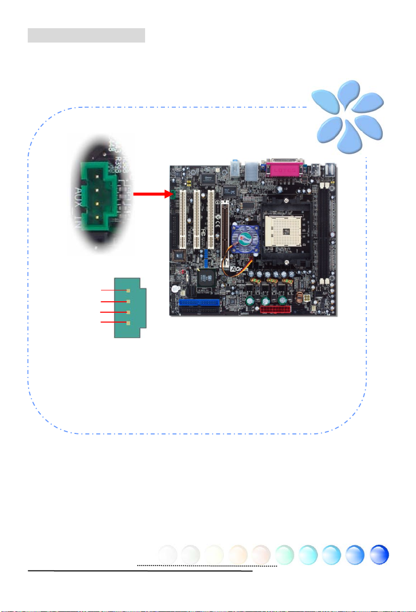
Connecting AUX_IN
This connector is used to connect MPEG Audio cable from MPEG card to onboard
sound.
R
GND
GND
L
AUX-IN Connector
26
Page 27

Connecting Case Open
r
The “CASE OPEN” header provides chassis intrusion-monitoring function. To
make this function work, you have to enable it in the system BIOS, connect this
header to a sensor somewhere on the chassis. So, whenever the sensor is
triggered by lights or by the opening of the chassis, the system will beep to inform
you. Please be informed that this useful function only applies to advanced chassis;
you may purchase an extra sensor, attach it on your chassis and make a good use
of this function.
Pin 1
Chassis Intrusion Connecto
1
Sensor
GND
27
Page 28

Connecting COM2
R
This motherboard provides two serial ports. One of them is on back panel
connector, and the other is on the left of board below FDD connector . With proper
cable, you can connect it to the back panel of chassis.
Pin 1
CTS#
DSR#
DTR#
Sin
2
COM Connector
R1#
TS#
GND
SOUT
DCD#
1
28
Page 29

Colored Coded Back Panel
The onboard I/O devices have PS/2 Keyboard, PS/2 Mouse, RJ-45 LAN Connector ,
COM1, VGA port, Printer, USB, AC’97 sound and game ports. The view angle of
drawing shown here is from the back panel of the housing.
PS/2 Mouse
Connector
PS/2 Keyboard
Connector
USB 2.0
Ports
COM 1 Port
SPP/EPP/ECP
Parallel Port
VGA Port
PS/2 Keyboard: For standard keyboard, which use a PS/2 plug.
PS/2 Mouse: For PC-Mouse, which use a PS/2 plug.
USB Port: Available for connecting USB devices.
Parallel Port: To connect with SPP/ECP/EPP printer.
RJ45
LAN Jack
USB 2.0
Ports
Line-In
Speaker Out
MIC-In
COM1 Port:
To connect with pointing devices, modem or others serial
devices.
RJ-45 LAN Port:
To connect Ethernet for home or office use.
VGA Connector: To connect with PC monitor.
Speaker Out: To External Speaker, Earphone or Amplifier.
Line-In: Comes from the signal sources, such as CD/Tape player.
MIC-In: For Microphone
29
Page 30
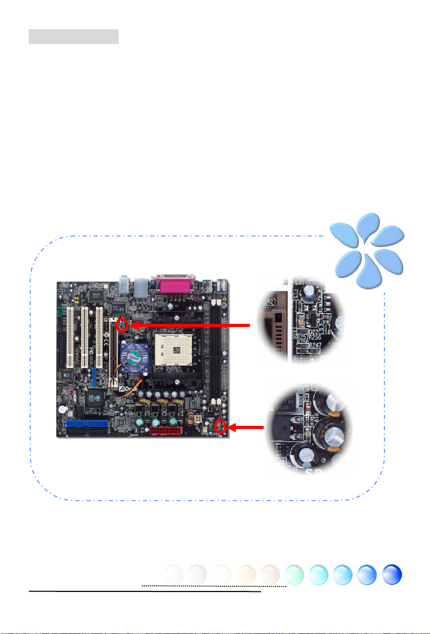
LED Indication
LED indication including Standby LED and AGP LED are AOpen’s considerate
designs that aim at providing you friendly system information.
STBY LED will light up when power is provided to the motherboard, giving you a
convenient indication check the system power status in circumstances such as
power on/off, stand-by mode and RAM power status during Suspend to RAM
mode.
AGP LED aims to protect your motherboard from being damaged by over voltage
of AGP card. When AGP Protection T echnolog y is imp lemente d, this mot herboa rd
will automatically detect the voltage of AGP card and prevent your chipsets from
being burnt out. Please note that if you install an AGP card with 3.3V , which is not
supported by SiS 760GX chipset, the AGP LED on the motherboard will light up to
warn you the possible damage of the exceeding voltage.
AGP LED
STBY LED
30
Page 31

3.4 Jumper Settings
C
JP28 Keyboard / Mouse
Wakeup Jumper
This motherboard provides PS2 keyboard / mouse
wake-up function.
JP28 Keyboard / Mouse Wakeup Jumper
1
Disable
(Default)
JP14 Clear CMOS Jumper
1
Normal
(Default)
Clear CMOS
1
Enable
1
JP14 Clear CMOS Data
You can clear CMOS to restore system default setting. To
clear the CMOS, follow the procedure below.
1. Turn off the system and unplug the AC power.
2. Remove ATX power cable from connector PWR2.
3. Locate JP14 and short pins 2-3 for a few seconds.
4. Return JP14 to its normal settin g by shorting pin 1 & pin 2.
5. Connect ATX power cable back to connector PWR2.
31
Page 32
Chapter 4 Special Features and Utilities
Chapter 4 Special Features and Utilities
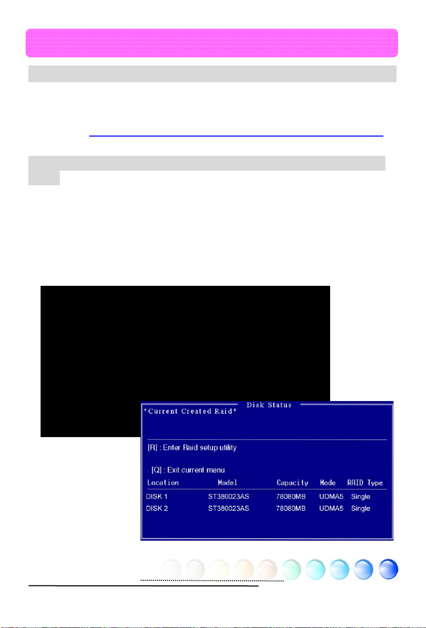
RAID (Redundant Array of Independent Disks)
With the latest chipsets implemented, SiS 964 provides RAID 0 and RAID 1
function for the Serial ATA hard disks. You may use RAID BIOS Setting Utility
provided by SiS to setup your disk array . For more RAID introduction, please visit
our website: http://english.aopen.com.tw/tech/techinside/RAID.htm
RAID BIOS Setting Utility (for s760GXm-SL / s760GXm-S only)
In order to make sure your system can recognize and operate Serial ATA RAID
device smoothly, we have to enter RAID BIOS Setting Utility to do some
configuration. After finishing the BIOS setup and reboot, you will see [Press
<CRTL><S> to run BIOS Setting Utility] about half way through the boot up.
When you enter you will be presented with a screen as shown below. Y ou can use
this utility to create or delete your disk arrays.
Silicon Integrated Systems Corp. RAID BIOS Setting Utility v1.xx
(c) 2003-2005 Silicon Integrated Systems Corp.All Right Reserved.
Press <CTRL><S> to run BIOS Setting Utliity
Scan Device. Please Wait………….
Primary Master : xxxxxxxx xxxxxxMB UDMA 5
Primary Slave : <Device Not Found>
Secondary Master : <SATA Device Not Found>
Secondary Slave : xxxxxxxx xxxxxMB UDMA 5
[RAID Information]
32
Page 33

Other Useful Features
With excellent design ability of R&D team, AOpen boasts for its various powerful
and handy features that come with our product like follows. You are welcomed
to visit our technical website to learn more about those features.
http://english.aopen.com.tw/tech/techinside
33
Page 34

Chapter 5 Setting BIOS
Chapter 5 Setting BIOS
Introduction
System parameters can be modified by going into BIOS Setup menu; this menu
allows you to configure the system parameters and save the configuration into
the 128 bytes CMOS area (normally in the RTC chip or in the main chipset).
The Phoenix-Award BIOS™ that installed in the Flash ROM of the motherboard is
a custom version of an industry standard BIOS. The BIOS provides critical
low-level support for standard devices such as hard disk drives, serial and parallel
ports.
AOpen’s R&D engineering team had optimized most BIOS settings of this
motherboard. However, some default settings of BIOS cannot fine-tune those
sections that controlled by chipset. Therefore, this chapter is intended to guide
you and help you to configure some other settings.
T o enter BIOS setup menu, press <Del> when POST (P ower-On Self Test) screen
is shown on your monitor.
Note: Because BIOS code is the most
often changed part on motherboard, the BIOS
information contained in this manual may be
different from the BIOS version that comes with
your motherboard.
34
Page 35

How To Use Phoenix-Award™ BIOS Setup Program
Generally, you can use arrow keys to highlight items that you want to choose,
press <Enter> key to select, and use <Page Up> and <Page Down> keys to
change setting values. You can press <Esc> key to quit Phoenix-Award™ BIOS
setup program. The following table provides details about how to use keyboard in
the Phoenix-AwardBIOS setup program.
Key Description
Page Up or + Change setting to next value or increase the value.
Page Down or - Change setting to previous value or decrease value.
Enter Select the item.
Esc In main menu: Quit without saving any changes.
In sub menu: Exit current menu to main menu.
Up Arrow Highlight previous item.
Down Arrow Highlight next item.
Left Arrow Move the light bar to left side of menu.
Right Arrow Move the light bar to right side of menu.
F6 Load Setup Default setting value from CMOS.
F7 Load turbo setting value from CMOS.
F10 Save changed settings and exit setup program .
How To Enter BIOS Setup
After finishing the jumper settings and connecting cables, you can power on and
enter the BIOS Setup. Press <Del> during POST (Power-On Self T est) and choose
"Load Setup Defaults" for recommended optimal performance.
Del
Warning: Please avoid of using “Load
Turbo Defaults”, unless you are certain your
system components (CPU, SDRAM, HDD, etc.)
are good enough for turbo setting.
35
Page 36
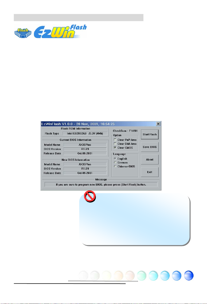
BIOS Upgrade under Windows environment
With outstanding R&D ability of AOpen, we now bring you a whole new BIOS Flash
wizard ---- EzWinFlash. With an eye to convenience for users, EzWinFlash
combines the BIOS binary code and flash module together, so the only thing you
have to do is just c lic kin g o n t he u til it y y o u d ownlo a de d from web a nd let it he lp
you complete the flash process automatically. EzWinFlash detects your
motherboard and checks the BIOS version cleverly to prevent your system from
any possible failure. Moreover, EzWinFlash has been taken into consideration to
go with any windows platform you might be using, no matter if you’re using
Windows 98, 98SE/ME, NT4.0/2000, or Windows XP.
In the meanwhile, in order to provide a much more user-friendly operating
environment, AOpen EzWinFlash is natively designed to have multi-language
function to provide easier way for user in changing BIOS setting.
Caution: You are taking a risk of BIOS flash
failure when you update your system. If your
motherboard is working stable, and there are no
major bugs to be fixed by a latter BIOS revision,
we recommend that you DO NOT upgrade your
BIOS. If you intent on upgrade PLEASE MAKE
SURE you get the right BIOS revision for your
motherboard model so as to avoid any possible
failure.
Note: The model name on this BIOS picture is for reference only. It may
not be the same model with your motherboard.
36
Page 37

You may accomplish BIOS upgrade procedure with EzWinFlash according to
following steps, and it’s STRONGLY RECOMMENDED to close all applications
before you start the upgrades.
Download the latest ve rsion of BIOS packag e zip file from AOpen official web site.
(Ex: http://english.aopen.com.tw/)
Unzip the downloaded BIOS package (ex: S760GXMSL102.ZIP) with WinZip
(http://www.winzip.com) in Windows environment.
Save the unzipped files into a folder, for example, S760GXMSL102.EXE &
S760GXMSL102.BIN.
Double click S760GXMSL102.EXE; EzWinFlash will detect the model name and
BIOS version of your motherboard. If you collect wrong BIOS, you will not be
allowed to proceed with the flash steps.
You may select a preferred language in main menu, then click [Start Flash] to
begin the BIOS upgrade procedure.
EzWinFlash will complete all the process automatically, and a dialogue box will
pop up to ask you to restart Windows. Click [YES] to reboot Windows.
Press <Del> at POST to enter BIOS setup screen; choose "Load Setup Defaults",
then “Save & Exit Setup”. Done!
It is strongly recommended NOT to turn off the power or run any applications
during FLASH PROCESS.
Warning: The new BIOS upgrade will
permanently replace your original BIOS setti ng
when flashing. You may need to reconfigure the
BIOS setting before your system goes back to
work as normal.
37
Page 38

Vivid BIOS technology
Have you been fed up with the conservative and immutable POST screen? Let’s
rule out the tradition idea that POST screen are stiff and frigid, and let AOpen
show you the newly developed VividBIOS to ex perience the lively vivid colorful
POST screen!
Unlike earlier graphic POST screen which could occupy the whole screen and
mask text information during POST, AOpen VividBIOS deals with graphics and
texts separately , and makes them running simultaneously during POST. With this
innovative design, VividBIOS now brings you a beautiful and sleek 256 colors
screen without missing any important information shown on POST screen.
In addition, the limited space of BIOS ROM is another big issue. When all of the
traditional BIOS can only show space-consuming and uncompressed Bitmap,
AOpen has considerately tuned the BIOS to next generation, to recognize the
smaller-sized GIF format and even dynamic-showing GIF animation.
Vivid BIOS shares the same fundamental technology with Open JukeBox CD
Player , you may use the same EzSkin utility to change your VividBIOS screen or to
download your fav orite Open JukeBo x skin. If you se e this little logo s hown beside
your model name on the motherboard download page,
http://english.aopen.com.tw/tech/ezskin/vivid.htm
that your motherboard supports this innovative feature!
, it is assured
38
Page 39

Chapter 6 Installing Drivers
Chapter 6 Installing Drivers
You may think that installing drivers and utilities would be a repeated task of going
through those installation wizards and steps-by-steps. Now, you will be surprised
with how “Ez” EzInstall could do. Without wizards or steps, all you have to do is to
do one click and then it’s done. Click and done. Yes. EzInstall makes installation
easy and even foolproof!
After putting in the CD, you will be prompted with AOpen welcome page and our
branches information.
First, click on the install driver ICON at left side for necessary drivers.
Second, click on the install utility ICON at left side for preferred utilities.
Practically, it’s done. But you may also browse CD contents, Readme to get more
information or just exit the CD installation.
Install
driver
Install
utility
Browse CD
Contents
Readme
Click to install
online manual
AOpen
branches
information
Exit CD
39
Page 40

6.1 Installing Drivers
As you may see from the Installing driver page, EzInstall had picked up necessary
for your motherboard. All you have to do is just click on the “GO”, and n o mor e
steps afterward, of all listed drivers, grey checks indicate necessary drivers; you
cannot click them off. R ed checks can be disabled if you don’t want to install them
now.
Press the icon will prompt the
“Install Driver” page. You
may also press “Back” to
return to the Main page.
Once clicking “GO”, EzInstall will run the installing procedure
automatically, and prompt a reboot dialog (Some drivers or
utilities may skip the reboot part).
40
Page 41

6.2 Installing Utilities
Installing Utilities is virtually the same as installing drivers. AOpen provides you
many friendly and powerful utilities to manage your system. Y ou may find lots of
fabulous utilities listed there, and all you have to do is to click on the “GO”, then
it will install the utilities to your system right away without complicated steps.
Press the icon will
prompt the “Install
Utilities” page for your
selection. You may also
press “Back” to get back
to the Main page.
41
Page 42
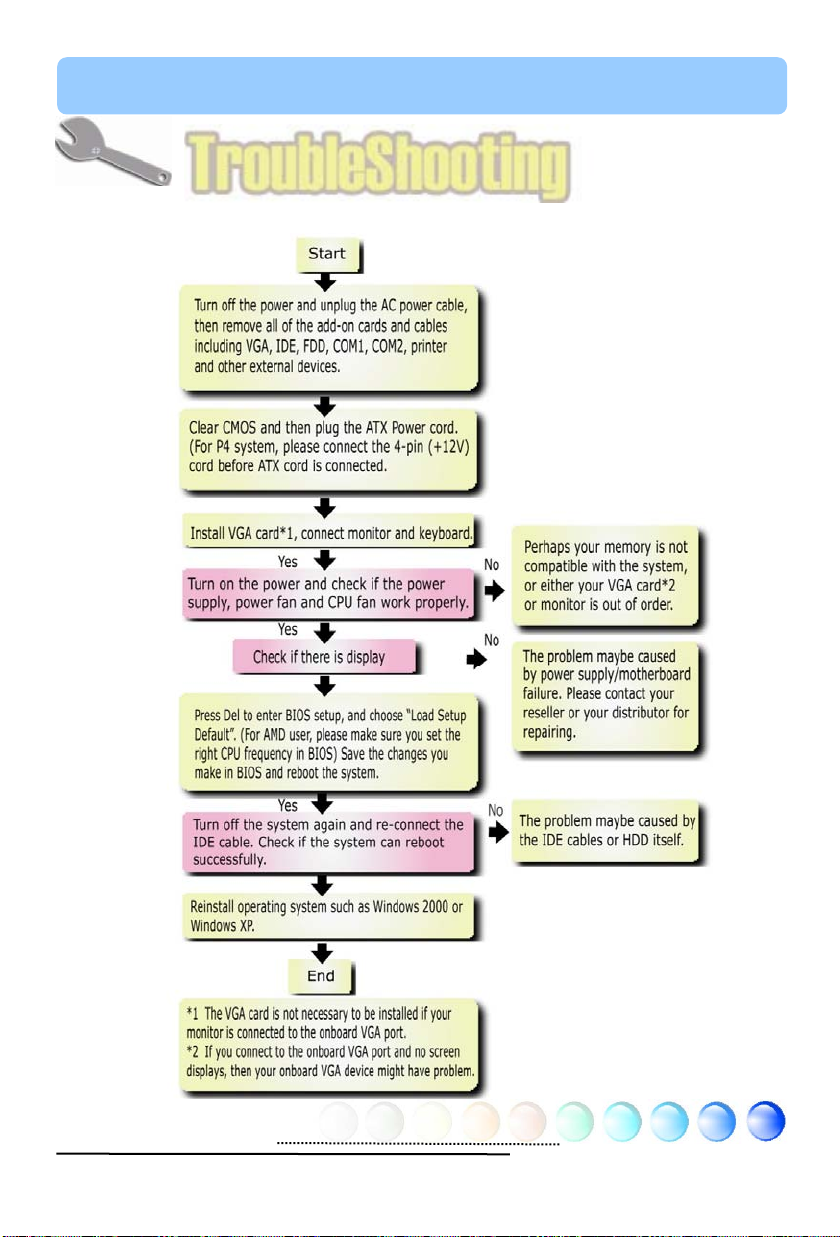
Chapter 7 Troubleshooting
g
Chapter 7 Troubleshootin
42
Page 43

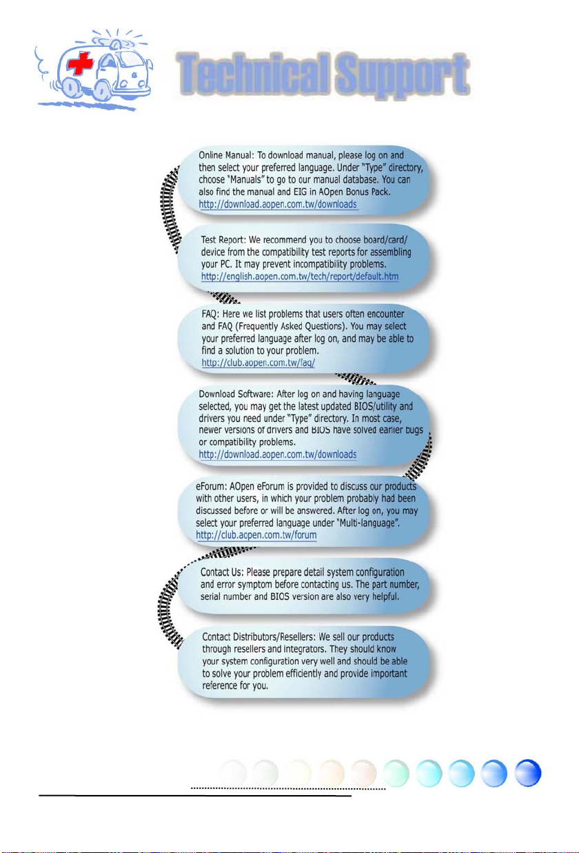
Chapter 8 Technical Support
Chapter 8 Technical Support
Dear Customer,
Thanks for choosing AOpen products. We invite you to register at
http://www.aopen.com
to become a Gold Member of Club AOpen so as to
ensure quality service in the future. In order to maintain the best service to every
customer of us, we recommend you to follow the procedures below and seek help
from our branches according to the region you buy the product. With your help,
we can then continue to provide efficient and the best quality service to every
customer.
Thanks very much for your understanding!
AOpen Technical Supporting Team
Europe
AOpen Computer b.v.
Tel: 31-73-645-9516
Email: Support@AOpen.NL
China
艾爾鵬國際貿易(上海)有限公司
Tel: 86-21-6225-8622
Fax: 86-21-6225-7926
Germany
AOpen Computer GmbH.
Tel: 49-2131-1243-710
Fax: 49-2131-1243-999
Europe Email: Support@AOpen.NL
Pacific Rim: http://www.aopen.com.tw/tech/default.htm
China: http://www.aopen.com.cn/tech/default.htm
Germany: http://www.aopencom.de/tech/default.htm
America: http://usa.aopen.com/tech/default.htm
Japan: http://aopen.jp/tech/index.html
Pacific Rim
AOpen Inc.
Tel: 886-2-3789-5888
Fax: 886-2-3789-5899
43
Japan
AOpen Japan Inc.
Tel: 81-048-290-1800
Fax: 81-048-290-1820
America
AOpen America Inc.
Tel: 1-510-489-8928
Fax: 1-510-489-1998
Page 44

Model Name and BIOS Version
Model name and BIOS version can be found on upper left corner of first boot
screen (POST screen). For example:
Phoenix AwardBIOS v6.00PG, An Energy Star Ally
Copyright (C) 2004, Phoenix Technologies, LTD.
s760GXm-SL R1.02 July. 01. 2004 AOpen Inc.
s760GXm-SL is model name of motherboard; R1.02 is BIOS version
Register Your Motherboard
Thanks for choosing AOpen product, please register this motherboard at
http://club.aopen.com.tw/productreg/
and to ensure high service quality and priority from AOpen. You will also have a
chance to play slot machine game to win prize from AOpen. Please prepare the
following information before you start: Model Name, Part Number (P/N), Serial
Number (S/N) and Purchase Date. The Part Number and Serial number are
printed on bar code label. You can find this bar code label on the outside packing
or on component side of PCB. For example:
to become a Gold member of Club AOpen,
P/N: 91.88110.201 is part number, S/N: 91949378KN73 is serial number.
Phoenix-Award BIOS ERROR Message
Beep Sound Message
1 short(Beep) System booting is normally.
1 long - 1 short(Beep) DRAM ERROR
1 long - 2 short(Beep) Display card or monitor connected error
1 long - 3 short(Beep) Keyboard Error
Long(Beep) continuous DRAM hasn't inset correctly.
Part No. Serial No.
44
Page 45
Technical Support
45
 Loading...